FACULTY OF ELECTRICAL ENGINEERING UNIVERSITI TEKNIKAL MALAYSIA MELAKA
FINAL YEAR PROJECT REPORT
BEKU 4792
Design and Development of Turning Motion Trajectory for Limb Assisting Device
Low Wai Tuck
Bachelor of Mechatronics Engineering
I hereby declare that I have read through this report entitle “Design and Development of Turning Motion Trajectory for Lower Limb Assistive Device” and found that it has comply the partial fulfillment for awarding the degree of Bachelor of Mechatronic Engineering.
Signature : _____________________
Supervisor name : _____________________
DESIGN AND DEVELOPMENT OF TURNING MOTION TRAJECTORY FOR LIMB ASSISTIVE DEVICE
LOW WAI TUCK
A report is submitted in partial fulfillment of the requirements for the degree of Bachelor of Mechatronic Engineering
Faculty of Electrical Engineering
UNIVERSITY TEKNIKAL MALAYSIA MELAKA
iii
I declare that this report entitle “Design and Development of Turning Motion Trajectory for
Limb Assistive Device” is the result of my own research except as cited in the references. The report has not been accepted for any degree and is not concurrently submitted in candidature of any other degree.
Signature: ………
Name: ………..
iv
ACKNOWLEDGEMENT
I would like to use this opportunity to thank everyone that helping and advising me during the research of turning motion trajectory generation for limb assistive device. By go through study, I am able to apply all my knowledge and ability in completing my final year project 1(FYP1) report. by this may, I can expand my knowledge and solve the engineering problem systematically and effectively for the future. Firstly, I would like to thank my FYP supervisor Dr. Fahmi bin Miskon for continuous give supporting idea and guiding me during completing my FYP2. Many useful skills and knowledge has been learned from him throughout the FYP1. Besides, I am also very thankful to my panel 1 and panel 2, Cik Nursabillilah binti Mohd. and Dr. Fariz bin Ali@ Ibrahim. They have provided me much useful information to improve my FYP2 report. Not only that , Cik Nur Maisarah bt Mohd also provide many useful guideline in writing report.
v
ABSTRACT
Nowadays, the number of disorders such as stroke, spinal cord injury and traumatic brain injury is increasing drastically in the society. For every year, there are about 40 million people around the world suffer for mobility disorder and cannot perform their daily life activity. By improved architecture of lower limb assistive device (LAD) in hip for turning motion, patients can have more perfect motion in walking. However, the angle and torque for turning trajectory still have not been discover fully and need to be test. The accuracy and stability for the lower limb devices is importance in order to avoid the excessive turning that might hurt the user. The design of exoskeleton robot is follows the turning trajectory of a normal person. The
vi
ABSTRAK
vii
TABLE OF CONTENTS
CHAPTER TITLE PAGE
ACKNOWLEDGEMENT iv
ABSTRACT v
TABLE OF CONTENTS vii
LIST OF TABLES x
LIST OF FIGURES xii
1 INTRODUCTION 1
1.1 Motivation 1
1.2 Problem Statement 3
1.3 Project Objectives 4
1.4 Scope of the Project 4
1.5 Outline of the Dissertation 4
2 LITERATURE REVIEW 6
2.1 Theory of Turning Trajectory 6
2.1.1 System block diagram 6
2.1.2Human Gait 8
2.1.3 Anatomy of turning trajectory 10
2.1.4 Cubic Polynomial 12
2.1.5 PD controller 14
2.2 Turning Trajectory Problems 15
2.2.1 The desire angle for a turning motion 15
viii
2.3 Position analysis 16
2.3.1 Comparison of the medial and lateral rotational angle 17
2.4 Performance indices 20
2.4.1 Accuracy 20
2.4.2 Stability 20
2.4.3 Torque 20
2.5 Comparison among available solution- trade off 21
2.5.1 The historical exoskeleton 21
2.5.2 Present exoskeleton with hip turning motion trajectory 22
2.6 Summary of literature review 26
3 RESEARCH METHODOLOGY 27
3.1 Turning motion trajectory 27
3.1.1 Applying theory in calculation 29
3.2 Validation of the proposed turning trajectory 30
3.2.1 Objective of experiment 31
3.2.2 Flow chart of turning trajectory generation 32
3.3 Experiment set up and procedu 33
3.3.1 Design of the experiment 35
3.3.2 Experiment conduct 39
3.3.3 Safety Precaution 41
3.3.4 Method of analysis 41
3.4 Development of prototype for validation of idea 42
3.4.1 Selection of actuator 42
3.4.2 Hardware of the experiment 45
3.4.3 Prototype assembly 47
4 RESULT AND DISCUSSION 51
4.1 Experimental result 51
ix
4.1.3 Phase of turning 65
5 DISCUSSION 69
6 CONCLUSION AND FUTURE WORK 70
7 REFERENCE 71
x
LIST OF FIGURES
TABLES TITLE PAGE
Figure 1 Chart for disable person 1
Figure 2 Simple block diagram for the system 6
Figure 3 Detail flow chart for the system 7
Figure 4 Cartesian coordinate system 8
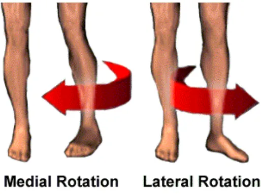
Figure 5 Medial and lateral rotational 9
Figure 6 Human Turning pattern 10
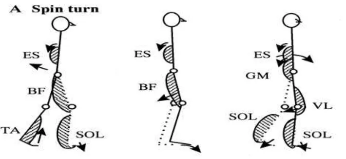
Figure 7 Spin turn pattern 10
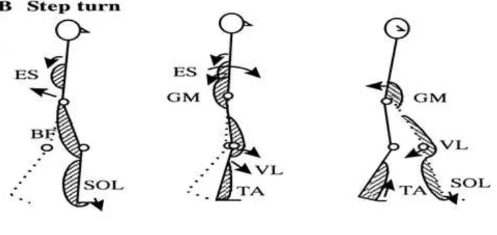
Figure 8 Step turn pattern 11
Figure 9 Graph of spin turn and step turn 12
Figure 10 Graph of cubic polynomial 13
Figure 11 Turning angle for lower limb 15
Figure 12
The rotational angle for medial and lateral rotational
16
Figure 13 Prone hip rotation 17
Figure 14 Laying position rotational 18
Figure 15 Sitting position rotational 19
Figure 16 The historical exoskeleton unit 21
Figure 17 Turning motion while walking 27
Figure 18 Method 1 of turning trajectory 28
Figure 19 Method 2 of turning trajectory 28
Figure 20 Flow chart of turning trajectory experiment 32
Figure 21 Component of the experiment 33
Figure 22 Experiment set up for experiment 34
xi
Figure 24 Accuracy of tracking for prototype 37
Figure 25 Water level ruler 39
Figure 26 Experiment set up for accuracy test 40
Figure 27 Prototype measurement 44
Figure 28 Arduino Uno Board 45
Figure 29 specification of the DC motor 46
Figure 30 The rotational angle for 45 degree 52
Figure 31 Percentage of error for DC motor 53
Figure 32 Tracking of accuracy graph (dc motor) 55
Figure 33 Turning trajectory for method 1 63
xii
LIST OF TABLES
TABLES TITLE PAGE
Table 1 Limit angle of rotational[11] 17
Table 2 Comparison of the design in turning motion 22 Table 3 Available solution tradeoff for turning motion 23
Table 4 Type of motor 43
Table 5 Specification of prototype 44
Table 6 Parts for the prototype 49
Table 7 DC motor accuracy 53
Table 8 RMSE and mean error for DC motor 54
Table 9 Experimental result in turning accuracy for prototype (method 1)
58 Table 10 Experimental result in turning accuracy for
prototype (method 2)
60 Table 11 Summary result for method 1 and method 2 62
Table 12 Comparison of the phase of turning 65
1
CHAPTER 1
INTRODUCTION
1.1 Motivation
Nowadays, the number of neurological disorders such as stroke, spinal cord injury and traumatic brain injury is increasing drastically in the society. Every year, there are estimated about 40 million people all around the world suffer from the problem. From the research, most of the patients are in the age group of 20 to 25[1]. Most of the patient affected by permanent movement disorder, such as hemiplegia, paraplegia or tremor.[2, 3]
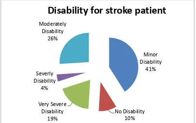
Figure 1: Chart for disable person
Minor Disability 41% No Disability 10% Very Severe Disability 19% Severly Disability 4% Moderately Disability 26%
2 The victim of the disease will cause mobility disorder and limit their movement. Most of them could not able to walk normally. Although the facilities and technology in rehabilitation and neuron rehabilitation is getting improved, the presence of mechatronic systems design is still in small amount. For the early 60’s, most of the researches are done by created powered hip exoskeleton devices to increase human strength[4, 5].
In summary, the thesis presents an improved architecture in hip exoskeleton unit. The theses mainly focus in the motion of turning trajectory on the hip. The turning trajectory is the motion of medial and lateral rotational on the hip. This enable the patient have more perfect movement in turning motion while walking.
3 1.2 Problem Statement
Development of a wearable lower limb exoskeleton robot must obey the physical human robot interaction fields (PHRI). The fields that focus are power, size, torque and safety. Suitable actuators that obey the movement of lower limb are electric motor. For safety, the size of the motor has to be compact and small which fulfill with the design of the wearable lower limb assistive devices. However, it has to be producing enough torque for the turning motion trajectory.
Stroke patient have limited degree of rotational for the lower limb part. The lower limb assistive device in the hip helps the patient in the turning motion. A suitable motor is needed to give enough torque for turning motion. The accuracy of the turning angle is important as well in turning motion trajectory. However, the suitable trajectory torque and angle for the turning motion are still not known. Especially, the particularly design for one leg assistive device for half body impaired person is still does not assist.
Besides, the design needs a high accuracy mechanism in term of rotational as the patient need to use the devices repeatedly. It is also avoid the excessive turning that might hurt the patient. Therefore, the maximum turning angle for the lateral and medial rotational has to be finding out. A suitable actuator is needed as it is design for the patients that are under rehabilitations.
4 1.3 Project Objectives
I. To design an exoskeleton robot that follows the turning trajectory of a normal person. II. To analyze the phase of turning trajectory according to the cubic polynomial.
III. To analyze the performance of the hip turning motion in term of accuracy and repeatability and the phase of turning.
1.4 Scope of the Project
I. The design is limit for two degree of freedom for the purpose of turning motion. II. The motion of turning trajectory is only focus on medial and lateral rotation III. The motion of the motor is control by Arduino Controller.
IV. The use of the dc motor only can attach to the prototype but not human.
V. For hardware part, the turning motion trajectory is tested by using a DC motor and feedback by encoder.
VI. The design of the turning trajectory for turning motion only for one side of leg.
VII. The prototype is not attach to a real person as the design is smaller due to the torque supply and safety for the user.
1.5 Outline of the Dissertation
The thesis includes several chapters and the road map of this thesis process as follows:
Chapter 1: Introduction
Include project motivation and the problem that happen in design the turning motion trajectory for lower limb assistive device. The project objective and the scope are listed in the chapter.
Chapter2: Literature review
5 human gait and cubic polynomial. Performances indices and comparison among the solution trade of is also being explained in the chapter.
Chapter3: Research Methodology
In the chapter, the design of procedure is discussed. The analysis is also done to test the performance of the device in term of accuracy, repeatability and stability.
Chapter4: Result
The accuracy for motor and prototype has been finding out and analyze. The error is calculated and being analyze. The phase of turning for 2 methods is plotted in term of the turning trajectory.
Chapter5: Discussion
The chapter is discussing the result for the experiment. The deviation of the turning angle is discussed. All the error and phase of turning is discuss.
Chapter 6: Conclusion and Recommendation
6
CHAPTER 2
2 LITERATURE REVIEW
2.1 Theory of Turning Trajectory
System block diagram 2.1.1
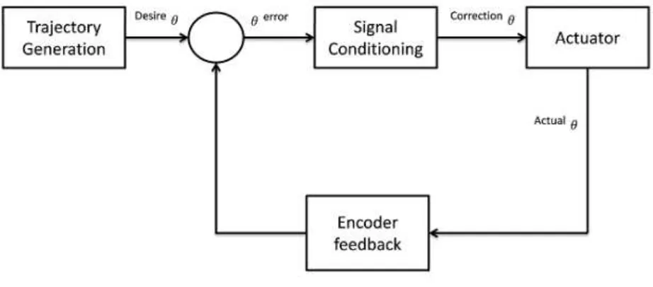
For the study of turning motion trajectory of lower limb assisting device, a simple block diagram is draw based on the requirement needed. First, a desire input (error) is act as a source and send to the controller which is signal conditioning. Then, the output will send to the actuator. The position will definitely deviate from the desired position. In order to make correction to the deviate, an encoder feedback is used to send a feedback signal to the signal conditioning. Then, the desire input can be fulfilling after the correction.
Figure 2: Simple block diagram for the system Trajectory
Generation
Signal
Conditioning Actuator
Encoder feedback
7
: Desire angle of the trajectory
: Difference of trajectory angle between desired angle and actual output angle
: Corrected signal which make correction at actual output angle to meet desired angle
: Actual output angle
8 Human Gait
2.1.2
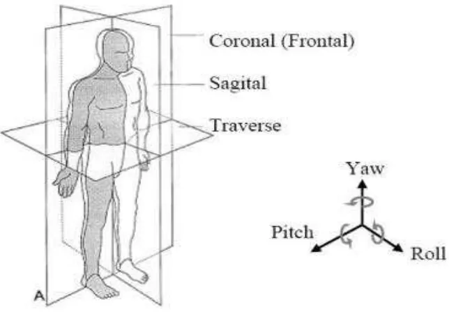
Human walking is in series with repeated motion in 3 dimensions. The hip exoskeleton unit should be able to accommodate the hip’s basic motions which are flexion and extension, abduction and adduction, and medial and lateral rotation (3-DOFmotion)[6]. For the understanding of human body’s joints, a Cartesian coordinate system can be used to display the relation of a human body.
Figure 4: Cartesian coordinate system
Sagittal Plane- Bisects the body from front to back, dividing it into right and left symmetrical halves. Movements which generally occur in this plane are flexion, extension, and hyperextension.
9
Transverse Plane- It is referred to as the horizontal plane divides the body horizontally into superior (upper) and inferior (lower) halves. Rotational movements such as spinal rotation and supination and pronation of the forearm occur in the transverse plane.[7]
For the thesis, the main focus is on the medial and lateral rotational of the lower limb. The rotational to the inner and outer is different in term of the limit of the maximum angle.
10 Anatomy of turning trajectory
2.1.3
Figure 6: Human Turning pattern
There are four phase in turning motion during walking[8] i.) Normal walking
ii.) Start to turn
iii.) Landing the swing foot iv.) Back to normal walking
There are two types of turning pattern generally during walking. Two types of turning pattern have different of turning angle.
11
Figure 8: Step turn pattern
2.1.3.1 Spin turn
This strategy allows the body to spin on the forward leg while producing a braking force (axial leg). The torso is kept behind the axial leg presumably to balance the centrifugal force caused by rotating the body and to step toward the new direction. As a result the subjects could not use this strategy after the COM passed the stance foot. The existence of push-off power is also advantageous to put spin on the body so the spin turn is restricted to less of the cycle than the step turn. [9]
2.1.3.2 Step turn