APPLICATION
MUHAMMAD SYADZA BIN SHARUDDIN
This Report Is Submitted In Partial Fulfillment of Requirements for the Bachelor Degree of Electronic Engineering (Industrial Electronics) with
Honors
Faculty of Electronic and Computer Engineering Universiti Teknikal Malaysia Melaka
ACKNOWLEDGEMENT
First of all, I am grateful and praised to Allah for the good health and wellbeing that were necessary to complete this research. Next, I have to thank my parents for their love and moral support thoughout my life. Thank you for giving me everything that I need. I wish to express my sincere thanks to my supervisor Dr. Norihan binti Abdul Hamid, lecturer of the Faculty of Electronic and Computer Engineering UTeM, for providing guidance, encouragement that is necessary to complete my project. I also would like to take this opportunity to express appreciation to all of the Department faculty members for their help and support. Last but not least, my sense of gratitude to one and all, who directly or indirectly help me.
ABSTRACT
ABSTRAK
CONTENTS
CHAPTER CONTENTS PAGE
PROJECT TITLE i
DECLARATION FORM ii
DEDICATION v
ACKNOWLEGEMENT vi
ABSTRACT vii
CONTENTS ix
LIST OF TABLES xiii
LIST OF FIGURE xiv
LIST OF ABBREVIATION xvi
LIST OF APPENDIX xvii
1 INTRODUCTION 1
1.2 Motivation of Research 2
2.4 Thermoelectric Generator 12
2.4.1 Thermoelectric Material 13
2.4.2 Thermoelectric Module 14
2.4.3 Thermoelectric System 14
2.5 Type of Energy Storage 15
2.5.1 Supercapacitor 16
2.5.2 Batteries 16
2.5.3 Different Battery vs Supercapacitor 17
2.6.1 Thermal Energy Harvesting For Small 19 Device Application
2.6.2 Architectural Thermal Energy Harvesting 19 Opportunities for Sustainable Computing 2.6.3 A Geothermal Thermo-Electric Energy 20
Converter for Charging Lithium-Ion Battery 2.6.4 Thermoelectric-Generator-Based DC-DC 20
Conversion Network for Automotive Applications
2.6.5 Thermal Energy Harvesting for WSN 21 2.6.6 High Efficiency Seebeck Thermoelectric 22
Device for Power System Design and Efficiency Calculations: A review of Potential Household Appliances
2.6.7 Waste Heat Energy Harvesting using 22 Thermoelectric Generator
2.6.8 Flexible Thermoelectric Generator for 22 Human Body Energy Harvesting
2.6.9 Energy Analyses of Thermoelectric 23 Renewable Energy Source
3 METHODOLOGY 24
3.1 Overview 24
3.2 Project Implementation 24
3.3 Flowchart of Project 25
3.3.1 Resistance Temperature Detector 29
3.3.2 Peltier Generator 29
3.4 Circuit Design and Development 31
3.4.1 Multisim 31
3.4.3 MAX757 32
3.4.4 Boost Converter 33
3.4.5 USB Port Module 34
3.4.6 Rechargeable AA Battery 35
4 RESULTS AND DISCUSSION 37
5 CONCLUSION AND RECOMMENDATION
5.1 Conclusion 52
5.2 Recommendation 53
REFERENCES 55
LIST OF TABLES
NO TITLE PAGE
2.1 Difference between battery and supercapacitor 17
2.2 Output power and output voltage for proposed TEG 23
3.1 Temperature difference and output voltage and current 30
4.1 Clothes iron temperatures 58
4.2 Electric kettle temperature 59
4.3 Air conditioner compressor unit temperature 59
LIST OF FIGURES
NO TITLE PAGE
2.1 Thermal energy transfer from high temperature to low 8
temperature in form heat.
2.2 Charge carriers flow in response to a temperature gradient. 10
2.3 Peltier effect. 11
2.4 How thermoelectric generator works. 12
2.5 Thermoelectric material 13
2.6 Thermoelectric module 14
2.7 Thermoelectric generator 15
2.8 Alkaline battery, Li-Ion battery and supercapacitor. 17
3.1 Block diagram of proposed circuit 25
3.2 Part 1 of project flowchart 27
3.3 Part 2 of project flowchart 28
3.5 TEG SP1848-2715 30
3.6 MAX757 IC circuit. 33
3.7 Boost converter 34
3.8 USB port module model YH11062B 35
3.9 GP AA rechargeable battery (1000mAh) 36
4.1 Temperature vs time graph for iron cloth. 38
4.2 Temperature vs time graph for electric kettle. 39
4.3 Bar chart of temperature of air conditioner compressor 40
unit and their brand.
4.4 Car’s body color and their temperature at noon. 41
4.5 MAX757 DC to DC step up circuit. 42
4.6 Fabricated MAX757 circuit. 42
4.7 Block diagram for charging phone and USB light. 43
4.8 Output circuit 44
4.9 Measuring output current when charging phone. 44
4.10 Phone is charging 45
4.15 Measuring current when charging batteries. 48
LIST OF ABBREVIATIONS
TEH - Thermal energy harvesting
TEG - Thermoelectric generator
RTD - Resistance Temperature Detector
DC - Direct current
AC - Alternating current
Emf - electromotive force
LED - Light emitting diode
USB - Universal Serial Bus
PCB - Printed Circuit Board
CAD - Computer Aided Design
Li-ion - Lithium-ion
RAM - rechargeable alkaline manganese
CPU - Central Processing Unit
LIST OF APPENDIX
APPENDIX TITLE PAGE
A Tables 58
B GP battery consumer manual 60
C MAX756/757 3.3V/5V/Adjustable-Output, 61
Step-Up DC-DC Converters
CHAPTER 1
INTRODUCTION
1.1 Introduction
cadmium, etc). The stored energy can be used to power up or charging electronic devices such as smartphone, mp3 player and also small lamp.
1.2 Motivation for Research
As mention in a book with a title "Enhanced thermoelectric performance of rough silicon and nanowires" by Hochbaum, Allon I, approximately 90% of the world’s electricity is generated by thermal energy, with 30–40% operating efficiency, power loss about 15 terawatts in the form of heat to the environment [1]. This thermal energy waste is actually can be used as a source of renewable energy to replace recent conventional electrical generator.
So this project expect to contribute the sustainability by providing a clean and environmental friendly way to generate electrical energy. Moreover, this project also aim in developing a low cost thermal energy harvesting device (prototype).
1.3 Objectives
The main objectives of this project are:
To identify the most suitable heat producing device that can supply thermal energy continuously or in a long period.
To develop an electric circuit for thermoelectric energy storage.
To design and develop a device that can store and step up the low output for an electronic device usage.
1.4 Problem Statement
1.5 Scope of Work
The scope of the project is set based on the objectives mentioned earlier in the thesis. Initially, the project scope covers on investigating an optimum thermal waste energy source that can serve as an input on the hot surface of the thermoelectric generator (TEG) to enable electrical energy generation. The thermal energy data is collected using Resistance Temperature Detector (RTD) PT100. RTD operate by changing its resistance value when the temperature changes. The resistance value will then be referred to RTD PT100 resistance to temperature table to define its temperature in degrees Celsius. Next, a way to boost or step up the low output current of TEG is explored. The types of integrated circuit or circuit which can step up or boost the low output is identified. After that, the type of storage suitable for the project is investigate to store the generated electrical energy. When all the data needed is completed, the circuit is tested on a breadboard. IF the circuit run successfully, the circuit is then designed using Proteus software before being fabricated using UV board. Simulation analysis of designed circuit will not be covered in the thesis because the IC used in the project, MAX757 was not found in any circuit simulation software. The tested circuit on breadboard consists of DC input voltage (TEG), DC-DC converter (booster), and a load (electronic devices). Once the test process on breadboard is done, a UV board circuit is fabricated based on the designed circuit. Thermoelectric generator (TEG), SP1848 is used to harvest thermal energy in order to produce electrical energy.
1.6 Thesis Outline
I. Chapter 1 - Introduction
This part explain about summary of this thesis and also the importance the project. This chapter also clarify the objectives, problem statement and also scope of project.
II. Chapter 2 – Literature Review
For this chapter, review of papers, book and journals related to thermal energy harvesting were done. All the theoretical part including the current knowledge topic which is based on secondary sources is explained in detail to understand about the project. The types of batteries for energy storage and how to increase electrical output is studied.
III. Chapter 3 – Methodology
In this part, the methodology explain on a systematic, theoretical analysis of the methods applied for the project. This chapter consists the theoretical analysis of the body of methods and principles associated with a branch of knowledge of the project such as thermoelectric concept, thermoelectric energy and others. The whole process was done based on flowchart constructed.
IV. Chapter 4 – Results and Discussion
V. Chapter 5 – Conclusion
CHAPTER 2
LITERATURE REVIEW
2.1 Overview
This chapter discussed about previous information which are from many sources such journal, book, past paper and etc. Moreover, this topic will explain the concept of thermal energy, thermoelectric, type of energy storage and step up converter.
2.2 Thermal Energy
particles. Thermal energy causing an object having a temperature which can be measured in degrees Celsius or Fahrenheit using a thermometer. The faster the particles move within an object or system, the higher the temperature recorded [3].
Thermal energy also can be understand when there is a difference between the temperature of the environment and a system within it, thermal energy is transferred between them as heat. An object or system does not have heat. Instead, as an object or system gains or loses heat, it increases or decreases its thermal energy.
Figure 2.1: Thermal energy transfer from high temperature to low temperature in form heat.
2.3 Thermoelectric
Thermoelectric is an effect where a direct conversion of temperature difference to voltage and vice versa. Conversely, when a voltage is applied to it, it creates a temperature difference. A temperature gradient causes charge carriers in a material to diffuse from the hot side to the cold side. This effect can be used to generate electricity, measure temperature or change the temperature of objects [5]. Because the direction of heating and cooling is determined by the polarity of the applied voltage, thermoelectric devices can be used as temperature controllers. Thermoelectric effect can be divided into three which are; Seebeck effect, Peltier effect, and Thomson effect.
2.3.1 Seebeck Effect
Seebeck effect can be explain, when there is a temperature difference, diffusion of electrons from the hot side to the cold side of a conductor will occur. The motion of electrons creates an electrical current. When a conductive material is subjected to a thermal gradient, charge carriers migrate along the gradient from hot to cold. In the open-circuit condition, charge carriers will accumulate in the cold region, resulting in the formation of an electric potential difference. The Seebeck effect describes how a temperature difference creates charge flow. Electrons transfer heat in two ways:
Figure 2.2: Charge carriers flow in response to a temperature gradient.
In figure above, thermal energy flow from hot side to cold side.
The Seebeck effect is an example of an electromotive force (emf) which leads to measurable currents or voltages. Electromotive forces modify Ohm's law by generating currents even in the absence of voltage differences (or vice versa); the local current density is given by:
Where:
J is the local current density.
is the local voltage and is the local conductivity.
Eemf is the electromotive force.
In general, the Seebeck effect is described locally by the creation of an electromotive field:
Where:
is the Seebeck coefficient, a property of the local material.
2.3.2 Peltier Effect
The Peltier effect is the presence of heating or cooling at an electrified junction of two different conductors. When a current is made to flow through a junction between two conductors A and B, heat may be generated or removed at the junction. The Peltier heat generated at the junction per unit time, , is equal to:
Where:
( ) is the Peltier coefficient of conductor A (B).
is the electric current (from A to B).
The junctions of dissimilar metals were heated or cooled, depending upon the direction in which an electrical current passed through them. Heat generated by current flowing in one direction was absorbed if the current was reversed.
2.3.3 Thomson Effect
Thomson effect describes the heating or cooling of a current-carrying conductor with a temperature gradient. This Thomson effect was predicted and subsequently observed by Lord Kelvin in 1851.
If a current density is passed through a homogeneous conductor, the Thomson effect predicts a heat production rate per unit volume of:
Where:
is the temperature gradient.
is the Thomson coefficient.
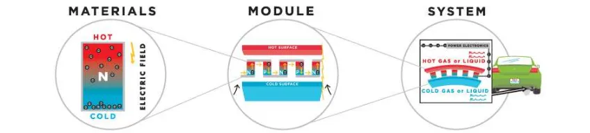
2.4 Thermoelectric Generator
Thermoelectric generator process can be divided into three which are thermoelectric material, thermoelectric module and thermoelectric system.
2.4.1 Thermoelectric Material
Figure 2.5: Thermoelectric material.
2.4.2 Thermoelectric Module
Figure 2.6: Thermoelectric module.
A circuit comprising thermoelectric materials that output usable electricity is called thermoelectric module. A thermoelectric module for power generation must work in a very large temperature gradient and consequently be exposed to large thermally induced stresses and strains for long periods of time. They must also be able to withstand a large number of thermal cycles, which cause mechanical fatigue. A thermoelectric module requires two thermoelectric materials to function: one, an n-type (negatively charged) semiconductor; the second, a p-type (positively charged) semiconductor. The module is designed this way so that a continuous circuit can be made whereby current can flow and power can be produced. With only one type of thermoelectric material, a voltage would be induced but current would never flow.
2.4.3 Thermoelectric System
air, water or another suitable medium. To supply this heating and cooling, technologies known as heat exchangers are used on both the hot and cold sides [7]. A thermoelectric power generation system can be thought of as two heat exchangers, each of which have to move heat to (or from) the hot (or cold) side of the thermoelectric modules. A thermoelectric generator produces AC power only after the original DC power from the thermoelectric modules passes through an inverter. An integrated power electronics system is necessary to deliver AC power to the customer.
Figure 2.7: Thermoelectric generator.
2.5 Type of Energy Storage
2.5.1 Supercapacitor
A supercapacitor is a high-capacity electrochemical with capacitance values in the range of around 100000 uF up to 1000 F with rated voltage of 1.2V up to 3.8V. A supercapacitor consists of two or more conductive plates separated by a dielectric. When an electric current enters a supercapacitor, the dielectric stops the flow and a charge builds up and is stored in an electric field between the plates.
2.5.2 Batteries
A battery is an electrochemical cell that can be charged electrically to provide a static potential for power or released electrical charge when needed. The chemical unit contains three main parts; a positive terminal called the cathode, negative terminal called the anode, and the electrolyte. The battery charges and discharges through a chemical reaction that generates a voltage. The battery is able to produce a constant stream of electricity that can be turned on and off.
a) Lithium-ion Battery (Li-ion)
A lithium-ion battery is one type of rechargeable battery in which lithium ions move from the negative electrode to the positive electrode during discharge and back when charging.
b) Rechargeable alkaline battery
Figure 2.8: Alkaline battery, Li-Ion battery and supercapacitor.
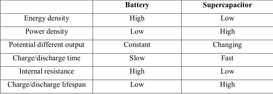
2.5.3 Different Battery vs Supercapacitor
Battery and supercapacitor have their own advantage and disadvantage. Table below shows the difference between battery (LI-ion/Alkaline) and supercapacitor.
Table 2.1: Difference between battery and supercapacitor.
Battery Supercapacitor
Energy density High Low
Power density Low High
Potential different output Constant Changing
Charge/discharge time Slow Fast
Internal resistance High Low
Batteries have a higher energy density meaning they can store more energy per unit mass, but supercapacitors have a higher power density, which they can release energy more quickly. That makes supercapacitors particularly suitable for storing and releasing large amounts of power relatively quickly, but batteries are used for storing large amounts of energy over long periods of time.
Even though supercapacitors work at relatively low voltages about 2–3 volts, they can be connected in series to produce bigger voltages for use in more powerful equipment. Supercapacitor have little or no internal resistance, which means they store and release energy without using much energy and work at very close to 100 percent efficiency.
Moreover, a supercapacitor typically store about 10 to 100 times more energy per unit volume or mass than normal capacitors, can charge and discharge faster than batteries. Furthermore, it can tolerate many more charge and discharge cycles than rechargeable batteries.
2.6 Journal Reviews
2.6.1 Thermal Energy Harvesting For Small Device Application
Project done by Nurul Husna Mohd (2015) show the sources of thermal energy was investigated from various source such as jug kettle, clothes iron, heat from laptops, and hair drier. The output voltage recorded from the TEG is 0.89V harvested from clothes iron as input. The harvested electricity is serve as an input for MAX757 voltage regulator IC which also act as voltage booster. The output from the IC is 3.98V voltage with 40.2mA current. The input is used to power up LED diode.
2.6.2 Architectural Thermal Energy HarvestingOpportunities for Sustainable Computing
2.6.3 A Geothermal Thermo-Electric EnergyConverter for Charging Lithium-Ion Battery
O. M. Neamţu on 2014 studies about the optimal conditions for thermal power conversion system. Geothermal water source heat is used as a source for TEG application. This paper also investigate in ensuring the energy conversion in combination with storage Li-Ion battery [9]. Matlab-Simulink program is used to design and simulate the thermal energy harvesting and storing circuit. The thermoelectric generator is modeled in the simulation as a random source. An efficient electronic energy transfer DC-DC converter were applied to determine the optimal storage batteries. TEG. TGMT-19W-4V which is a type of TEG were used to harvest thermal energy. The results shows that, the water temperature recorded from geothermal wells located in the University of Oradea is about 82°C to 87°C. 16 cells TGMT-19W-4V is mounted and they provides a power of about 32W. The maximum output voltage recorded is 28V output voltage.
2.6.4 Thermoelectric-Generator-Based DC-DC Conversion Network for Automotive Applications
(18V input). The results shows that when the Rteg of TEG module and the Rin of
converter are matched, the delivery efficiency is 50% and the power delivered to the converter is maximized, the number of TE couples needed is 56; while the available Vin
for converters at EGR and EGP are approximately 5.9 V and 4.8 V respectively. The achieved overall efficiency for both locations under average scenario is 3.8%. In parallel TEG modules, the two-level conversion network can achieve even higher thermal power utilization than the single-stage system, while having higher overall efficiency [10].
2.6.5 Thermal Energy Harvesting for WSN
2.6.6 High Efficiency Seebeck Thermoelectric Device for Power System Design and Efficiency Calculations: A review of Potential Household Appliances.
Journal by T Stephan John (2014), he proposed a system to harvest thermal energy while cooking with gas stove [12]. The system which consist of few main component which are TEG, tin stand, water supply, pipes, heat sink, gas stove, cook ware, multimeter and thermometer. The idea is to use tin to collect thermal energy when the gas stove is on. The TEG will put on the tin surface to convert it to electrical energy. Based on the result, the highest output was 7.1V voltage, 0.82A current and 5.822W power from 2 TEGs connected in series.
2.6.7 Waste Heat Energy Harvesting using Thermoelectric Generator.
The journal by A. Jacks delightous Peter, Balaji. D, and D. Gowrishankar on July 2013 explained about harvesting waste heat energy using TEG [13]. Based on the journal, the TEG consist of 4 main components which are TEG module, TEG shield, thermal fin and copper electrode. They proposed some improvements for the TEG to produce a higher output (power and voltage) such as increasing the thermal gradient value by using larger fin, coupling more TEG in series and use different type of material for the TEG itself.
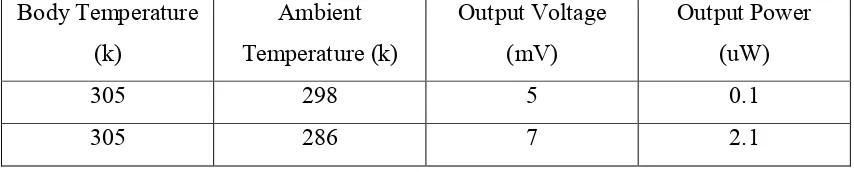
2.6.8 Flexible Thermoelectric Generator for Human Body Energy Harvesting.
Published on 2nd August 2012, written by S.E. Jo, M.K. Kim, M.S. Kim and Y.J.
Table 2.2: Output power and output voltage for proposed TEG.
2.6.9 Energy Analyses of Thermoelectric Renewable Energy Source.
CHAPTER 3
METHODOLOGY
3.1 Overview
This part discussed on how to collect information and data for the project. The steps and procedures are also explained in detail to ensure the project runs smoothly
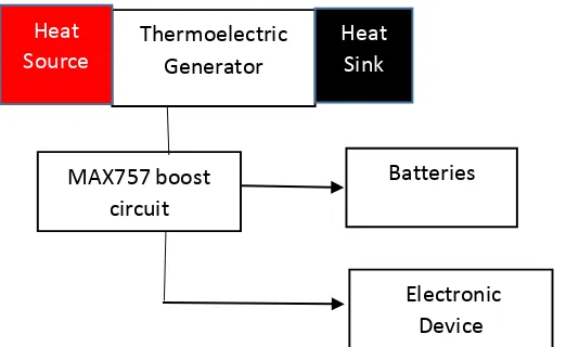
3.2 Project Implementation
Figure 3.1: Block diagram of propose circuit
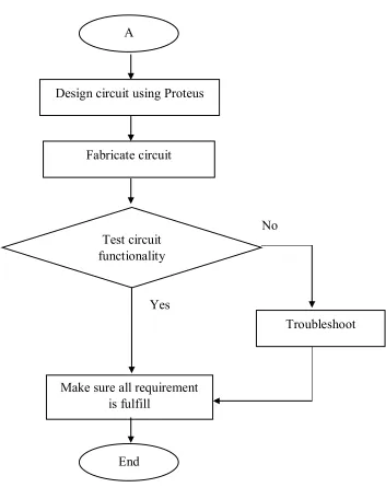
3.3 Flowchart of Project
Figure 3.2 shows the overall project flowchart starting from semester 1 until semester 2. Based on the project title, Thermal Energy Harvesting for Electronic Device Application, the first thing to do is study and understand about the thermal energy harvesting which is based on the concept of thermoelectric. Next, based on the objective, a most suitable heat producing device that can supply thermal waste energy continuously or in a long period need to be identified. Various thermal waste energy is identified and investigated by measuring the temperature or heat released by the devices such as clothes iron, kettle and air conditioner using a device called Resistance Temperature Detector (RTD).
needed, block diagram is produced and circuit is designed. The designed circuit is tested on breadboard. It is important to make sure the proposed circuit is acceptable or passed before fabricating the circuit.
Figure 3.3: Overall project flowchart.
Figure 3.3: Part 2 of project flowchart. Fabricate circuit
A
Test circuit functionality
Yes
No
Troubleshoot
Make sure all requirement is fulfill
End
3.3.1 Resistance Temperature Detector
Resistance temperature detectors (RTDs), is a sensor used to measure temperature by correlating the resistance of the RTD element with temperature. Most RTD elements consist of a length of fine coiled wire wrapped around a ceramic or glass core. The RTD element is made from a pure material such as platinum, nickel or copper. The material resistance changes as the temperature changes and it is this change that is used to determine temperature. RTD is constructed in a number of forms and offer greater stability, accuracy and repeatability in some cases than thermocouples. While thermocouples use the Seebeck effect to generate a voltage, resistance thermometers use electrical resistance and require a power source to operate.
Figure 3.4: Resistance Temperature Detector
3.3.2 Peltier Generator
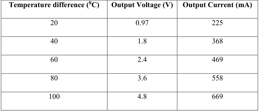
dissipate faster in order to create a large temperature difference between the two sides. The TEG used for this project is TEG-SP1848-2715. The specification for the TEG:
Temperature range: -40 to 120 degrees Celsius Output voltage: 0 to 4.8V
Table 3.1: Temperature difference and output voltage and current.
Temperature difference (0C) Output Voltage (V) Output Current (mA)
20 0.97 225
40 1.8 368
60 2.4 469
80 3.6 558
100 4.8 669
3.4 Circuit Design and Development
When all the information is investigated and discussed, a circuit is proposed which consist of several electronic components. The circuit is simulate using simulation software before a prototype is done.
3.4.1 Multisim
Multisim is an electronic schematic capture and simulation program which is part of a suite of circuit design program. It is considered as a Computer aided design (CAD) tool that help user to construct or design electronic circuits. Multisim is one of the few circuit design programs to employ the original Berkeley SPICE based software simulation. Multisim includes microcontroller simulation as well as integrated import and export features to the Printed Circuit Board layout software in the suite. At the time it was mainly used as an educational tool to teach electronics technician and electronics engineering programs in colleges and universities. National Instruments has maintained this educational legacy, with a specific version of Multisim with features developed for teaching electronics. Multisim is widely used in academia and industry for circuit education, electronic schematic design and SPICE simulation.
3.4.2 Proteus
microcontrollers in the software. Proteus is a CAD tool to test programs and embedded designs. User can simulate your programming of microcontroller in Proteus software. Once simulating circuit in Proteus Software is done, user can directly make PCB design with it. The tools in this software are very easy to use and very useful in education and professional PCB designing. As professional PCB designing software with integrated space based auto router, it provides features such as fully featured schematic capture, highly configurable design rules, interactive SPICE circuit simulator, extensive support for power planes, industry standard CADCAM & ODB++ output and integrated 3D viewer.
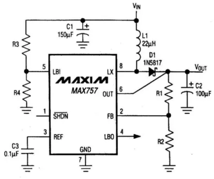
3.4.3 MAX757
MAX757 is a CMOS step-up DC-DC switching regulators for small input voltage. [11] The MAX757 is an adjustable IC that accepts an input voltage as low as 0.7V and produces a higher adjustable output voltage in the range from 2.7V to 5.5V. The full-load efficiencies for the MAX757 is greater than 87%. The key features of MAX757 IC:
Operates Down to 0.7V Input Supply Voltage 87% Efficiency at 200mA
60µA Quiescent Current
20µA Shutdown Mode with Active Reference and LBI Detector 500kHz Maximum Switching Frequency
±1.5% Reference Tolerance Over Temperature Low-Battery Detector (LBI/LBO)
Figure 3.6: MAX757 IC circuit.
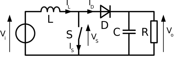
3.4.4 Boost Converter
A boost converter or a step-up converter is a DC-to-DC power converter with an output voltage greater than its input voltage. It is a class of switched-mode power supply (SMPS) containing at least two semiconductors (a diode and a transistor) and at least one energy storage element, a capacitor, inductor, or the two in combination. Filters made of capacitors (sometimes in combination with inductors) are normally added to the output of the converter to reduce output voltage ripple.
Operating principle:
2. When the switch is opened, current will be reduced as the impedance is higher. The magnetic field previously created will be destroyed to maintain the current towards the load. Thus the polarity will be reversed (means left side of inductor will be negative now). As a result two sources will be in series causing a higher voltage to charge the capacitor through the diode D.
Figure 3.7: Boost converter.
3.4.5 USB Port Module
USB port module is a component that receives input voltage and regulate it to a certain value. The model used in the project is YH11062B. The mini USB produces 5 volts DC voltage regulator with continuous LED. It can receives a DC input of 2.6 to 5V voltages and 0 to 2A current. The specification of the USB port module is as follows:
Operating Temperature: -20°c to +80°c Voltage regulation: ± 2.5%
Short circuit protection: Yes
Input Reverse Polarity Protection: None
Figure 3.8: USB port module model YH11062B
3.4.6 Rechargeable AA battery
The rechargeable batteries used for the project are GP rechargeable AA battery. The battery is a nickel-metal hydride battery. The batteries can store about 950mAh capacity. It can be charge and discharge nearly about 300 times. It can be used for light household devices such as alarm clock, radio, remote controller and other small electronic devices.
Features:
Nominal voltage 1.2V Gross weight ~15.2g
Battery handling:
Batteries should be charged prior to use.
Remove batteries from the electrical device if the device is not going to be used for a long period of time.
In order to maintain satisfactory cell or battery performance when being stored under extending period of time, fully charge the battery within 12 months period is highly recommended.
CHAPTER 4
RESULTS AND DISCUSSION
4.1 Overview
4.2 Sources of Thermal Energy
Thermal waste energy data is collected from various source such as clothes iron, electric kettle, air conditioner, and also car’s body temperature. The temperature is measured using a device called Resistance Temperature Detector (RTD). The RTD will change its resistance value when temperature is changes. The resistance value collected is taken after a certain period of time. The resistance value is changed to temperature value in degrees Celsius based on the RTD PT100 table.
4.2.1 Clothes Iron
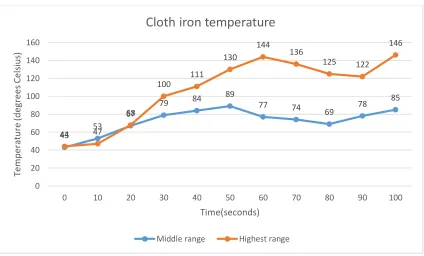
Figure 4.1: Temperature vs time graph for iron cloth.
Based on table 4.1 in appendix, the resistance value is taken for every 10 seconds period until 100 seconds. The cloth iron was set with two ranges, the middle
range and highest range. Figure 4.1 shows the line graph of temperature versus time. From the graph, the temperature increases as time increases until a certain level. The maximum value measured for middle range was 134.4 Ohms which is equal to 84 degrees Celsius while the maximum value measured for highest range was 155.7 Ohms which is equal to 146 degrees Celsius. The temperature is changing because clothes iron operates by increasing its temperature until a desired temperature. After that, no temperature is applied to the iron surface for a certain period of time causing temperature to drop. Then, after a period of time, the clothes iron temperature is increased again. This process will repeat until the power is off.
4.2.2 Electric Kettle
Figure 4.2: Temperature vs time graph for electric kettle.
Table 4.2 in appendix shows the temperature of electric kettle in a period of every 30 seconds when boiling 1.7 litre of water. The time taken to boil water is 390 seconds which is equal to 6.5 minutes. As shown in the graph 4.2, the temperature of electric kettle increase steadily until the final or maximum temperature reading is 84 degrees Celsius.
4.2.3 Air Conditioner
Figure 4.3: Bar chart of temperature of air conditioner compressor unit and their brand.
In table 4.3 and chart in figure 4.3, shows the temperature of two brands of air conditioner. Mitsubishi air conditioner compressor unit shows a higher temperature which is 50 degrees Celsius, means that it generate more thermal energy waste.
4.2.4 Car’s Body Temperature at Noon
Figure 4.4: Car’s body color and their temperature at noon.
Three different color of car is used to measure the temperature exposed under sunlight at twelve noon which are white, silver and black. It shows that, the temperature is highest when the color is black. This is due to black color absorb large amount of sunlight while white or shining color deflect sunlight.
4.3 Experimental Set-up
After achieving all the information needed, an experiment was set up. Circuit in figure 4.5 is for IC MAX757 DC to DC step up voltage. The circuit needs a minimum of 0.7V voltage input to turns on or enables the step up voltage function. The Led in the
circuit is an indicator to shows that the voltage input was step up or boost to a higher value.
Figure 4.5: MAX757 DC to DC step up circuit.
Figure 4.6: Fabricated MAX757 circuit.
Figure 4.7: Block diagram for charging phone and USB light.
Figure 4.8: Output circuit construction.
4.4 Experimental Result
After the circuit is fabricated, the circuit was tested to collect experimental data. Data was collected when given input from electric kettle and cloth iron.
The highest output voltage from the MAX757 was 7.86V. Figure 4.9 shows the measuring of current when a phone is charging. Due to the inconstant thermal source temperature level, the current reading was varied and the highest current measured was 23mA. The voltage measured is as an input to the phone was 6.64V. There was a voltage drop when output voltage from MAX757 circuit is given to the USB port module which is about 1.22V.
Figure 4.10: Phone is charging.
Figure 4.11: Circuit is connected to USB Led light.
The circuit is also tested to turn on a USB Led light as shown in Figure 4.11. The USB Led light turn on as shown on Figure 4.12. The voltage supplied by the MAX757 circuit and USB port module was 3.16V and the current measured was 38mA.
Figure 4.13: Measuring current when powering USB Led Light.
Figure 4.14: Circuit does not turn on when TEG is given heat from electric kettle.
Figure 4.15: Measuring current when charging batteries.
The output of the MAX757 is then being used to charge 4 rechargeable batteries. 4 rechargeable batteries is used because the output of the MAX757 circuit is set to have highest current available. The voltage output according to the batteries was 1.2V each which in total should be 4.8V. The measured voltage of the batteries was 5.2V. The important thing before connecting the circuit to the batteries is to add a diode to prevent current flow from batteries to the MAX757 circuit. The current measured when charging was 26.5mA.
4.5 Discussion
Figure 4.17: Heat sources and highest temperatures.
Next, the thermal energy source from cloth iron at middle range and electric kettle is used to supply thermal energy to the TEG. When the TEG is put on the hot surface of cloth iron, the MAX757 circuit was turned on. However, when the TEG was put on the hot surface of electric kettle, the MAX757 does not turned on. The MAX757 IC needs a minimum of 0.7V to be turned on. It was discovered that the voltage provide by TEG when put on the surface of electric kettle was only 0.5V while for the cloth iron was 1.1V. The insufficient voltage when using electric kettle as thermal energy source causing the MAX757 IC cannot be turned on. Thus, the cloth iron at middle range is the most suitable heat source to power up the MAX757 circuit.
Moreover, a phone was charged at the USB port. The phone need at least 5V power in order to start charging. The output voltage of the MAX757 when using cloth iron as heat source was 7.86V. The circuit was then connected to the USB port module to charge a phone, the voltage decreases to 6.64V. The measured current was really small which was 23mA. Next, the circuit was connected to a USB Led light. The USB Led light turned on brightly.
CHAPTER 5
CONCLUSION AND RECOMMENDATION
5.1 Conclusion
As a conclusion, there are several thermal energy sources has been investigates on to produce electrical energy over a long period. The thermal energy source from cloth iron at middle range is the most suitable to power up electronic device application because it provides high thermal energy compared to electric kettle, car’s body temperature and air conditioner compressor unit. The highest temperature from cloth iron was 89 degrees Celsius and it produces voltage output of 1.1V.
Finally, a device that can store and step up the low output of the thermoelectric generator was developed for electronic device usage. MAX757 was used to step up the voltage and current of the thermoelectric generator. The output voltage from thermoelectric generator was boost from 1.1V to 7.86V but the current produced was 23mA and does not increases. The output of the circuit was used to power up USB Led light and to charge a phone.
In overall, the circuit for thermal energy harvesting was successfully developed. The circuit can store generated electrical energy and the output power also can be used to power up small electronic devices (5V).
5.2 Recommendation
Based on the project conducted, it is recommended to find a suitable thermal energy source to be apply on the thermoelectric generator. Low temperature of thermal energy source will produce only small amount of electrical energy but it is important to check the highest temperature the TEG can endure. If input temperature exceed the highest temperature of TEG can tolerate, the TEG will be broken and cannot be used anymore.
REFERENCES
[1] A. Hochbaum, R. Chen, R. Delgado, W. Liang, E. Garnett, M. Najarian, A. Majumdar and P. Yang, "ChemInform Abstract: Enhanced Thermoelectric Performance of Rough Silicon Nanowires.", ChemInform, vol. 39, no. 14, 2008. [2] N. Husna, “Thermal Energy Harvesting For Small Device Application”, 2015. [3] "What is Thermal Energy? - Definition & Examples - Video & Lesson
Transcript | Study.com", Study.com, 2016. [Online]. Available:
http://study.com/academy/lesson/what-is-thermal-energy-definition-examples.html.
[4] "Thermodynamics and Thermal Energy", BURN An Energy Journal, 2012. [Online]. Available: http://burnanenergyjournal.com/thermodynamics-and-thermal-energy-2/.
[5] J. Baeyens, "Waste Energy Harvesting: Mechanical and Thermal Energies. By Ling Bing Kong, Tao Li, Huey Hoon Hng, Freddy Boey, Tianshu Zhang, and Sean Li", Energy Technology, vol. 3, no. 7, pp. 790-790, 2015.
[6] https://www.alphabetenergy.com/how-thermoelectrics-work/
[7] Liu C., Chen P., Li. K. “A 1 KW Thermoelectric Generator for Low-temperature Geothermal Resources”, 2014.
[9] O. M. Neamţu , “A Geothermal Thermo-Electric Energy Converter for Charging Lithium-Ion Battery”, 2014.
[10] M. Li, S. Xu, Q. Chen and L. Zheng, "Thermoelectric-Generator-Based DC–DC Conversion Networks for Automotive Applications", Journal of Electronic Materials, vol. 40, no. 5, pp. 1136-1143, 2011.
[11] Xin Lu, “Thermal Energy Harvesting for WSN", 2011.
[12] T. StephenJohn, "High Efficient Seebeck Thermoelectric Device for Power System Design and Efficiency Calculation: A Review of Potential Household Appliances", International Journal of Computer Applications, vol. 97, no. 18, pp. 37-42, 2014.
[13] A. Delightus Peter, "Waste heat energy harvesting using thermo electric generator",IOSR Journal of Engineering, vol. 3, no. 7, pp. 01-04, 2013.
[14] S. Jo, M. Kim, M. Kim and Y. Kim, "Flexible thermoelectric generator for human body heat energy harvesting", Electronics Letters, vol. 48, no. 16, pp. 1015-1017, 2012.
[15] Jarman, E. Khalil and E. Khalaf, "Energy Analyses of Thermoelectric Renewable Energy Sources", OJEE, vol. 02, no. 04, pp. 143-153, 2013.
[16] "How do supercapacitors work?” Explain that Stuff, 2016. [Online]. Available: http://www.explainthatstuff.com/how-supercapacitors-work.html.
[17] "Supercapacitor Information – Battery University", Batteryuniversity.com,
2016. [Online]. Available:
http://batteryuniversity.com/learn/article/whats_the_role_of_the_supercapacitor. [18] O. Högblom and R. Andersson, "Analysis of Thermoelectric Generator Performance by Use of Simulations and Experiments", Journal of Electronic Materials, vol. 43, no. 6, pp. 2247-2254, 2014.
[19] L. Baranowski, G. Jeffrey Snyder and E. Toberer, "Effective thermal conductivity in thermoelectric materials", J. Appl. Phys., vol. 113, no. 20, p. 204904, 2013.
[21] A. Polozine, S. Sirotinskaya and L. Schaeffer, "History of development of thermoelectric materials for electric power generation and criteria of their quality", Mat. Res., vol. 17, no. 5, pp. 1260-1267, 2014.
[22] S. LeBlanc, S. Yee, M. Scullin, C. Dames and K. Goodson, "Material and manufacturing cost considerations for thermoelectrics", Renewable and Sustainable Energy Reviews, vol. 32, pp. 313-327, 2014.
[23] A. Perez-Marín, A. Lopeandía, L. Abad, P. Ferrando-Villaba, G. Garcia, A. Lopez, F. Muñoz-Pascual and J. Rodríguez-Viejo, "Micropower thermoelectric generator from thin Si membranes", Nano Energy, vol. 4, pp. 73-80, 2014. [24] M. Yang, C. Wu, C. Dai and W. Tsai, "Energy Harvesting Thermoelectric
Table 4.2: Electric kettle temperature.
Time (s) Average Resistance for 3 Trial (Ω)
Table 4.3: Air conditioner compressor unit temperature.
Brands Average resistance (Ω) Temperature (degrees Celsius)
York 115.8 41
Mitsubishi 119.4 50
Table 4.4: Car’s body temperature.
Color Average resistance (Ω) Temperature (degrees Celsius)
Silver 114.9 38
Black 121.1 54