DECLARATION
“I declare this report is on my own work except for summary and quotes that I have mentioned its sources”
Signature :
Name of Author : AHMAD FITRI BIN SUKARMAN
APPROVAL
This report is submitted to the Faculty of Manufacturing Engineering of UTeM as a partial fulfillment of the requirement for the degree of Bachelor of Manufacturing Engineering (Manufacturing Design) with honours. The member of the supervisory committee is as follow:
i
ABSTRACT
ii
ABSTRAK
vi
4.4.2 Product Structure Worksheet 59
4.4.3 DFA Analysis 60
4.4.4 DFM Analysis 63
4.4.5 DFMA Analysis 67
4.5 Comparison between Original Design and Improved Design 69
4.5.1 Parts Design 69
4.5.2 DFMA Analysis Result 72
5. CONCLUSION AND RECOMMENDATION 75
5.1 Conclusion 75
5.2 Recommendation 76
REFERENCES 77
LIST OF TABLES
2.1 Lucas DFA method – Manual Handling Analysis 14
2.2 Lucas DFA method – Manual Fitting Analysis 15
2.3 Worksheet analysis for manual assembly 20
2.4 Worksheet for automatic assembly analysis 22
3.1 Gantt chart for PSM 1 42
3.2 Gantt chart for PSM 2 43
4.1 Bills of Material (BOM) of Steering Wheel Lock 45
4.2 Example of DFA analysis of Steering Wheel Lock 51
4.3 DFA Analysis result for original design 52
4.5 DFMA analysis for original design 55
4.6 Suggestion for Redesign 56
4.7 Example of DFA analysis of Steering Wheel Lock 60
4.8 DFA analysis result for improved design 61
4.9 DFM Concurrent Costing Analysis Result 64
4.10 DFMA analysis for improved design 68
4.11 Comparison of DFMA Analysis for both original design and improved design of steering wheel lock 72
LIST OF ABRREVIATIONS
DFE - Design for Environment DFS - Design for Sustainability DFC - Design for Cleaning
DFMA - Design for Manufacturing and Assembly ECN - Engineering Change Notice
Ci - Cost of automation insertion
NM - Minimum number of parts FMEA - Failure Modes and Effects Analysis DTC - Design to Target Cost
x
LIST OF APPENDICES
A Manual Handling Chart B Manual Insertion Chart
C The classification system and database for a single-station one-arm robot assembly system
D DFA Guideline
1
CHAPTER 1
INTRODUCTION
The first chapter of this report presents the general idea of the project. It is include five sections in this chapter which is background, problem statement, objectives, research methodology, and scope of the project. The background section presents an introduction about manufacturing design. Certain problems of product design and the problems that attempt to address in this project will state in problem statement section. The target of this project is present in objective section. The last part in this chapter is scope of the project which elaboration from the objectives section.
1.1 BACKGROUND
Nowadays, people are more demanding on something that simple and less costly in their daily requirement. In order to meet customer needs, more companies struggling with competitive markets to produce low cost products with high quality and faster to market. Many researches have been carried out that focusing on increasing the efficiency and simplify the operation especially both assembly and manufacturing process and cost.
2
There are some techniques and tools that can be used to sustain the creativity and to help designers or manufacturers to think logically so that the design specifications are organized and smart development. Engineering design can be rewritten as organized and smart development and estimation of detail description for new objects that have specific shape and geometry and brings some special purpose that reaches the goal without going against any particular restrictions.
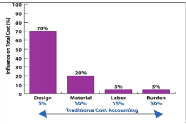
Improvement in many company’s operation is made by using a specific method. Usually, in industry the improvement they made are based on reduction cost. The reduction of cost could be made in early stage of design cycle. This is mean that cost estimation is an essential aspect in design stage. Moreover, this is accepted that over 70% of final product costs are determined during design stage which is shown in Figure 1.1 (Boothroyd, 2002).
Figure 1.1: Influence of product design in the product development (Boothroyd et al.,
3
In the past, design and manufacturing exist independently which is sequential approach to design the product. In sequential approach, a number of distinct phases are divided. A product flows from one department in an organization to another and possible to repeat to ensure that the product will still function adequately (Kalpakjian and Schmid, 2006).
The design process begins with generation of a product concept (Kalpakjian and Schmid, 2006). Innovative and creativity is greatly needed at this stage to lead to major savings in material and production costs. Understanding of the functions and the performance expected of the product is required in the design stage.
There are various design guidelines are available which has known as Design for X. Each design guideline addresses a particular issue that is caused by, or affects the characteristics of a product. The design guidelines itself propose usually an approach and corresponding methods that may help to generate and apply technical knowledge in order to control, improve, or even to invent particular characteristics of a product. X represents anything such as Design for Environment (DFE), Design for Sustainability (DFS), Design for Cleaning (DFC) and many more. Among of them is Design for Manufacturing and Assembly (DFMA).
4
1.2 PROBLEM STATEMENT
The automobile has always been considered one of the most convenient forms of transportation available to human, whether from home to work, or for shopping. It is one of the most essential vehicles in our daily life. But recently, many vehicle reported has been stolen easily. Therefore, this situation causes the development of antitheft device. A lots of antitheft device has been manufactured such as gear shift lock, break lock, door lock and among these are steering wheel lock which is more popular in the market. However, the design of existing steering wheel lock in the market is quite complicated and causes the manufacturing process and components in the design of a product cannot maximize to be used. Thus, finding better method to manufacture steering wheel lock would be a step towards to design better steering wheel lock.
In order to design a better steering lock, DFMA should be applied in the design of steering lock to obtain the maximum benefit from DFMA. Many examples proved that DFMA analysis is the key to very significant reductions in overall manufacturing cost. Thus, this project will use DFMA method to investigate and redesign the current product which is steering wheel lock.
1.3 OBJECTIVE
The objectives of this project are:
a) To analysis of current product of antitheft device system which is steering lock based on DFMA analysis.
b) To integrate DFMA tools into product design and development process.
5
1.4 SCOPE
6
CHAPTER 2
LITERATURE REVIEW
In this chapter, literature review on Design for Manufacturing and Assembly (DFMA) method are explained. There are certain important DFMA tools that have been applied such as Design for Assembly (DFA) and Design for Manufacture (DFM). This chapter described about the definition of Design for Manufacturing and Assembly (DFMA), Boothroyd Dewhurst DFA method, the Lucas DFA method, the application engineering software called DFMA Software and current product which are car padlock systems.
2.1 Previous Design Method
During new product development, combination team of engineers and management (mechanical engineer, electrical engineer, production engineer, sale people and management) to generate the product, has proven to lower the product cost, improve product quality and decrease the development time. In fact, traditionally, the design engineer and manufacturing engineer work individually that is the design engineers have to concept of “we design it, you build it” (Boothroyd et al., 2002).
7
However, once there is a design change made by other department, the design analysis stage has to be repeated leading to product development delay because waiting for the engineering change notice (ECN) to be approved by designer (Kalpakjian and Schimid, 2006).
By using this method, resources, money and more importantly, time is wasted. Moreover, this conventional product development faces major difficulties that are design paradox as shown in Figure 2.1. Design paradox can be determined as the correlation between the designer knowledge about the product and the number of actions to be made during the product development cycle (Bramley et al., 2005).
8
2.2 Design for Manufacturing and Assembly (DFMA)
Design for Manufacturing and Assembly (DFMA) is a design philosophy used by designers when a reduction in part counts, a reduction in assembly time, or a simplification of subassemblies is desired. It can be used in any environment regardless of how complex the part is or how technologically advanced this environment may be. DFMA encourages concurrent engineering during product design so that the product qualities reside with both designers and the other members of the developing team (D-ESPAT, 2007).
The term “DFMA” comes with the combination of DFM (Design for Manufacturing) and DFA (Design for Assembly). DFA means the design of the product for ease of assembly while DFM gives mean the designs for ease manufacture of the collection of parts that will form the product after assembly process (Boothroyd et al., 2002).
The objective using of DFMA is to minimize the number of parts count in an assembly or product and to maximize the use of manufacturing process. It is described that DFMA is an organized procedure for analyzing proposed designs from the perspective of assembly process (Edwards, 2002).
The basic concept of it is that the design engineers apply the DFMA paradigm or software to analyze the manufacturing and assembly problems at the early design stage. By this means, all of considerations about the factors that affect the final outputs occur as early as possible in the design cycle. The extra time spent in the early design stage is much less the time that will be spent in the repeatedly redesign. Meanwhile, the cost will be reduced (Xiaofan Xie, 2004).
9
2.2.1 History of Design for Manufacturing and Assembly (DFMA)
According to Geoffrey Boothroyd, Professor of Industrial and Manufacturing at the University of Rhode Island, the practices now known as Design for Assembly (DFA), and Design for Manufacture (DFM) had started in the late 1970’s at the University of Massachusetts USA. With this issue, industry was most interested in Design for Assembly. When developing a product, the maximum potential cannot be achieved without considering all phases of the design and manufacturing cycle (Boothroyd et al., 2002). DFMA meets this demand by addressing key assembly factors before the product goes on the prototype or production stage. These key factors are the product appearance, type, the number of parts required in the product, and the required assembly motions and process (D-ESPAT, 2007).
10
Besides that, other DFMA method called Hitachi method is developed in 1960 by Myakawa and Ohasi in Japan. It was called the Assembly Evaluation Method (AEM). This method is based on the principle of "one motion for one part." For more complicated motions, a point-loss standard is used and the ease of assembly of the whole product is evaluated by subtracting points lost. The method was originally developed in order to rate assemblies for ease of automatic assembly (Parsaei and William, 1993).
In the 1980s and 90's variations of the AEM and DFA methods have been proposed, namely:
The GE Hitachi method which is based on the AEM and DFA;
The Lucas method,
11
2.3 DFMA Approaches