2012 12th International Conference on Control, Automation and Systems Oct. 17-21, 2012 in ICC, Jeju Island, Korea
1. INTRODUCTION
In early 2010, the Organization of the United Nations (UN) has been released the statistic that people with disabilities (PWDs) in the world are ten percent of the total population. Therefore, 80 percent of the disabled are located in developing countries from the calculated number. In addition, instead of Malaysia has a population of about 28 million people, the number of disabled persons in Malaysia is estimated at 2.8 million people. However, the numbers of people with disabilities which are registered with the Social Welfare Department (JKM) are only about 280 thousand people which are 12 percent of the estimated population of the disabled in our country [1]. This total number does not reflect to the real situation of disabled people in this country. Most of the disabled are ignored by the government, which they need not be considered.
The disabled should be given priority, but in the context of Malaysia, disabled people are not advanced, but often ignored. Malaysia has signed the Convention on the Rights of Disabled Association of the United Nations, but the rights of disabled persons are not granted equally. The convention guarantees that the disabled enjoy equal opportunities with those efforts as well as full and effective participation in society in all aspects of life - accessibility, mobility, health, education, employment, rehabilitation and participation in the political, economic and socio-cultural.
On the other hand, the disable person can be cat egorized in some classes such as deaf, visually imp aired, physically disability and etc. However, almost of disabilities who always involved in great danger is visually impaired person. Recent years, almost of the
visually impaired person normally use white cane to travel from one place to another place. However, the one of the major problem by using white cane is the difficult to determine where the locations of obstacle are existed. Additionally, the disadvantage of the white cane is the obstacles can be detected only by contact. This problem will expose the users to danger situation when the visually impaired man is very close to obstacles [3]. Hence, there are a lot of researches that have been actively researched is a supporting device for visually impaired people. The machines that have been researched are electronic travel aids (ETAs), mobile robots, wearable travel aids, e.g. NavBelt, and guide canes and Robotic-cane [3-11]. Portability of guide cane type is the main advantage.
However, the decision maker of the system is a controller which controls the motor at the wheel to turn or go straight for researched machines. Conse quently, it will give hidden damage to the user’s br ain where their brain cannot actively use as decisio n maker. The main requirements of the assistive de vice for visually impaired person are safety, practic ability, portability and convenience. Safety is the ba sic requirement to judge whether an assistive device is reliable or not. The most important task for the visually impaired persons is to gain information on the circumstances of the road and the location of obstacle. By using the collected information, the vis ually impaired person needs to arrive at their destin ations avoiding unexpected obstacles.
In this paper, the spectacle type of obstacle detec tion and warning system in order to guide and sup port the visually impaired person for above abdomen level is described. This intelligent travel aid device i
DESIGN AND DEVELOPMENT OF OBSTACLE DETECTION AND
WARNING DEVICE FOR ABOVE ABDOMEN LEVEL
Kassim A.M., Jamri, M.S., Aras, M.S.M, Rashid, M.Z.A Yaacob M.R Faculty of Electrical Engineering,
Universiti Teknikal Malaysia Melaka (UTeM), Hang Tuah Jaya,
76109, Durian Tunggal, Melaka, Malaysia [email protected]
Abstract: This paper discussed on design and development of obstacle detection and warning device which is used for above abdomen level of human in order to support and guide the visually impaired person. This electronic device is an innovation product to support and help those visually impaired person such to have their own confident to travel independently. In the developed obstacle detection and warning device, the distance measurement sensor is used to detect the obstacles and headphone is used as the warning device to give the obstacle information to the user. The distance measurement sensor's input is processed via main controller and gives the warning signal to the headphone. The power supply is came from battery and also acquire from alternative energy such as solar energy in order to charge the battery. The proposed warning system is to combine the vibration method with audio method. The vibration method is the best solution to warn the visually impaired person because it uses touch sense of human when the system is run. In this paper, the effectiveness of the system gives command the direction of obstacle existence is very important and have been confirmed through simulation and experiment.
s called S M A RT EYE which replaces the eye of visually impaired person and not their brain. In addition, the warning system will assist them to detect the loc ation of obstacles by using distance measurement se nsor. Then, when the obstacles are detected (by distan ce sensor), the warning signal will be given immediat ely to the visually impaired person through vibrator and sound directly to the user ’s skin with the suitable strength via microcontroller. Therefore, it will help the visually impaired person to change the path or direction without collide with obstacles thus saving time and reduce the risk of accidents.
2. DEVELOPED SMART EYE
2.1 Device Construction
Figure 1 show the developed intelligent travel aid de vice which is consisted with spectacle including the dist ance measurement sensor, vibrator, controller box and e arphone. The conceptual design of the product is to deve lop an effective warning system with low cost budget by applying the universal design in order to make the user comfortable to use. On the other hand, this product is d esigned light, compact and adjustable as the user-friendl y aspects to fit to everyone who needs it. Hence, all visu ally impaired people in this world may travel indepe ndently.
On the other hand, the application of green technolog y, this product is designed with rechargeable power supp ly by using solar panel which is mounted on the top of d evice in order to supply electrical power to the main con troller and sensor. Additionally, the earphone is applied as one of the warning device by using sound to guide th e visually impaired person about the location of obstacle around.
Figure 1. Developed “SMART EYE”
2.2 Experimental Setup
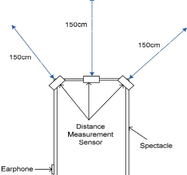
Figure 2 shows the configuration of the system in order to generate the vibration and sound warning syst em from the vibrator and the earphone. In SMART EYE system, the vibrator and earphone was chosen to give warn to the user once the obstacles was detected. From Fig. 2, the system of SMART EYE consists of obstacles detection by using distance measurement as an
input from four pieces of ultrasonic sensor which are used and located at the developed spectacle in order to measure the distance of obstacles front, right, left and down. The measured data from ultrasonic sensor will be transferred to PIC microcontroller. If the distance for front sensor from the obstacles is more than 150 cm, the vibrator and earphone will not be activated. Else, if the measured distance data is less or same 150 cm, the vibrator and earphone will be activated through PIC microcontroller and generate by using H-bridge motor driver by applying Pulse Width Modulation (PWM). At the same time, the power supply for SMART EYE is rechargeable battery that can be charging using DC adapter while at home and PV panel when the system run at outdoor.
Figure 2. Experimental Setup
On the other hand, the directional angle which has been designed for locating the ultrasonic sensor can be illustrated as Fig. 3. This developed SMART EYE is use d like a normal spectacle where mounted at huma n’s forehead. In order to keep the safety of user, the limitation of front sensor is determined to 150 cm. Therefore, user can stop and easily from the obstacle because the distance of user from the obstacle still have about 150 cm. In addition, the sensor for down sensor also has special functions which can be used to detect wall or hanging object. If the measured distance for down’s sensor is over than 160 cm which are 10 cm longer than set length, it means there is hanging object in front. Else, if the measured distance for down’s sensor is less than 140 cm which are 10 cm longer that set length, it means there is wall in front.
3. PROPOSED WARNING SYSTEM
3.1 Vibration and sound system
For the proposed warning system, the vibration type and sound type system is the best solution as a warning system for the visually impaired person because it applied the touch sense of human and hear sense as medium of communication between device and human when the system is run. The human’s sense of touch and hear is the very suitable sense for visually impaired person to know the circumstances around because it gives direct connection to the user. Technically, four pieces of vibrator are mounted to the gloves at different location. Each location have its own function that show distance inputs (sensor) from different direction such as front, left, right and down which can be illustrated in Fig. 4. The obstacle’s distance is inputted to the controller and gives some command to vibrator while obstacle is detected.
In addition, the sound system for warning device is use only a earphone to generate the DO, RE, MI and FA beep signal to differentiate the location of obstacle for front, down, left and right. The different sound can be generated by using the setting of frequency in the program. The beep signal also will be generated parallel with vibration method in order to ease the user to differentiate the sound. The strength of the beep also can be adjusted by adjusting the resistor. The type of vibrator which is used in the proposed warning system is flat coreless vibrator that can be illustrated in Fig. 4.
Figure 4. Flat Coreless Vibrator
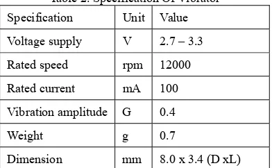
Table 2. Specification Of Vibrator
Specification Unit Value
Voltage supply V 2.7 – 3.3
Rated speed rpm 12000
Rated current mA 100
Vibration amplitude G 0.4
Weight g 0.7
Dimension mm 8.0 x 3.4 (D xL)
From the table, the value of standard voltage is 3V and the operating voltage range is 2.7V-3.3V. The speed of vibrator is controlled by Pulse Width Modulation (PWM) on PIC16F84A at controller. The vibrator is one type of DC Motor and need a motor diver to control the motor. In this system, the IC type H-bridge motor driver is used in order to drive the vibrator successfully.
3.2 Simulation
The proposed warning system uses the PIC microcontroller made by Microchip as a main controller to control the system. The integrated chip(IC) that use is PIC16F84A and all the programming made is compiling to PIC16F84A by using PIC burner. The program is simulating at microcontroller software (MikroC) and the Proteus 7 software is chosen to simulate the program. First at all, the program is made to give a pulse “on” and “off” of the motor without receive data from input. Then the program will test based on the simulation at Proteus 7 software.
Figure 5. Schematic diagram by using Proteus
After the simulation phase, the second step is proceeding by using real time distance measurement signal as input.. The vibrator is set at different value of Pulse Width Modulation (PWM) to give a different speed at different distance. The strength of the beep also set to be low or high depend to the distance. Next, the real programming that receives an input from distance measurement is build after the design of prototype is done. The programming is needed to merge with the distance measurement from the other parts to get the input data. Figure 5 shows the schematic diagram which are designed to evaluate the validity of the proposed experimental setup.
4. EXPERIMENTAL RESULT
In order to evaluate the effectiveness the proposed warning system which has been developed in SMART EYE device, the simulation program by using Proteus is designed. From the figure, the PIC16F84A as a PIC controller and four pieces of DC motor as vibrator are used in the designed spectacle. Before start the simulation, the programming is compiled to the MikroC at first. Then, the simulation is run. As the consequences, the result shows the warning signals are generated by vibrator and earphone synchronously after detecting the obstacle. The vibrator is activated while detecting the obstacle at front, right, and left and down.
device to give fast responses; long time performance and safe to use without have a high risk of health problem. The different strength of the vibration and sound can be produced when detecting different distance to the obstacles.
The flat coreless vibrator is used in the developed SMART EYE because it has a small diameter and the operating voltage is suitable for human being. Microcontroller is use to make a complete programming and then is simulate at the Proteus. The best strength of using the vibration and sound is determined by survey and get the feedback from the user. The project is low cost project with using the cheap but effective component like vibrator and earphone because most visually impaired men belong to lower income group.
5. CONCLUSIONS
In this paper, the travel assistive device for visually impaired person is designed and developed. In addition, the simulation program has been conducted by using Proteus and the experiments on proposed warning system for the developed SMART EYE. Firstly, the designed simulation program is effectively activated when each vibrator and earphone run with synchronously. Besides, the effectiveness of this developed SMART EYE also confirmed when the vibrator at developed device are vibrated if the obstacles are detected. The vibrator is vibrated according to the direction of obstacle which has been detected.
In the future, the more advanced assistive device for visually impaired person which is using audio visual system and navigation system. In addition, more experiments and specimen will be conducted when the visually impaired person is at crowded people such as supermarket and obstacle avoidance for high speed movement such as car or ant transport.
ACKNOWLEDGMENT
This research was supported by research grant from Universiti Teknikal Malaysia Melaka award no. PJP/201 1/FKE (15A) S00833 and FRGS/2012/FKE/TK02/03/ 2/F00124 with also technically support from Yasuno laboratory member, The University of Tokushima, J apan.
REFERENCES
[1] Country Repor Malaysia, The 7th ASEAN & J apan High Level officials Meeting on Caring Societies: “Towars and inclusive society” – strengthening the collaboration between social welfare , health and medical systems for child ren with disabilities, Sept 2009
[2] Katherine Guernsey, Marco Nicoli and Alberto Nini, Convention on the Rights of Persons with Disabilities: Its Implementation and Relevance for the World Bank, SP DISCUSSION PAPER, No 0712, June 2007
[3] Pravin L.Nanayakkara, Anya R.Nanayakkara, Lak anayakkara, “System for Guiding the visually han dicapped” U.S patent 6,867,697, Mar 15, 2005 [4] S. Shoval, J. Borenstein, and Y. Koren, "Audit
ory guidance with the NavBelt - A computeriz ed travel air for the visually impaired", IEEE Trans on Systems, Man, Cybernetics, Vol. 28, No. 3, pp.459-467, 1998
[5] J. Borenstein, and I. Ulrich, "The GuideCane – A Computerized Travel Aid for the Active Guidance of Visually impaired Pedestrians.", In t Conf on Robotics and Automation, pp. 1283-1288, 1997
[6] G. Lacey, K.M. Dawson-Howe, “The Applicati on of Robotics to A Mobility Aid for The El derly Visually impaired,” Robotics and Autono mous Systems, Vol. 23, No. 4, pp.245-52, 199 8.
[7] H. Mori, S. Kotani, N. Kiyohiro, “A Robotic Travel Aid "HITOMI" ,” Proc. of the 1994 IE EE/RSJ/GI Int. Conf. on Adv. Rob. Sys. Vol. 3, pp.1716 –1723, 1994.
[8] P. Aigner, B. McCarragher, “Shared Control Fr amework Applied to a Robotic Aid for the vis ually impaired,” Proc. of 1998 IEEE Int. Conf. on Rob. and Auto, pp.717 –722, 1998. [9] Munetatsu Hara, Takashi Yasuno and Hironobu Ha
rada, “Affordance Performance of Electric Wheelc hair with Force-Feedback Joystick”, Proceedings o f International Symposium on Biological and Ph ysiological Engineering / 22nd SICE Symposium on Biological and Physiological Engineering, No. 2C3-4, pp.241-244, January 13-14, 2008, Harbin, China
[10] R. H. Byrne, “Global Positioning System Rece iver Evaluation Results", Sandia Report SAND 93 0827, Sandia National Laboratories, Albuqu erque, NM, Sep.,1993
[11] F. Tsuzuki and K. Sasaki, "Novel Configuratio n of Ultrasonic Sensor for Mobile Robot", IE EE RSJ Int. Conf. on Intelligent Robots and S ystems, pp.2080-2085, Sep. 12-16, 1994. [12] A.M. Kassim, M. H. Jamaluddin, M. R. Yaaco