DESIGN AND DEVELOPMENT OF LOCKING DEVICE FOR PROTON WAJA GLOVE BOX
JAMARIZAN BIN MOHD ISA
‘I / we admit that have read this work and in my / we opinion this work satisfied the scope and quality aspect for the
Bachelor of Mechanical Engineering (Automotive) awarded’
Signature :………
Supervisor Name 1 : Mohd Zakaria B. Mohammad Nasir
ii
DECLARATION
“I admit this report is my own work except for the summary and passage which each of it already been explained it source”
Signature :
iii
DEDICATION
Thanks to ALLAH S.W.T because with His blessings, I manage to finish this report according to the dateline. I dedicate this report to my beloved family who has always
iv
ACKNOWLEDGEMENT
Alhamdulillah thanks to God for giving me the opportunity in order to complete my Project Saujana Muda (PSM). I would like to express my gratefully for the entire person that involves in completely my final project.
For the first, I am grateful to my project’s supervisor En Mohd Zakaria B. Mohammad Nasir for his support and guidance me to complete the project. Any suggestion, ideas, any opinions from and what ever came from him are the learning process for me as a student. To the technician who spend a lot of time to help me to finish my project.
To my parent, thank you so much for their moral support and advice for their son in completing this final project. A lot of time and money were used in this project and they were my financial source.
v
ABSTRAK
vi
ABSTRACT
viii 2.5.1 Electronic Data Required for RP 15
2.5.2 Solid Modeling 16
2.5.3 Surface Modeling 16
2.5.4 Standard Triangulation Language (STL) 16 2.5.5 Fused Deposition Modeling (FDM) 17 2.5.6 Advantage by using Rapid Prototyping 18
2.6 Latch Material 19
2.6.1 Poisson’s Ratio 20
2.7 Torsion Springs 21
ix
3.4 Experiment 1: Determine Force to Retract Chock 27
3.5 Torsion on spring 28
3.6 Actual Force Value on Latch to Retract Chock 29 3.7 Maximum Force Value on Latch Cause Failure 30
3.8 MSC Nastran Patran 32
3.8.1 Flow Process Analysis 32
3.8.2 Import Geometry 33
3.8.3 Meshing 34
3.8.4 Material Properties 34
3.8.5 Boundary Condition and Force 35
3.9 Proton Waja’s Glove Box Locking Device Mechanism 36
3.9.1 Propose Design 37
3.9.2 Screening Process 38
3.10 Rapid Prototyping 39
3.10.1 Step to Run Machine Rapid Prototyping (RP) 39
3.10.2 Flow Process 40
x
CHAPTER IV RESULT AND DISCUSSIONS
4.1 Introduction 41
4.2 Analysis Result According to Actual Force 42 4.3 Analysis Result According to Maximum Force 43
4.4 Design and Modification 44
4.4.1 Modification of Thickness 44
4.5 Stress Analysis of Different Thickness 46 4.6 Analysis for Different Materials (polycarbonate and 47
Polystyrene)
4.7 The Best Locking Device Mechanism 48
4.7.1 Print Using Rapid Prototyping 48
CHAPTER V CONCLUSIONS AND RECOMENDATION
5.1 Introduction 49
5.2 Conclusions 50
5.3 Recommendation for future work 51
REFERENCE 52
APPENDIX 54
xii
Figure 3.10: Free-body Diagram of Maximum Force 31
Figure 3.11: The Geometrical Modeling of the Glove Box Latch 33 Figure 3.12: The Geometrical Modeling of the Glove Box Latch 34 Figure 3.13: Boundary Condition and Force Apply at the Latch 35
Figure 3.14: The Current Mechanism Design 36
Figure 3.15: Concept A 37
Figure 3.16: Concept B 37
Figure 3.17: Concept C 37
Figure 3.18: Schematic Diagram of Rapid Prototyping Process 40 Figure 4.1: Von Misses Stress Contour for 3D Analysis for Actual Force 42 Figure 4.2: Von Misses Stress Contour for 3D Analysis for Maximum Force 43 Figure 4.3: Failure Areas that are Frequently Occur on the Proton Waja’s Glove 44
Box Locking Device
Figure 4.4: Stress vs. Modification Area 45
Figure 4.5: Stress distribution of the Proton Waja’s glove box latch 46 Figure 4.6: Stress Distribution of Thickness Modification 46 Figure 4.7: Finite Element Analysis for Different Materials 47 Figure 4.8: A New Concept Design of Locking Device Mechanism 48
xiii
LIST OF TABLE
TABLE PAGE
Table 1: Material Properties 20 Table 2: Spring wire modulus of elasticity in shear (G) and tension (E). 22
Table 3: Actual force 27
Table 4: Selection 38
xiv
LIST OF APPENDIX
NO TITLE PAGES
A Polystyrene – Unfilled 54 B Polystyrene Mechanic Properties 55
C Typical Yield strength 56
1
CHAPTER I
INTRODUCTION
1.1 Background
This project is to perform an improvement a locking devices for Proton Waja glove box process in order to determine the design and development of a locking devices for Proton Waja’s glove box, besides that this project aims to find a solution to improve the quality of the locking device and make a little modification for locking device so can function with much finer. The current model was measured using Vernier Calipers and ruler (manual handling) .After all part dimension have been measured by the tools.
2 The new model will be redrawn in CATIA with new modification. The new model will be analyzed by using finite element to ensure those model will not failure for the second time testing. The improvement based on analysis and design characteristic will be done. After all process the product would be produced by using rapid prototyping machine. The rapid prototyping model also can used to get an accurate result from analysis as the raw material is the same material used in production.
1.2 Objective
An improvement a locking device for Proton Waja’s glove box.
1.3 Scope
Measure coordinates via measurement tools CMM/3D scanner, Vernier calipers and ruler.
Design and modeling locking device system in CATIA/Solidwork. Perform an analytical study on critical component by using MSC
Nastran Patran.
New improvement based on analysis and design characteristic (dimension or material).
Print as prototype model by using rapid prototyping machine (RP).
3 1.4 Problem Statement
Complaint from customers Proton Waja’s, they have difficult to open the glove box because it always stuck especially at the right side chock.
Some time the lever at the handle glove box was break because of the over force that imposed to the latch.
Material used are not suitable to used, may be need replace to the another material are more strong.
4 1.5 Gantt Chart
PSM 1
5 Finate Element Analysis ( MSC Nastran Patran)
New Design
Model (Catia)
Finate Element Analysis ( MSC Nastran Patran)
Discussion: Comparison –Material / Design -Finate Element Analysis
Rapid Prototyping (RP)
PSM 1
6
CHAPTER II
LITERATURE REVIEW
2.1 Introduction
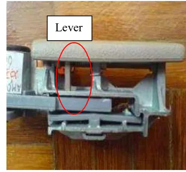
7 2.2 Failure Part of Proton Waja’s Latch
Figure 2.1: Latch failure
The red circle shows the failure part. Figure 2.1 shows the lever was received maximum force from the hand. The spring does not support the latch to absorb the force to minimize the force value and avoid the latch from brake. Actually the function of spring is to ensure that the latch back to its position or retract.
8 2.3 Finite Element Analysis (FEA)
Finite element analysis (FEA) is a computerized method for predicting how a part or assembly will react to environmental factors such as force, vibration and heat. Though it is called "analysis," in the product design cycle, it is used as a virtual prototyping tool to predict what is going to happen when the product is used.
Finite element analysis, as related to the mechanics of solids, is the solution of a finite set of algebraic matrix equations that approximate the relationships between load and deflection in static analysis and velocity, acceleration, and time in dynamic analysis.
In 1678, Robert Hooke set down the basis for modern finite element stress analysis as Hooke's Law. Stated simply, an elastic body stretches (strain) in proportion to the force (stress) on it. There are only one equation needs to understand linear finite element stress analysis and mathematically, the formula is as follow:
kx
F
---(1)Where: F = force
k = proportional constant x = distance of stretching
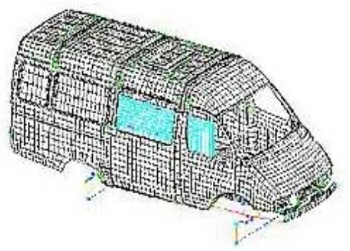
The finite element method works by breaking a real object down into a large number of elements (1000s or 100,000s of cubes) or meshing such as Figure 2.2. The behavior of each little element, which is regular in shape, is readily predicted by a set of mathematical equations. The summation of the behavior of each individual element produces the expected behavior of the actual object.
9 The word "finite element analysis" indicates that there are a finite number of elements in a model, such as Figure 2.2. Prior to the development of FEA tools, engineers employed integral and differential calculus techniques to solve engineering analysis problems. These techniques break down objects into an infinite number of elements for problem solving.