THE DESIGN AND DEVELOPMENT OF WARNING DEVICE FOR LOW PRESSURE LPG TANK
FADHLIZIL FARIZ BIN MD SAAD
(Thermal-Fluid)’
Signature :………
Supervisor : Mr. Suhaimi Bin Misha
THE DESIGN AND DEVELOPMENT OF WARNING DEVICE FOR LOW PRESSURE LPG TANK
FADHLIZIL FARIZ BIN MD SAAD
This dissertation is submitted as partial fulfillment of the requirement for the degree of Bachelor of Mechanical Engineering (Thermal Fluid)
Faculty of Mechanical Engineering Universiti Teknikal Malaysia Melaka
” I declare that this report is done by my own exclude the citation with the mentioned references for each”
Signature :……….
Author Name :……….
iii
For my lovely parent
Encik Md. Saad Bin Ahmad dan Puan Manisah Binti Hussien
My brothers
Fadhlizil Fashriq Bin Md. Saad Fadhlizil Faiq Bin Md. Saad
ACKNOWLEDGEMENTS
Alhamdulillah, praise to Allah s.w.t. the most gracious, the most merciful. Thank you for giving me the strength and spirit for me to complete this research on the design and development of warning device for low pressure LPG tank. I would have never completed this academic exercise if not for the help by some people.
Throughout 13 weeks in completion this project, I am very grateful with the co-operation from lecturer, technicians and friends. I have learned so many things such as instrumentation, job skills, interaction between individuals and the most precious is how to produce a technical report. My highly appreciation to Mr. Suhaimi Misha who supervised my progress for this technical report writing, for shared her knowledge and concerned towards my project. Without his guidance, assistance, encouragement and patience, I don’t think I can manage to complete this project on time. Thank you so much sir.
v
ABSTRACT
ABSTRAK
vii
TABLE OF CONTENT
CHAPTER TITLE PAGE NUMBER
DECLARATION ii
DEDICATION iii
ACKNOWLEDGEMENT iv
ABSTRAK v
ABSTRACT vi
TABLE OF CONTENT vii
LIST OF TABLE x
LIST OF FIGURE xi
LIST OF SYMBOL xiii
LIST OF APPENDICES xiv
CHAPTER 1 INTRODUCTION
1.1 Project Background 1
1.2 Problem Statement 2
1.3 Project Advantages 2
1.4 Objectives 3
1.5 Scope 3
CHAPTER 2 LITERATURE REVIEW
CHAPTER TITLE PAGE NUMBER
2.1.1 LPG Tank Advantage 5
2.1.2 The properties of LPG gas 6
2.1.3 Butane and Propane 8
2.2 Ideal Gas Law 10
2.3 Vapourisation 10
2.4 Pressure switch 13
2.4.1 Examples of pressure switch 14 2.4.2 Types of Pressure Switches 15
CHAPTER 3 METHODOLOGY
3.1 Chart 16
3.2 Project Flow Chart 17
3.3 Experiment I 20
3.3.1 Procedures 20
3.4 Experiment II 22
3.4.1 Procedures 22
3.5 Experiment III 24
3.5.1 Procedures 24
3.6 Design 25
3.6.1 Apparatus 25
3.7 Experiment IV 30
3.7.1 Procedures 31
CHAPTER 4 RESULT
4.1 Experimental I Data 32
4.2 Experimental I Result 33
4.3 Experiment II Result 35
4.4 Experiment III Result 35
ix
CHAPTER TITLE PAGE NUMBER
4.6 Experiment IV Result 37
CHAPTER 5 DISCUSSION
5.1 Graph for Experiment I 38
5.2 Differential of Common Regulator 40 and Adjustable Regulator
5.3 The Suitable Pressure for Cooking 41
5.4 Complete Fabrication Process 42
5.5 The Duration of LPG Tank Pressure 42 to Decrease From 0.1 bar to 0 bar
CHAPTER 6 CONCLUSION 43
RECOMMENDATION 44
REFERENCES 45
LIST OF TABLE
NO. TITLE PAGE NUMBER
2.1 Typical Properties of LPG 7
2.2 LPG Tank Properties 8
2.3 The physical properties of propane and 9
butane gases
3.1 Specification of pressure switch 26
3.2 Pressure switch details 26
4.1 Experimental 1 data 32
4.2 Theoretical result 34
4.3 Result from experiment II 35
4.4 Result from Experiment III 35
4.5 Duration of LPG tank pressure to decrease 37
from 0.1 bar to 0 bar
5.1 Comparison between common regulator and 40
xi
LIST OF FIGURE
NO. TITLE PAGE NUMBER
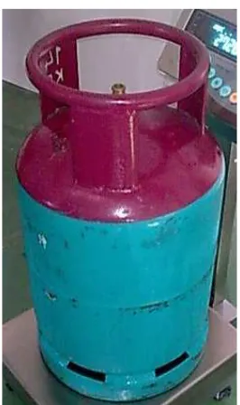
2.1 LPG tank for cooking 4
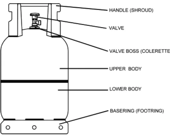
2.2 Structure of LPG tank model 5
2.3 Prover at the start 12
2.4 Prover at the end 12
2.5 Examples of pressure switch 14
3.1 Flow Chart for PSM I 18
3.2 Flow Chart for PSM II 19
3.3 Experiment apparatus 20
3.4 LPG tank on the weighing scale 21
3.5 Taking pressure in LPG tank 21
3.6 Blow the gas 21
3.7 LPG Hose with Adjustable Regulator 22
3.8 Placed the Adjustable Regulator 23
3.9 LPG Hose Connect to Pressure Gauge 23
with Pneumatic Tube
3.10 Measure Pressure 23
3.11 Turns of Adjustable Regulator 24
3.12 Pneumatic Circuit 28
3.13 Complete circuit of pressure switch 28
3.14 Battery 29
NO. TITLE PAGE NUMBER
3.16 Switch 30
3.17 Measure pressure in LPG tank 31
3.18 Both stoves is switch on 31
4.1 Complete Device 36
4.2 Complete Fabrication 36
5.1 Graph usage of gas versus mass of gas 39
xiii
LIST OF SYMBOL
LPG Liquefied Petroleum Gas
m molar mass
P Absolute pressure
R universal gas constant (J.kg-/K) T Absolute temperature
V Volume
V Volts
LIST OF APPENDICES
NO. TITLE PAGE NUMBER
1 Stove and LPG Tank 46
2 Pressure Gauge 46
3 Weighing Scale 47
4 Stopwatch 47
5 Connector 48
6 Hose 48
7 Pressure Gauge 49
8 Tee Joint 49
9 Pneumatic Tube 50
10 Pressure Connector 50
11 Common Regulator 51
12 LPG Hose Clip 51
13 Adjustable Regulator 52
14 The Device 52
15 The Device Location 53
16 The Complete Fabrication 53
17 Specification of Pressure Switch 54
18 Gant Chart for PSM I 57
1
CHAPTER 1
INTRODUCTION
1.1 Project Background
LPG (Liquefied Petroleum Gas) has been formed over millions of years beneath the ground. Gas rigs produce the gases as a mixture, where they are separated into methane, the LPG's of propane and butane and other gases. LPG is also produced from crude oil at refineries by distillation process.
LPG exists as a gas at normal atmospheric pressure, only existing in a liquid form at very low temperatures, or under pressure. Normally, the gas is stored in liquid form under pressure in a steel container. When the pressure is released (e.g. when the gas supply valve is turned on), the liquid will boil and form a vapour. It's this vapour (gas) that is used to fuel appliances.
Pressure increases with temperature, so if the temperature around the tank increases, so will the pressure inside the tank as the liquid expands. Tanks are normally fitted with a pressure relief valve to release any extreme build up of pressure safely.
Now day, LPG is used as a fuel for domestic (cooking) but people is only aware the LPG tank is empty when it can not produce gas to cook. That way, this project suggests the device that can give early warning to the user when the LPG tank is almost empty so that users are ready to change the tank.
1.2 Problem Statement
People are only aware the LPG tank is empty when it can not produce gas to cook. This situation will give problem to the user to change the LPG tank with the new one. It is better if there is early warning to the user when the LPG tank is almost empty so that users are ready to change the tank.
1.3 Project advantages
3
1.4 Objectives
Objective for this project are:
1. To design and fabricate device that can produce sound if the LPG tank pressure drop at certain level.
2. To investigate the pressure of LPG tank and identify the minimum pressure required to active the warning device.
1.5 Scope
CHAPTER 2
LITERATURE REVIEW
2.1 LPG Tank
[image:20.612.261.394.468.692.2]LPG is used as a fuel for domestic (cooking), industrial, horticultural, agricultural, heating and drying processes. LPG can be used as an automotive fuel or as a propellant for aerosols, in addition to other specialist applications. LPG can also be used to provide lighting through the use of pressure lanterns.
5
Figure 2.2: Structure of LPG tank model
(Source: Journal comparison of bursting pressure results of LPG tank using experimental and finite element method by Egemen Aksoley, Babur Ozcelik and Ismail Bican, 2007)
2.1.1 LPG Tank Advantage
The advantages of LPG are:
Its relatively less components, it is easy to achieve the correct fuel to air mix ratio that allows the complete combustion of the product. This gives LPG its clean burning characteristics.
LPG is a good substitute for petrol in spark ignition engines. Its clean burning properties, in a properly tuned engine, give reduced exhaust emissions, extended lubricant and spark plug life.
As a replacement for aerosol propellants and refrigerants, LPG provides alternatives to fluorocarbons, which are known to cause corrosion of the earth's ozone layer.
2.1.2 The properties of LPG gas
7
Table 2.1: Typical Properties of LPG
(Source: Journal comparison of bursting pressure results of LPG tank using experimental and finite element method by Egemen Aksoley, Babur Ozcelik and Ismail Bican, 2007)
Typical Properties of LPG
Hydrocarbon Composition (by
Volume)
Commercial Propane (C3H8) % 30 Commercial Butane (C4H10) % 70 Vapour Pressure at ambient kPa 500 Total Sulphur (stenched) mg/kg < 75 Free Water (Visual Inspection) None Relative density (compared to dry air) 1.85
Copper Corrosion Strip 1
Calorific Value, gross MJ/kg Btu/lb
49.5 21,300 Calorific Value, nett MJ/kg
Table 2.2: LPG Tank Properties
(Source: Journal comparison of bursting pressure results of LPG tank using experimental and finite element method by Egemen Aksoley, Babur Ozcelik and Ismail Bican, 2007)
Property Units Commercial
Propane
Commercial
Butane Mixture 50% each
Specific gravity of Liquid at 15 deg C (Water=1)
0.504 0.582 0.543
Specific gravity of Vapor at 15 deg C(Air=1)
1.5 2.01 1.75
Vapor pressure at 38 deg C
Kg/sq.cm
13.8 2.6 8.0
Boiling point at atm pressure
Deg C
- 42 9 + 9 to - 42
Ignition temperature in air
Deg C
495-605 480-535 480-605
Latent Heat of Vaporization
Btu/lb
184 167 175
2.1.3 Butane and Propane