UNIVERSITI TEKNIKAL MALAYSIA MELAKA
Design and Development of Automated
“Press Device” f
or Emerged Stamp
Thesis submitted in accordance with the partial requirements of the Universiti Teknikal Malaysia Melaka for the
Bachelor of Manufacturing Engineering (Manufacturing Design) with Honours
By
Mohd Khairulnizam Bin Mhd Nasir
Faculty of Manufacturing Engineering
UTeM Library (Pind.1/2007)
UNIVERSITI TEKNIKAL MALAYSIA MELAKA
BORANG PENGESAHAN STATUS LAPORAN PSM
JUDUL:
“Design and Development of Automated Press Device for Emerged Stamp”
SESI PENGAJIAN: Semester 2 2007/2008
Saya Mohd Khairulnizam Bin Mhd Nasir
mengaku membenarkan laporan PSM / tesis (Sarjana/Doktor Falsafah) ini disimpan di Perpustakaan Universiti Teknikal Malaysia Melaka (UTeM) dengan syarat-syarat kegunaan seperti berikut:
1. Laporan PSM / tesis adalah hak milik Universiti Teknikal Malaysia Melaka dan penulis.
2. Perpustakaan Universiti Teknikal Malaysia Melaka dibenarkan membuat salinan untuk tujuan pengajian sahaja dengan izin penulis.
3. Perpustakaan dibenarkan membuat salinan laporan PSM / tesis ini sebagai bahan pertukaran antara institusi pengajian tinggi.
4. *Sila tandakan (√)
SULIT
TERHAD
√ TIDAK TERHAD
(Mengandungi maklumat yang berdarjah keselamatan atau kepentingan Malaysia yang termaktub di dalam AKTA RAHSIA RASMI 1972)
(Mengandungi maklumat TERHAD yang telah ditentukan oleh organisasi/badan di mana penyelidikan dijalankan)
(TANDATANGAN PENULIS)
Alamat Tetap:
NO A21, LORONG DAHLIA 2/1, TAMAN DAHLIA INDAH,
DECLARATION
I hereby, declared this thesis entitled “design and development of automated press device for emerged stamp” is the results of my own research
except as cited in references.
Signature : ……….
Author’s Name : Mohd Khairulnizam Bin Mhd Nasir
APPROVAL
This PSM submitted to the senate of UTeM and has been as partial fulfillment of the requirements for the degree of Bachelor of Manufacturing Engineering (Design Manufacturing) with Honours. The members of the supervisory committee are as follow:
………
i
ABSTRACT
ii
ABSTRAK
iii
DEDICATION
iv
ACKNOWLEDGEMENTS
v
List of Abbreviations, Symbols, Specialized Nomenclature...xiii
List of Appendices...xiv
1. INTRODUCTION...1
1.1.Background...1
1.2.Problem Statement...2
1.3.Project Objectives...2
1.4.Scope of Works...3
1.5.Project Process Flow...3
1.6.Report structure...5
2. LITERATURE REVIEW...7
2.1. Definition...7
2.2. Hand embosser (Manual)...8
2.2.1. Hand Embosser Image...8
2.2.2. Hand Embosser Specification and Component...9
2.2.3. Embosser Instructions...9
vi
2.3. Electric Embosser (SemiAutomatic)...13
2.3.1. JES Electric Embosser...14
2.3.2. Widmer E-3...15
2.4.Machine Embosser (Automatic)...16
2.4.1. Product image of Embosser 4Waves PRO Machine...16
2.4.2. Terminology………....17
2.4.3. Product Overview...18
2.4.3.1. Operating System...18
2.4.3.2. Features...18
2.4.4. Setting Up the Embosser...19
2.4.4.1. Voltage 230V and 115V...19
2.4.4.2. Unlocking the Embosser Head...19
2.4.5. Power on Embosser...20
2.4.6. Paper Handling...20
2.4.6.1. Default Paper Setting...20
2.4.7. Paper Length and Width...21
2.4.8. Load Paper...21
2.4.8.1. Load Paper in All Modules………..21
2.4.8.2. Sequence for Paper Loading...22
2.4.8.3. Change a Paper Width...25
2.4.8.4. Paper jam during “Load Paper”...25
2.4.9. Paper Out...25
2.4.9.1. Tear off Paper Position...25
2.4.9.2. Remove Paper...26
2.4.9.3. Paper out of Chains...26
2.4.9.4. Out of Paper – Embossing the Remaining Part…………...27
2.4.9.5. Paper Folding Direction...27
2.4.9.6. Paper Service –Paper Out of Bin………....27
2.4.9.7. Clean Paper Jam...28
2.4.10.Replacing Embossing Module 4Waves PRO ...28
2.4.10.1. Replace with Service Embossing Module ...28
vii
2.5.Design Consideration ...32
2.5.1. Benchmarking Design ...34
2.6. Aluminium Properties ...35
2.7. Survey Description ………..36
3. METHODOLOGY ...37
3.1.Definition ...37
3.2.Components/parts Selection ...39
3.3.Material Selection ...47
3.4.Product Tree Structure...49
3.5.Machine and Process Requirement...50
3.5.1. Machine used...50
3.5.1.1. Milling Machine ...50
3.5.1.2. Drilling Machine...52
3.5.1.3. Lathe Machine...52
3.5.1.4. Bend Saw Machine...53
3.5.2. Process Related...54
3.5.2.1. Process 1 (Cut the Raw Material of Aluminium Plate) ...54
3.5.2.2. Process 2 (Cut the Material Based on Specification)...55
3.5.2.3. Process 3 (Drilling and Counter bore Required)...56
3.5.2.4. Process 4 (Cut the Raw Material of Aluminium Rod)...58
3.5.2.5. Process 5 (Facing and Turning Process Required)...59
3.5.2.6. Process 6 (Assembly to Final Product)...60
3.5.3. Isometric View of Final Product...62
3.6.System Operating...63
3.6.1 Automatic Mode...63
3.6.2 Manual Mode...63
3.7.Electric Circuit...66
viii
4. RESULT AND ANALYSIS...68
4.1 Result...68
4.2 Analysis...70
4.2.1 Working Equipment...71
4.2.2 Working Procedure...72
4.2.3 Open Environment...74
4.2.3.1 Sound Level Data for Fabrication Lab...75
4.2.3.2 Graph of Sound Level at Open Environment………..79
4.2.4 Close Environment ...80
4.2.4.1 Sound Level Data for Metrology Lab ...80
4.2.4.2 Graph of Sound Level at Close Environment...84
5. DISCUSSION...85
5.1 Discussion...85
6. CONCLUSION AND RECOMMENDATION...87
6.1 Conclusion...87
6.2 Recommendation...88
REFERENCES...90
APPENDICES
ix
2.6 Making Impressions 11
2.7 Text only 12
2.8 Simple graphic 12
2.9 Contoured design 13
2.10 JES electric embosser 14
2.11 Widmer E-3 electric embosser 15
2.12 Embosser 4Waves PRO Machine 16
2.13 Transport lock 19
2.14 Removing the transport lock 20
2.15 Design machine for paper loading 21
2.16 Step 1 (Place the paper into its position) 22
2.17 Step 2 (Find the started point of paper) 22
2.18 Step 3 (Inside the paper into a module #4) 23
2.19 Step 4 (Make sure the paper correctly inside) 23
2.20 Step 5 (Manually continue inside paper to module #3, module #2, and module #1)
23 2.21 Step 6 (Paper complete install to a module #4, #3, #2, #1) 24
x
2.23 Papers tear off 26
2.24 Chain length and position 27
2.25 Turn off the power 28
2.26 Lift the selected embosser module 29
2.27 Lift the replacement module and place it in the empty position 29
2.28 Turn on the power and wait for feedback 30
2.29 DFM Flow Chart 33
2.30 Design 1 34
2.31 Design 2 34
2.32 Design 3 35
3.1 Methodology flow chart 38
3.2 Product tree structure 49
3.3 Vertical spindle column 51
3.4 Horizontal spindle column 51
3.5 Drilling machine 52
3.6 Lathe machine 53
3.7 Band saw cutting machine 54
3.8 Raw material for top and base structure 55
3.9 Top and base structure after cutting process 56
3.10 Making hole and counter bore 57
3.11 Raw material for aluminium rod 58
3.12 Aluminium rod of facing and turning process 60
3.13 Final design of automated “press device” of Emerged Stamp 61
3.14 Top and side view of final design 61
3.15 Isometric view of final design 62
3.16 System operating flow 65
3.17 Electric diagram 66
3.18 Pneumatic diagram 67
4.1 Run in automatic mode 68
xi
4.3 Run test for “press device” 69
4.4 Cylinder extent 70
4.5 Sound level meter 71
4.6 Measuring tape 71
4.7 Preparation of the equipment 72
4.8 Compressor unit 73
4.9 Turn on the automated “press device” 73
4.10 Start taking data of the sound level 74
4.11 Fabrication Lab 75
4.12 Graph different distance at Fabrication Lab 79
4.13 Metrology Lab 80
xii
LIST OF TABLES
2.1 Specification for JEC electric embosser 15
2.2 Specification for Widmer E-3 16
2.3 Terminology 17
2.4 Windows support 18
2.5 Paper setting 20
2.6 Embossing module combinations 31
3.1 Project component 39
3.2 Material selection 47
4.1 1 feet distance from air compressor at Fabrication Lab 76 4.2 5 feet distance from air compressor at Fabrication Lab 77 4.3 10 feet distance from air compressor at Fabrication Lab 78 4.4 1 feet distance from air compressor at Metrology Lab 81 4.5 5 feet distance from air compressor at Metrology Lab 82 4.6 10 feet distance from air compressor at Metrology Lab 83
xiii
LIST OF ABBREVIATIONS, SYMBOLS, SPECIALIZED
NOMENCLATURE
UTeM - Universiti Teknikal Malaysia Melaka
V - Volt
DFM - Design for Manufacturing
DFMA - Design for Manufacturing Assembly
Al - Aluminium
OSHA - Organizational Safety and Health Administration
dB - Decibel
CR1 - Coil Relay 1
T1 - Timer 1
CTR - Counter
PB - Push Button
A/M SW - Automatic/Manual Switch
MTR - Motor
xiv
LIST OF APPENDICES
1
CHAPTER 1
INTRODUCTION
1.1 Background
Emerged stamp is one of the important things use for the purpose of stamping a piece of an examination slip. The project is actually based on problem existing at school when they have to put an emerged stamp on an examination slips. It is actually reliable using hand (manually handling) if there only one piece of paper need to be stamp. But it will have a problem when a thousand of examination slips need to be stamped. The limitation of using manually handling when it comes to something that human can’t do for a short time to complete stamping. The main thing is to complete stamping a thousand of examination slips in a short while without using human energy especially when it can be done automatically.
2
The automated “press device” for emerged stamp is actually build up or develop towards its application and it will be able to work fast and efficient during the less monitoring on its operation. That why it is very useful to have this kind of automated “press device” of emerged stamp in the school, polytechnic, university and other institution. So, for the development it needs a lot of research on the part that use for the automated “press device” for emerged stamp and the design must be consider to place at the limited space. For the future planning of this product of emerged stamp it has to consider a several things like cost, design and material in term of to develop a product that can go through the worldwide market.
1.2 Problem Statement
The problem statements regarding this project are:
1. The manually handling (using hand) while it come to press the emerged stamp to a thousand of examination slips.
2. It needs a lot of time to finish the work of emerged stamp when it comes with other work to do especially for those who work as a clerk.
3. The most difficult things while operating a manual emerged stamp is on the adjustment of the examination slip to it proper position.
4. For the reason of reducing a human energy it is one of the major factor that the
automated “press device” of emerged stamp is developed.
1.3 Project Objectives
3
1. To survey on press mechanism of emerged stamp whether it is reliable to use in school, polytechnic or other institution.
2. To design a better product of emerged stamp based on the application and functionality of the product.
3. To upgrade the recent product which is used an electric power and manually hand as a device to emboss the examination slip. The upgraded system in this project will use pneumatic system as a press device.
1.4 Scope of Work
There are five main areas that have been identified:
1. Literature review to find out the various practical ways of design a better
automated “press device” of emerged stamp.
2. Study of part or component needed for developing the design. 3. Sourcing for suitable circuit and practical circuit for the project.
4. To develop a real automated “press device” of emerged stamp which is can be operated base on its purpose.
5. Finally to conduct and verify the functionality of the end product.
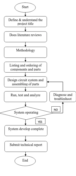
1.5 Project Process Flow
4
Figure 1.1: Process Flow Chart. Start
Define & understand the project title
Does literature reviews
Run, test and analyze Diagnose and troubleshoot Design circuit system and
assembling of parts Listing and ordering of
components and parts Methodology
System develop complete
Submit technical report System operating
End
NO
5
1.6 Report Structure
Overall, this report is divided into seven chapters. Below is the summary of each chapter within this report:
CHAPTER 1: INTRODUCTION
This chapter will include the background of the PSM project, objective of the project which need to be achieved at the end of this project, problem statement of the project, all the necessary scope of work regarding the project and methodology of the project which is put in practice throughout this project are outlined.
CHAPTER 2: LITERATURE REVIEW
This chapter will review the past of the development project or product which is has same objectives of its build. For journals, it is advisable to refer the last five years after it published. Also at the end of this chapter should include with a hypothesis (if applicable) and objectives of the study.
CHAPTER 3: MATERIALS AND METHODS/METHODOLOGY
This chapter will present the relevant descriptive, theoretical and analytical techniques used in research should be outlined. This will include material and method and also with an electrical circuit used for development project and also must be able to repeat by another researcher.
CHAPTER 4: RESULTS AND ANALYSIS
6
CHAPTER 5: DISCUSSION
This provides a general discussion on the result of study automated “press
device” of emerged stamp, stressing the significance and implications of the
findings of the research project.
CHAPTER 6: CONCLUSION AND RECOMMENDATION