i
DESIGN AND DEVELOPMENT OF TIRE FORCE MEASURING DEVICE
GOH CHEP KIEN
A project report submitted in partial fulfillment of the requirements for the award of the Degree of Bachelor Mechanical Engineering (Automotif)
Faculty of Mechanical Engineering Universiti Teknikal Malaysia Melaka
ii
“I hereby declared that this thesis is my own work except the ideas and summaries which I have clarified their sources”
Signature: ……… Author : ……… Date : ………
iii
iv
ACKNOWLEDGEMENTS
I would like to express my deepest gratitude to my supervisor, Ir. Mochamad Safarudin in my Universiti Teknikal Malaysia Melaka (UTeM) for suggesting this project and providing guidance throughout the course of this Project Sarjan Muda 1 (PSM 1). He has given me considerable freedom and shown patience as I pursed the idea development in PSM 1. Thanks again to him for reviewed the entire manuscript of this project and provided me with valuable feedback. Ir. Mochamad Safarudin also gave me a lot of good advices and best encouragement for me to complete the final year project. Moreover, he also had shared his golden time and experiences to guide me in the research.
I would like especially grateful to my FKM master student, Abang Ubaidillah and Abang Fitrian who gave me the guidance in the process of design. They had given a great idea and share their experiences to solve the problem of designing. Furthermore, they also advise me where to buy the equipments needed for developing tire force measurement platform.
In additional, I would like to express my sincere thanks to my project partner, Mr. Lee Tze Jian who continue the following part of my project to complete the whole project. Nevertheless, thanks to UTeM provided the infrastructures such as library and cyber cafe which helped in finding related journals, novels, and revision books.
v
ABSTRACT
vi
ABSTRAK
vii
TABLE OF CONTENTS
CHAPTER CONTENTS PAGE
DECLARATION ii
DEDICATION iii
ACKNOWLEDGEMENTS iv
ABSTRACT v
ABSTRAK vi
TABLE OF CONTENTS vii
LIST OF TABLES xi
LIST OF FIGURES xii
LIST OF APPENDICES xv
CHAPTER 1 INTRODUCTION
1.1 Wheel Dynamics Test Rig 1.2 Background
1.3 Problem Statement 1.4 Objective
1.5 Scopes
1.6 Significance of Study
1 1 2 4 5 5 6
CHAPTER 2 LITERATURE REVIEW
2.1 Design and Fabrication of the Six
Component Tire Force Measuring Device 2.2 Design Process on Tire Force Measuring Device
2.3 Review on Design Drawing 2.4 FEM Analysis and Optimization
7 7
9
viii
2.5 Principle of Strain Gage
2.5.1 Types of Strain Gauges 2.5.2 Structure of Foil Strain Gauge 2.5.3 Review on Strain Gage 2.6 Conclusion on Literature Review
18 19 19 20 23
CHAPTER 3 METHODOLOGY
3.1 Project Progress Flow Chart 3.2 Introduction of Force Sensor 3.3 Using on CATIA V5
3.4 Design Process
3.4.1 Design Sketches or Free-Hand Drawings
3.4.2 Design Drawing of Tire Force Measurement Device
3.4.3 Design Concept and Criteria 3.4.4 Evaluation on Design Drawing 3.5 Finite Element Method Using MSC Patran and Nastran
3.6 Procedures
3.6.1 Selection and Location Attachment of Strain Gauges 3.6.2 MSC Patran and Nastran Analysis’ Steps
3.6.3 Calibration 3.7 Conclusion
ix
CHAPTER 4 RESULT AND DISCUSSION 4.1 Structure Design
4.1.1 T-shaped Bar Device 4.1.2 Connector Beam
4.1.3 Steering Angle Structure
4.1.4 Platform with Suspension Holder 4.2 Shearing Stress on Steering Angle
Structure, Pin and Connector Beam 4.2.1 Steering Angle Structure’s
Shearing Stress Calculation 4.2.2 Pin’s Shearing Stress Calculation 4.2.3 Connector Beam’s Shearing Stress
Calculation
4.2.4 Hooke’s Law: Modulus of Elasticity
4.3 Structure Design Analysis 4.3.1 Analysis on X-axis Force 4.3.2 Analysis on Y-axis Force 4.3.3 Analysis on Z-axis Force
4.4 Tire Force Measuring Device Calibration Result
4.4.1 Longitudinal Force, Fx Calibration 4.4.2 Lateral Force, Fy Calibration 4.4.3 Vertical Force, Fz Calibration
4.4.4 Rolling Moment, Mx Calibration 4.4.5 Overturning Moment, Mx Calibration
4.4.6 Self-aligning Moment, Mx Calibration
4.5 Simulation MSC Patran/Nastran and Experimental Strain Comparison
x
CHAPTER 5 CONCLUSION 84
CHAPTER 6 RECOMMENDATION 87
REFERENCES 89
APPENDIX A APPENDIX B APPENDIX C APPENDIX D APPENDIX E
xi
LIST OF TABLE
TABLE NO.
TITLE PAGE
3.1 Design Drawing Evaluation 33
4.1 Table calibration of longitudinal force, 63
4.2 Table calibration of lateral force, 66
4.3 Table calibration of vertical force, 68
4.4 Table calibration of rolling moment, 71
4.5 Table calibration of overturning moment, 74
4.6 Table calibration of self aligning moment, 77 4.7 Strain result of Simulation Patran/Nastran and
Experimental
xii
LIST OF FIGURES
FIGURE NO.
TITLE PAGE
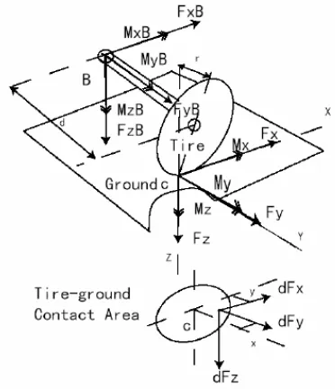
2.1 Forces and moments acting on the tire and tire measuring device
7
2.2 Measurement beam sequencing and bridge wiring. The numbering 1 to 16 is the number of strain gages which attach on the structure
11
2.3 Design of tire force sensor using CAD assembly, CATIA V5
11
2.4 Assembly drawing of novel six-axis wrist force sensor 12 2.5 Schematic diagram of the novel six-axis wrist force
sensor design which ready for attachment of strain gages on the body
13
2.6 Shoe-shape structure with two force sensors and the corresponding reference coordinate
14
2.7 Six-component force sensor in the form of 4 square-sectioned T-shape bars
14
2.8 Kinematic structure of the Stewart platform and coordinate frame assignment
15
xiii
2.14 Structure of a foil strain gauge 19
2.15 Bonding locations and numbering for the strain gages of T-shape bar
21
2.16 A full bridge composed of identical gages 22
3.1 Project Progress Flow Chart 25
3.2 French’s Model of the Design Process 27
3.3 First Design Sketch 28
3.4 Second Design Sketch 29
3.5 Third Design Sketch 29
3.6 First design drawing of tire force measurement device 30 3.7 Second design drawing of tire force measurement
device
30
3.8 Third design drawing of tire force measurement device
31
3.9 Third design drawing’s assembly 31
3.10 Hierarchical Diagram of Design Criteria 32
3.11 Strain gage selection 36
3.12 Dust and Paint Removed 36
3.13 Bonding Position Decided 37
3.14 Grease from Bonding surface is remover and cleaned 37
3.15 Adhesive Applying 38
3.16 Bond Strain Gage to Measuring Site 38
3.17 Strain Gage Pressing 39
3.18 Bonding work Completed 39
3.19 Importing Part into MSC Patran 40
3.20 Meshing on the Part 40
3.21 Static Plane and Force Applying on Part 41
3.22 Displacement Result of Part 42
3.23 Stress Result of Part 42
3.24 Fx, Fz, Mx and Mz Calibration 44
3.25 My Calibration 44
xiv
4.1 Tire Force Measuring Device 47
4.2 T-shaped Bar Device 48
4.3 Connector Beam 49
4.4 Steering Angle with Pin 50
4.5 Platform with Suspension Holder 51
4.6 Force acting which causes shearing stress on the steering angle strucutre, pin and connector beam
53
4.7 Force acting on steering angle structure and causes shear stress on the structure and the pin used
54
4.8 Disassemble Steering angle structure and shearing stress on pin
54
4.9 Forces acting on the Tire Force Measurement Device Structure
58
4.10 Displacement Analysis Result of x-axis Force 60 4.11 Stress Tensor Analysis Result of x-axis Force 60 4.12 Displacement Analysis Result of y-axis Force 61 4.13 Stress Tensor Analysis Result of y-axis Force 61 4.14 Displacement Analysis Result of z-axis Force 62 4.15 Stress Tensor Analysis Result of z-axis Force 62
4.16 Graph of voltage against load for Fx. 64
4.17 Graph of load against voltage for Fx. 64
4.18 Graph of voltage against load for Fy 66
4.19 Graph of load against voltage for Fy 67
4.20 Graph of voltage against load for Fz 69
4.21 Graph of load against voltage for Fz 69
4.22 Graph of voltage against load for Mx 71
4.23 Graph of load against voltage for Mx 72
4.24 Graph of voltage against load for My 74
4.25 Graph of load against voltage for My 75
4.26 Graph of voltage against load for Mz 77
xv
LIST OF APPENDICES
APPENDIX TITLE PAGE
A PSM 1 Gantt Chart PSM 2 Gantt Chart
91 92 B Quarter Car Platform
Suspension Holder
Assemble and Disassemble Tire Force Measuring Device
Steering Angle Structure Pin
Connector Beam
Tire Force Measuring Device
93 94 95 96 97 98 99 C Calibration Equipments
DAQ Board
Wheatstone Bridge Circuit Power Supply
Dead Weight
Tire Force Measuring Device Attached with 12 Strain Gauges
Tire Force Measuring Device with Rope
100 100 100 101 101 102 102 D Tire Force Measuring System
Tire on Conveyer in Straight Position (outer look) Tire on Conveyer with Steering Angle (outer look) Tire on Conveyer in Straight Position (inner look) Tire on Conveyer with Steering Angle (inner look)
xvi
E Calibration Data
Calibration Longitudinal Force, Fx Calibration Lateral Force, Fy Calibration Vertical Force, Fz Calibration Rolling Moment, Mx Calibration Overturning Moment, My Calibration Self Aligning Moment, Mz
1
CHAPTER 1
INTRODUCTION
1.1 WHEEL DYNAMICS TEST RIG
As a degree undergraduate student of Universiti Teknikal Malaysia Melaka (UTeM), the wheel dynamics test rig is designed as “Projek Sarjana Muda” (PSM). Wheel dynamics test rig is functional as investigation the handling dynamics of the vehicle tires. However, this rig is built according to a quarter car model which including supporting platform, suspension system, wheel, conveyer belt and tire force measuring device. To make sure the rotational of the tire, roughness must be given by the conveyer belt which will be powered by an electric motor up to desired speed of 60km/h.
The main characteristic of the test rig is the six component force sensor which known as tire force measuring device in this project. There are three orthogonal forces are longitudinal force ( ), lateral force ( ) and vertical force ( ) while the three orthogonal moments are divided into the rolling moment ( ), pitching moment ( ) and yawing moment ( ) which are the six component forces and moments (Sheng A. Liu and Hung L. Tzo, 2002).
2
The experienced voltages by the tire force measurement device structure are being converted into strain and stresses then forces and moments.
Mr. Lee Tze Jian will continue the project by applying Wheatstone half bridge on the wiring of the strain gauges which will be connected to a data acquisition card (DAQ) to collect the resistance changes on the sensor device. The data obtained and recorded in the personal computer. Data acquisition Toolbox, MATLAB’s subprogram, Simulink and GUIDE are used to interpret those data collected.
1.2 BACKGROUND
Nowadays, the commercial tire force measuring device system in the market is mostly applying large amount of strain gage in the strain gages based (Wei S. and Stephen D.H., 2005). The more strain gages used, the higher the costly and more complex for the whole tire force measurement system. A tire, when running on the road will generate the three orthogonal forces as well as three orthogonal moments. The forces are longitudinal force ,lateral force , and vertical force . In the time, these forces will cause the three orthogonal moments; rolling moment , overturning moment and self-aligning moment respectively. Normally, when tire pass through a road profile, the forces and moments are transferred from tire-road contact to the wheel axle (Wei S. and Stephen D.H., 2005). As a result, if any shafts or beams are connecting to the wheel, they may detect the tire forces and moments cause by the road profile (Wei S. and Stephen D.H., 2005).
3
as a whole to appropriate locations in the member forms Wheatstone half bridge circuits, from either resistance or voltage outputs of which the magnitudes and directions of the three forces and three moments are determined by matrix calculation (Liu S.A. and Tzo H.L. 2002).
The main focus part in this project are designed by using Computer Aided Three Dimensional Interactive Application (CATIA) and optimized by using MSC Finite Element Method (FEM) of the tire force measurement device. CATIA is the 3D modeler of Dassault Systems. CATIA Version-5 (CATIA V5) which is a multi-platform CAD/CAM/CAE commercial software suite, used for design drawing of tire force measuring device. CATIA V5 is the cornerstone of a true integration of people, tools, methodologies and resources within as enterprise. Its unique product, process, resources model and workplace approach provide a truly collaborative environment that fosters creativity, sharing, and communication of 3D product and process-centric definitions (Azmil A.F. 2007).CATIA V5 also widely use as study course and as design software in industries due to CATIA is good in surface creation and computer representation of surfaces. According to Ku K 2006, CATIA model as the master to rationalize the geometry, and to coordinate between various systems, and to calculate quantities. Its has the capabilities of a free-form design sketcher for solid objects, representation of constraints and parameterization in engineering design, representation of tolerances and the ESPRIT–funded SCOPES project in assembly modeling.
Finite Element Method (FEM) is a method for solving complex elasticity, and structural analysis in the field of civil engineering, mechanical engineering, aerospace engineering etc. Mechanical engineering design involves the reallocation of materials and energy to improve the quality of life. The design optimization idea is given the possible designs and design criteria which exists a design in the best or optimal. According to Huebner K. H. 2001, the use of various structural optimization methods is improved the design of a critical automotive component.
4
variable such as pressure, motion, load weight, vibration will employ strain gage bridge circuit as the fundamental sensor device. Structural beam deflection, internal strain within concrete structure also uses combination of strain gage elements with bridge circuit signal as instrumentation application (www.dataforth.com). In this project, combination of stain gages with Wheatstone half bridge is employed for the tire force measuring device’s deflection to determine the forces and moments acting on tire.
Tire force measuring device not only contributes in automotive industrial, but also in the aircraft industrial for developing on automobile and aircraft industries since tire force measurement device having the high sensitivity and ability to measure for every tire force produces. As a conclusion, tire force measuring device is the most suitable device for automotive and aircraft area so that analysis and test on tire force is carried on through detecting by tire force measuring device. As a result, this project is carried on the study of the tire force measuring device which having high potential of sensitivity to detect tire force.
1.3 PROBLEM STATEMENT
5
i. Direction of the three orthogonal forces and moments acting on when conveyer belt rotating the tire. Strain gauges installation make causes the accuracy of the data.
ii. Design concepts and design criteria should be implied in the study. Consideration of material used and deformation of the force sensor due to the forces and moments taking heavily effect on the design.
1.4 OBJECTIVE
To study the six-component forces and moments acting on tire.
To study the design concept and design criteria.
To design tire force measuring device using CATIA V5.
To study FEM in used of MSC Patran to analysis a design device structure.
To study the strain gages usage and attachment location of strain gages.
To build the tire force measuring platform for detecting the tire forces and moments.
1.5 SCOPE
This project will involve the specific field on designing tire force measuring device. The scopes that cover in this project are as following:-
Design and built tire force measuring device
6
1.6 SIGNIFICANCE OF STUDY
7
CHAPTER 2
LITERATURE REVIEW
2.1 DESIGN AND FABRICATION OF THE SIX COMPONENTS TIRE FORCE MEASURING
[image:24.595.221.407.519.735.2]When quarter car model is running on a road, there are three orthogonal forces and three orthogonal moments can be transformed from the tire-road contact center to the wheel axle. Tire force measuring device is design to detect these forces and moments, but actually it is detecting the forces and moments acting on the device itself due to the loads at the tire. Equations are derived to transform these forces and moments acting on the tire to the tire force measuring device (Wei S. and Stephen D.H. 2005).