UNIVERSITI TEKNIKAL MALAYSIA MELAKA
Faculty of Electrical Engineering
DESIGN AND DEVELOPMENT OF iREMOTE TERMINAL UNIT
(iRTU) FOR UNDERVOLTAGE AND OVERVOLTAGE FAULT
Wan Nor Shela Ezwane bt Wan Jusoh
Master of Science in Electrical Engineering
DESIGN AND DEVELOPMENT OF iREMOTE TERMINAL UNIT (iRTU) FOR
UNDERVOLTAGE AND OVERVOLTAGE FAULT
WAN NOR SHELA EZWANE BT WAN JUSOH
A thesis submitted
in fulfillment of the requirements for the degree of Master of Science
in Electrical Engineering
Faculty of Electrical Engineering
UNIVERSITI TEKNIKAL MALAYSIA MELAKA
DECLARATION
I declare that this thesis entitled " Design and Development of iRemote Terminal Unit
(iRTU) for Undervoltage and Overvoltage Fault" is the result of my own research work
except as cited clearly in the references.
Signature
Name NセN」キN@
...
YイNセィセNャN\ANrセAュセNィエNᄏNGキNゥ@..
セrセセィ@..
DateAPPROVAL
I hereby declare that I have read this thesis and in my opinion this thesis is sufficient in terms of scope and quality for the award of Master of Electrical Engineering.
Signature
MセセNAヲイZN@
...
セ@
...
Name
DEDICATION
To my beloved husband, mother and father
ABSTRACT
Power outages is always happened and its take a longer time for fault detection, isolation and restoration. Existing RTU is very expensive because it needs to be imported. This problem affects the manufacturing sectors and having an impact on residential areas. Therefore, the design and development of the iRTU is implemented to ensure the problem of power outages can be detected immediately and the TNB can take action quickly. The purpose of this research is to design an iRTU hardware circuit board, develop the iRTU using software algorithms, create the interfacing for monitoring process and integrate software and hardware together to make the iRTU as a complete system. In order to ensure the iRTU system achieve its objectives, the methodology uses consists of OrCAD software to design and develop the iRTU circuit board, MPLAB software to program the microcontroller-base, Visual Basic software to create the GUI interfacing for the
monitoring system and XBee as a communication media to connect iR TU to the control
ABSTRAK
Gangguan kuasa sentiasa berlaku dan mengambil masa yang lebih lama untuk mengesan kesalahan, pengasingan dan pemulihan. RTU yang sedia ada sangat mahal kerana perlu di import. Masalah ini memberi kesan kepada sektor pembuatan dan kawasan perumahan. Oleh itu rekabentuk dan pembangunan iRTU dilaksanakan bagi memastikan masalah gangguan kuasa dapat dikesan dengan segera dan pihak TNB boleh mengambil tindakan dengan cepat. Tujuan penyelidikan ini adalah untuk merekabentuk perkakasan papan litar
iRTU , membangunkan iRTU menggunakan algoritma pens1an, membangunkan
pengantamuka untuk proses pemantauan dan mengintegrasikan perisian dan perkasasan
untuk menjadikan iRTU sebagai satu sistem. Kaedah yang digunakan untuk
membangunkan iRTU adalah dengan menggunakan perisian OrCAD untuk merekabentuk papan litar iRTU , menggunakan perisian MPLAB untuk programkan mikropengawal, Visual Basic digunakan untuk mencipta pengantaramuka bagi sistem pemantauan, dan penggunaan XBee sebagai sistem komunikasi untuk menghubungkan iRTU dengan sistem kawalan dari jarak dekat. Penemuan kajian ini menunjukkan bahawa masalah gangguan kuasa ini dapat dikesan dengan cepat iaitu apabila berlaku lebihan atau kekurangan voltan, isyarat akan dikesan oleh iRTU dan isyarat tersebut akan dihantar ke sistem kawalan untuk tindakan lanjut. Kepentingan rekabentuk dan pembangunan iRTU ini dapat menyediakan sistem iRTU yang berterusan iaitu boleh mengumpul, memproses, menyimpan data dan beroperasi secara sistematik melalui pengaturcaraan dan menjimatkan masa dan cos. Hasil penyelidikan ini adalah mengenai penambahbaikan sistem iRTU dimana iRTU direka merujuk kepada RTU yang sedia ada dan iRTU mempunyai aplikasi potensi perindustrian dimana ia boleh digunakan dalam sistem automasi pengedaran TNB, untuk mengawal aliran air dan kerja-kerja perindustrian lain seperti digunakan untuk memantau cuaca, suhu, kebocoran arus dan lebihan arus. Kajian ini adalah untuk mereka dan membangunkan iRTU sebagai satu alat untuk memantau kesalahan voltan dan menghantar maklumat mengikut jenis kesalahan, nilai bersalah, pencawang, tarikh dan masa kepada unit pemantauan.
ACKNOWLEDGEMENTS
Foremost, I would like to express my sincere gratitude to my supervisor Datuk Prof. Dr. Mohd Ruddin bin Ab .Ghani for the continuous support of my M.Sc. study and research, for his patience, motivation, enthusiasm, and immense knowledge. His guidance helped me during the time of research and writing of this thesis . I could not have imagined having a better supervisor and mentor for my M.Sc. study. Besides my supervisor, I would like to thank my co. supervisor: Prof. Madya Mohd Ariff bin Mat Hanafiah for his encouragement, insightful comments, and hard questions.
I thank my fellow lab mates in postgraduate lab group: Siti Hajar bt Raman and Nur Hidayu bt Abdul Rahim for the stimulating discussions, for the sleepless nights we were working together before deadlines, and for all the fun we have had in the last two years. Also I thank my friends in Power and Electronic Drives group: Wan Ahmas Redhauddin
bin Wan Hassan and Mohd Zharif Rifqi bin Zuber Ahmadi. In particular, I am grateful to
Mr. Ahmad Idil bin Abdul Rahman for enlightening me the first instance of research. Last but not least; I would like to thank my family: my parents Wan Jusoh bin Wan Daud and Zaumi bt Omar, for giving birth to me at the first place and supporting me
spiritually and physically throughout my life. Also my siblings, they were always
supporting me and encouraging me with their best wishes . Finally, special thanks to my husband , Mohd Fazrul Hisham bin Razat. He was always there cheering me up and stood by me through the good and bad times.
TABLE OF CONTENTS DECLARATION APPROVAL DEDICATION ABSTRACT ABSTRAK ACKNOWLEDGEMENTS TABLE OF CONTENTS LIST OF TABLES LIST OF FIGURES LIST OF APPENDICES LIST OF ABBREVIATIONS LIST OF PUBLICATIONS
CHAPTER
1. INTRODUCTION
I. I Introduction
l.2 Background
l.3 Research Motivation
1.4 Problem Statement
l.5 Research Objective
l.6 Contribution of Research
l.7 Scope of Research
l.8 Thesis Outline
2. LITERATURE REVIEW
2. 1 Introduction
2.2 Research and Background Study
2.3 Past and current Remote Terminal Unit (RTU) development
2.4 Overview of SCADA System
2.4.1 SCADA Hardware
2.4.2 SCADA Software
2.4.2. 1 Operator Interface Software
2.4.2.2 Logging Trending
2.4.2.3 Historical Databases
2.4.3 Communications Protocols for SCADA System
2.4.3.1 Modbus/ ASCII
2.4.3.2 Distributed Network Protocol (DNP3)
2.4.3.3 Controller Area Network (CAN)
2.4.3.4 Transmission Control Protocol/Internet Protocol
2.5 Overview of Distribution Automation System (DAS)
2.6 Summary
3. SYSTEM DESIGN AND DEVELOPMENT
3.1 Introduction 3.2 Research Design 3.3 Hardware Description 3.4 Hardware Block Diagram
3.4.1 Power Supply 3.4.2 Main Board 3.4.3 Analogue Inputs 3.4.4 Digital Inputs 3.4.5 Digital Outputs
3.4.6 Serial Communication Port 3.4.7 Real Time Clock
3.4.8 LCD Display
3.5 PCB Circuit Design using OrCAD Software
3.5.1 OrCAD Software
3.5.2 Circuit Development Using OrCAD Software 3.5.3 Steps of Designing Circuit
3.6 Software Description
3.6.1 Programming of Microcontroller Using MPLAB
3.6. 1.1 Steps to Program the Microcontroller
3.6.2 Visual Basic 80
3.6.2. l Flowchart of iRTU Monitoring System 81
3.6.2.2 Steps of Designing GUI Interfacing 82
3.7 Summary 86
4. RESULTS AN D DISCUSS ION 88
4.1 Introduction 88
4.2 Hardware Development 88
4.2.1 iRTU Specifications 90
4.3 Software Development 91
4.4 GUI Interfacing 91
4.4. l Overal l iRTU System 92
4.4.2 Fault Detection 93
4.4.3 GU I Fault Indicator : Undervoltage 97
4.4.4 GUI Fault Indicator : Overvoltage 99
4.4.5 Database JOI
4.5 Summary 102
5. CONCLUSION 103
5.1 Conclusion 103
5.2 Attainment of Research Objectives 105
5.3 Significance of Research Outcomes 105
5.4 Difficulties Encountered During Research 106
5.5 Recommendation For Future Research 106
REFFE RENCES 108
APPEN DICES 116
LIST OFT ABLES
TABLE TITLE PAGE
2.1 Comparison of RTU and ASCII 34
2.2 Detail of core protocol of Internet Layer 38
2.3 Detail of core protocol of Transport layer 39
2.4 Basic Function of DAS 43
3.1 The popular voltage regulator models 51
3.2 Function on each port 54
3.3 Voltage Divider Calculation 57
3.4 Rinp Value depending on Input Voltage at PNP/NPN 59
3.5 Comparison between XBee Basic SI and XBee Pro SI 62
3.6 Comparison between Configuration via HyperTerminal
and X-CTU 65
3.7 XBee addressing for Transparent Mode 67
4.1 iRTU Specification 91
FIGURE 1.1 1.2 1.3 1.4 2. 1 2.2 2. 3 2.4 2.5 2.6 2.7 2.8 2.9 2.10 2.11 2. 12 2.13 2.14 3.1 3.2 3.3 3.4 3.5
LIST OF FIGURES
TITLE
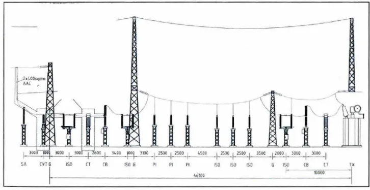
Substation Primary Equipment Under voltage Disturbances Overvoltage Disturbances The Sequence of Power Station
Interconnection of distribution,
communication system Incoming signals into RTU Outgoing signal from R TU Hardware functionality in RTU
control
The implemented telemetry system over WAN Centralize Processing
Distributed Processing Modem SCADA concept
Data Communication Components
Cycle of Modbus master-slave query-response Experion DNP3 architecture
and PAGE 2 5 5 6 12 13 13 14 19 24 25 26 31 32 35 Relation between supported network length and baud rate 36
TCP/IP protocol architecture 38
The Distribution Automation Scheme Research Design Flow
Flowchart of iRTU
Hardware Architecture of iRTU iRTU Power Supply Circuit Voltage Regulator circuit
3.6 PIC16F877A 53
3.7 RTU Main Board Circuit 54
3.8 Analogue Input Circuit 55
3.9 Voltage Divider Circuit 57
3.10 Digital Input Circuit 59
3.11 Optocoupler PC8 I 7 circuit 60
3.12 Digital Output Circuit 61
3.13 System Data Flow Diagram in a UART-interfaced 62
3.14 UART data packet as transmitted through the RF module 63
3.15 Serial Communication Port Circuit 64
3.16 DSl307 Chip 67
3.17 Real Time Clock Circuit 68
3.18 LCD Display 70
3.19 Design used for place part and place wire 73
3.20 Complete iRTU circuit design 74
3.21 Unorganized Components 75
3.22 Components Route 76
3.23 iRTU Complete Board 77
3.24 Upper Layer 78
3.25 Bottom Layer 78
3.26 Flowchart of iRTU MP LAB programming 80
3.27 Flowchart of iRTU Monitoring System 82
3.28 Main Display 84
3.29 Substation A Graph Trending 86
4.1 Substation B Graph Trending 87
4.2 iRTU Prototype 90
4.3 iRTU Casing 90
4.4 Overall iRTU System 94
4.5 Under voltage Fault display 95
4.6 System Monitoring at Master Station 96
4.7 Graph trending for Substation A 97
4.8 Graph trending for substation B 98
4.9 Under voltage graph trending 99
4. 10
4. 11
4. 12
Under voltage fault displayed Overvoltage graph trending Overvoltage fault displayed Constructed Access File
x
100
101
102
APPENDIX
A
B
LIST OF APPENDICES
TITLE
RTU Full Schematic R TU Board Processes
LIST OF ABBREVIATIONS
ABBREVlATION TITLE PAGE
DAS Distribution Automation System
TNB Tenaga Nasional Berhad
2
IPP Independent Power Producers
2
RT U Remote Terminal Unit
6
SCAD A Supervisory Control And Data Acquisition 7
VB Visual Basic
9
GUI Graphical User Interface
9
MTU Master Terminal Unit
12
FRTU Feeder Remote Terminal Unit
12
LV Low Voltage
16
GSM Global System for Mobile
16
PIC Peripheral Interface Controller
16
TCP Transmission Control Protocol
19
UDP User Datagram Protocol
20
RMSC Remote Master Station Centre
21
FPGA Field-Programmable Gate Array
22
CCR Central Control Room
22
SQL Structure Query Language
23
HMI Human Machine Interface
24
PLC Programmable Logic Controller
24
OSI Open System Interconnection
30
ISO International Standard Organization
30
DNP Distributed Network Protocol
30
CAN Controller Area Network
30
IEC International Electro-technical Commission
30
TC P/IP Transmission Control Protocol/Internet Protocol
30
POU Protocol Data Units
31
CRC Cyclic Redundancy Check
34
LRC Longitudinal Redundancy Check
34
EPA Enhanced Performance Architecture
35
SBO Select-Before-Operate
36
IP Internet Protocol
38
ARP Address Resolution Protocol
38
ICMP Internet Control Message Protocol
39
IGMP Internet Group Management Protocol
39
MODEM Modulation and Demodulation Module
41
DS S Distribution Substation
41
DCC Distribution Control Centre
41
PC Personal Computer
42
FLISR Fault Location, Isolation, Service and Restoration
43
RM S Root Mean Square
43
XBee Zig Bee
46
DIP Dual In Package
48
SPI Serial Peripheral Interface
52
I2c
Inter-Integrated Circuit52
UART Universal Asynchronous Receiver Transmitter
52
ADC Analogue to Digital Converter
55
LSB Least Significant Bit
55
TTL Transistor-Transistor Logic
60
CMOS Complementary Metal- Oxide- Semiconductor
60
PMOS P-type Metal-Oxide-Semiconductor
60
NMOS N-type Metal-Oxide-Semiconductor
60
RXff X Receiver/Transmitter
61
RF Radio Frequency
62
RTC Real Time Clock
67
BCD Binary-Coded Decimal
68
PCB Printed Circuit Boards
70
CIS Component Information System
71
LIST OF PUBLICATIONS
PUBLICATION TITLE
Journals:
Papers:
I . M. R. Ab. Ghani, W.N .S.E Wan Jusoh, M. A. M. Hanafiah, S. H. Raman, and Z. Jano, " A Review of Communications Protocol for Intelligent Remote Terminal Unit Development," TELKOMNIKA Telecommunication, Computing, Electronics and Control, vol. 11 , no. 4, 2013. pp 819-829.
2. M.A Mat. Hanafiah, S.H Raman, W.N.S.E Wan Jusoh, M.R Ab Ghani,
and Z. Baharuddin, "Development of a Novel Fault Management m Distribution System using Distribution Automation System m Conjunction with GSM Communication," International Journal of Smart Grid and Clean Energy, vol. 2, no. 3, 2013. pp. 330-335.
I. W.N.S.E. Wan Jusoh, M.R. Ab Ghani, M.A. Mat Hanafiah, and S.H.
Raman. Remote Terminal Unit (RTU) Hardware Design and Development For Distribution Automation System. IEEE Innovative Smart Grid Technologies, May 20-23 , 2014.
2. S.H. Raman, M.R. Ab Ghani, M.A. Mat Hanafiah, and W.N.S.E. Wan
Jusoh. A Human Machine Interface (HMI) Framework for Smart Grid System. IEEE Innovative Smart Grid Technologies, May 20-23 , 2014.
3. W.N. S.E Wan Jusoh, M.A Mat. Hanafiah, M. R. Ab. Ghani, and S. H.
Raman, "Development of A New Modeling Circuit for the Remote Terminal Unit (RTU) with GSM Communication. ," in IEEE Conferences on Clean Energy and Technology (CEAT 2013), Bayview Hotel, 2013. Pp.506-509.
4. W.N.S.E Wan Jusoh, M.A Mat. Hanafiah, M. R. Ab. Ghani, and S. H.
Raman, "Remote Terminal Unit Developed for Distribution Automation System (DAS) using MPLAB Software," in 3rd International
Conferences and Exhibition on Sustainable Energy and Advanced Material, MiTC Melaka, Malaysia, 2013 .
5. S.H Raman, W.N.S.E Wan Jusoh, M.A Mat. Hanafiah, and M.R Ab.
Ghani , " A Low Cost Wireless Data Acquisition System for Distribution Automation System," in 3rd International Conferences and Exhibition on Sustainable Energy and Advanced Material, 2013
6. W.N .S.E Wan Jusoh, M.A Mat. Hanafiah, M.R Ab Ghani, and S.H
Raman, "Remote terminal unit (RTU) hardware design and
implementation efficient in different application." 20 I 3 IEEE 7th
International Power Engineering and Optimization Conference (PEOCO 2013), Langkawi Malaysia, June 2013 , pp. 570-573
7. W.N.S.E Wan Jusoh, M.A Mat. Hanafiah, M .R Ab. Ghani, A. Jidin, and S.H Raman, "Development of Remote Terminal Unit (RTU) for the New Function of Distribution Automation System (DAS)." Power Energy Conversion Symposium, UTeM, Melaka Dec 2012. pp. 310-312
8. S.H Raman, M.R Ab. Ghani, Z. Bharudin, M.A Mat. Hanafiah, and
W.N.S.E Wan Jusoh, "The Implementation of Fault Management in Distribution Automation System Using Distribution Automation System (DAS) in Conjunction with SCADA." Power Energy Conversion Symposium, (PECS2012) UTeM, Melaka Dec 2012. pp. 305-309.
Exhibition: I. iRemote Terminal Unit (iRTU) - UTeMEX 2013
12 December 2013 , UTeM Achievement : Gold Medal
2. iRemote Terminal Unit (iRTU) - 1-ENVEX 2014 11-13 April 2014, UniMAP
Achievement : Gold Medal
3. iRemote Terminal Unit (iRTU) - ITEX 2014
8-10 May 2014, KLCC
Achievement : Gold Medal with Special Award Brussels
CHAPTER 1 INTRODUCTION
1.1 Introduction
This chapter describes the electrical power industry, power outages, the potential industrial usage of RTU devices in their applications, discussing the faults of power disturbances which are studied based on low voltage 400/230V whereby I 0% (overvoltage) and 6% (undervoltage). This chapter also explains about the problems that led to the current issues of encouraging efforts to design and develop iRTU in order to counter the problems with the complete research objectives, research scope and limitation and research contributions to make iRTU relevant and with a good potential to become a device that can contribute to the industry today.
1.2 Background
The operational and maintenance benefits include reducing outage to improve reliability, improving the voltage control, the man hour and man-power which can be reduced also and can enhance fault detection and improve management. For the financial benefits, it can increase income due to quick restoration, improved utilization of system capacity and for client-related benefit, it can give a better service reliability, reduce interruption costs and give a better quality of supply. Meanwhile, the second factor of distribution automation system refers to the distribution substation and feeder automation
and consumer location automation. Distribution substation automation includes the
reclosers, regulators, circuit breakers, load tap changes, switches and to achieve supervisor control function , thus, the remote data acquisition is required. The consumer location automation includes the ability to remotely read the meters, connect or disconnect services and control consumer loads (Parikh, 2009).
SA CVT G ISO ISO G P1 Pl セo@ ISO ISO
'''°'
Figure 1.1 : Substation Primary Equipment
In Malaysia, the power industry is mostly monopolized by Tenaga Nasional Berhad (TNB) whereby almost 60% of power generation in Malaysia is generated by TNB while
the other 40% is supplied by Independent Power Producers (IPPs). Meanwhile the
[image:22.509.68.431.387.574.2]Jusoh et al. , 2013a). The need for more effective and reliable power supply and management increase every year because a lot of energy produced is wasted by improper
planning but essentially, it is caused by the flaws of the power system itself. The
modification can be made at the generation and transmission side can improve the existing power suppl y lies at the distribution side. To identify a fault or a disruption, the efficienc y of the po wer supply in distribution automation will be enhanced in the distribution side . In conventi onal system, when fault occurs, action such as opening and closing of breakers, reclosers and sectionalizing switches at substations are done manually by the substation ' s operator or trained personnel.
The general classes of power quality variations are subdivided into three types which are transient, short duration and long duration. The transients have impulsive and oscillatory cycles of up to 50ms, while for the short duration is between 0.5 cycles and I minutes and for long duration is about less than I minute but the phenomena is not a steady state. This is called instantaneous variations because generally the instantaneous variations are unexpected ; its short term effect affects a facility because it may originate on the utility
line. In this research, the faults tested on the iRTU board are undervoltage and overvoltage
fault which are from the long duration disturbances. According to the TNB electricity system, the transmission voltage networks are 500kV, 275kV and l 32kV, whilst the di stribution voltages are 33kV, l lkV and 400/230 volts. However, in the case of certain parts of Johor and Perak the distribution voltages may also include 22kV and 6.6kV. The
suppl y frequency is 50Hz ± 1 %. The earthing system for low voltage is 400/230V which is
a three phase four wire system, its neutral point solidly earthed with a mixture of overhead lines, underground cables and aerial insulated cables and a mixture of overhead lines, and underground cables and aerial insulated cables. As a guide, the maximum fault levels for the 400/230V voltage systems is related to all equipment proposed to be installed and
conn ected to TNB supply which must comply with the stated short circuit ratings of 31.5 kA (Anon ymous, 2014). The typical voltage of undervoltage fault is 6% which is equal to or below 2 l 6.2V while the overvoltage fault range is l 0% which is equal to 253V or above. The range between 2 l 6.3-252V is considered as a normal condition.
The undervoltage happens when there are long term changes at the input voltage at several parts of equipment. The undervoltage will create some problems such as corroding or loosenjng the customer's wiring connections, conditions of loading phase becomes imbalanced, overloading occurs at the distribution system involving faulty wiring and connection, reclosing activities and incorrect tab setting. The undervoltage can cause the resistance and infrared heating process to take a long, dimming of incandescent light and cause the hardware damage, sensitive equipment malfunction at any time, problem in turning on the fluorescent light, and reduced life and efficiency of electrical equipment e.g. heaters and motors. The solutions to avoid the undervoltage problems are recorded in the load di stribution transformers to several municipal utilities. The record provides the areas prone to the undervoltage condition and people can get earlier warning of that. Besides, the maintenance of appliance must be practiced regularly, so that undervoltage problems
will be reduced. The maintenance focuses more on the cable connections, separated
circuits when transferring loads, transformer tap setting is selected higher, checking for correc t fu se ratings, provide an additional feeder and replacing an overloaded transformer. Figure I .2 shows a graph of undervoltage disturbances.