H
Design and Implementation of Electronic Control
System of Blood Pump for Hemodialysis Machine
Andi Iswahyudi
1, Pratondo Busono
1, Yaya Suryana
1, Anwar Mujadin
1, Dwi Astharini
11
Electrical Engineering, Department of Science and Technology, University Al Azhar of Indonesia, Komplek Masjid Agung Al Azhar Kebayotan Baru, Jakarta Selatan , Kode Pos 12110
E-mail: [email protected], [email protected], [email protected]
Abstract – there are three methods of renal therapies, hemodialysis is the primary choise. This is
because of the cheaper price compared to the CAPD. In addition, people in indonesia are still not understand the CAPD method. However, there are still many problems in the therapy using hemodialysis machine. This research aims to develop and to know the performance of the electronic control system for blood pump to match the ideal flowrate that will be used in hemodialysis treatment. This research resulting the blood pump charateristic is 179,4 step/ml when using glucose 10% and 168,2 step/ml when using glucose 20%. Based on fluid density, glucose 20% have the best performance with relative of error 0,06% at rpm 5 with 400 ml volume desired. From the result with rpm variation, the system has linearity with the slope M = 8970 step/ml = 4,2 rotation/ml using glucose 10%, and M = 8410 step/ml = 3,97 rotation/ml using glucose 20%. Which mean the slope is equivalent with the increased volume around 48,4 - 53,3 ml. It mean the blood pump rotation is constant and the system is working according the flowrate desired. It is found from the result, that many hardware factors can reducing the blood pump performance such as the roller degradation and the flexibility of the hose.
Keywords –Renal Disease, Hemodialysis, CAPD, Blood pump, Flowrate
BACKGROUND
emodialysis,a process where blood is removed from the patient body and pumped into the machine that will filter out toxic substances from the blood, then blood is clean returned again into the body. Principles of Hemodialysis is by applying osmotic process and the artificial kidney ultrafiltration or hemodialysis machines, in removing the remains of the body's metabolism. In hemodialysis process required a hemodialysis machine and a filter as an artificial kidney called a dialyzer, which is used to filter and cleaning the blood from urea, creatinine and metabolic waste substances that are not needed the body.This procedure requires a way into the bloodstream, so that made the connection between an artery and a vein (arteriovenous fistula) through surgery [1]. Controlling blood flowrate is important in hemodialysis therapy. Uncontrolled blood flowrate can dangerous the patients. In the hemodialysis, the blood is taken from the artery and returned process the clean blood to the patient body through vein. The blood is taken from the body using the computer controller peristaltic pump. The purpose
of this research is to design an electronic control system for blood pump used in hemodialysis machine. This pump used peristaltic pump with stepper motor with working flowrate is 200 – 400 ml/min. It is refer to most and frequently of working flowrate during hemodialysis is around 200
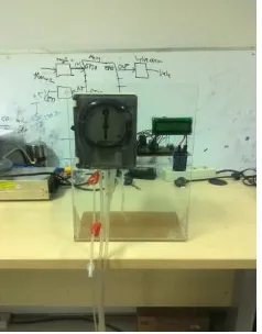
– 400 ml/min [2]. The blood pump prototype will shown in Figure 1.
LITERATURE REVIEW
Blood Pump
Blood pump or peristaltic pump basically works is like the movement that happened in the muscles of the gastrointestinal tract that causes a kind of wave motion causing effects siphoning. In hemodialysis machine peristaltic pump used for pumping variety of fluids. The fluid is contained within a flexible tube fitted inside a circular pump casing (though linear peristaltic pumps have been made). A rotor with a number of rollers attached to the external circumference of the rotor compresses the flexible tube. Usually there will be two or more rollers that occluding the tube, trapping between them a body of fluid. The body of fluid is then transported, at ambient pressure, toward the pump outlet. As the rotor turns, the part of the tube under compression is pinched closed thus forcing the fluid to be pumped to move through the tube. Additionally, as the tube opens to its natural state after the passing of the cam fluid flow is induced to the pump [3].
The
blood pump for hemodialysis machine shown
in Figure 2 [4].
Figure 2. The peristaltic pump [4].
The process of changing the rotation speed from the motor to become flowrate is determined by several parameters, namely length of tube occluded at pump head, the volume of tube, number of rollers, stepper motor rotation in a minute. So it can be expressed in the following equation :
Flowrate =
π
r
2× Lt × n × rev/min
(1)Where L contains length of tube and diameter of the roller, it can be expanded to:
(2)
The final equation of the flowrate is :
Flowrate =
π
2r
2×
R+r+t
× n × rev/min
(3)Or can be simplified :
Flowrate = Vt × Lt × n × Rpm (4)
Where :
Lt : Length of tube between two rollers (cm) R : Radius of pump head(cm)
r : Radius of tube(cm) t : length of tube(cm) Vt : Volume in tube (ml/cm) n : number of roller
Rpm : Rotation of pump (revolution per minute)
In case of emergency, all blood pumps have a way to allow hand cranking. Most often, the pump will have a handle, either with the pump head or one that can be inserted into the pump, which can be used to crank the pump. The pump head should be hand cranked just fast enough to keep the venous pressure at the pre-alarm level [3]. The blood pump construction can be seen in Figure 3 [5].
Figure 3. The construction of peristaltic pump [5]. Peristaltic pump in this research consist of three
part, namely: Stepper motor drive system Mechanical system
Pump head
Stepper Motor Drive System
reliability, efficiency, low level of EMI noise, and free from contamination.
In the stepper motor control, there are three methods that are often used, there is wave drive one phase, hi-torque two phase and half step. Hi-torque method has the advantage have an abundant torque compared with half step method, but in this research high torque is needed because behind the pump head there is mechanical system which is trasferring rotation from stepper motor to pump head. So the method used is hi-torque two phase and torque output from stepper motor can be maximized. The wave drive, hi-torque and half step method can be seen in Figure 4 [7].
Figure 4. Stepper motor drives method [7]. To control this stepper motor there is a difference from most hybrid stepper motors, the difference found in coil configuration which is generally coil 1 to 4 are color-coded red, blue, green, and black on VEXTA stepper motor’s output coil 1 to 4 color code is green, black, red, and blue. In addition to the coil configuration, the step sequence is also different. Sequence of steps for controlling VEXTA stepper motor can be seen in Figure 5 [8].
head because at pumping process need compression to get the fluids and torque for pump head at the same time. The pulley which is connected to stepper motor have less teeth than pulley at pump head which is connected to pump head shaft. The mechanical system inside peristaltic pump and the basic theory can be seen in Figure 6 [9] and 7 [10].
Figure 6. Construction pulley with single belt driven [9].
Figure 7. The gear with belt driven theory [10] Based on that figure we can get the equation of mechanical system is [10] :
D
1n
1= D
2n
2 (5)Figure 5. Step sequence for vexta stepping motor drive [8].
Mechanical System
Mechanical system in peristaltic pump uses single belt transmisson with two shafts and two pulleys. This mechanical system used for drive the pump
Where:
D1 : driver pulley pitch diameter (inch, mm, cm)
n1 : revolution of driver pulley (Rpm)
D2 : driven pulley pitch diameter (inch, mm, cm)
n2 : revolution of driven pulley (Rpm)
Pump Head
St
ep
head is constructed by many parts. Such as cover, hood, rotor/shaft, roller, and spring loaded rollers. The pump head construction can be seen in Figure 8 [11].
Figure 8. Pump head construction for blood pump [11].
RESEARCH METHODS
The framework of this research begins with literature study and patent review, technical specifications, design hardware and software conceptual, detail design, prototyping, system integration, functional testing, and validation. Functional testing consist the mechanism of data collection as follows:
a.Finding ρ of each fluid, by observing changes in the parameter of fluid mass.
b.Finding the blood pump characteristic (ml/step), by observing changes in the parameter of volume and number of steps desired.
c.Finding the relative error of blood pump with variation rpm, by observing changes in the parameter of volume generated and desired volume with variation rpm.
RESULT and DISCUSSION
The testing in this research start with testing the density of 1 litre glucose 10% and 20%. it aims to determine the density of the liquid to be tested on a blood pump. The result of density testing is glucose 10% has density 957 kg/m3 and 20% glucose has density 1,011 kg/m3. The result of testing data can be seen in following Table 1 and Table 2.
Table 1. Testing data result of glucose 10% Larutan gula 10% Table 2. Testing data result of glucose 20%
Larutan gula 20% characteristic based on fluid density can be seen in Figure 9 and Figure 10.
Characteristic of Blood pump
St
Figure 10. Characteristic of blood pump using glucose 20%.
Based on result, the characteristic of blood pump with different density is 179,4 step/ml using glucose 10% and 168,2 step/ml using glucose 20%. Then the relative of error testing will perform based on fluid density and rpm variation. With gear ratio
Figure 13. Testing data result of glucose 10% with Rpm 5.
Figure 14. Testing data result of glucose 20% with Rpm 5.
The result relative of error testing rpm 1 with glucose 10% is -0,992%. It means there is still an error because the torque of stepper motor still not enough to pump glucose 10% to produce desired volume with desired steps based on characteristic of blood pump. Increased speed or rpm the relative Figure 11. Testing data result of glucose 10% with
Rpm 1.
Figure 12. Testing data result of glucose 20% with Rpm 1.
of error will greater than rpm 1. Because the density of glucose 10% less than density of water. The result relative of error testing rpm 5 with glucose 20% is 0,06%. It means there is still a little an error because the torque of stepper motor at rpm 5 more than enough and better to pump glucose 20% which is had higher density than glucose 10%.
CONCLUSION
Based on testing and analysis as written in the previous chapter, it can be concluded as follows:
step/ml using glucose 10% and 168,2 step/ml using glucose 20%.
b.
Based on fluid density of glucose 20% has better performance with relative of error 0,06% at rpm 5 (T5 = 4,7 ms/step) and 400ml volume desired, because the higher density and higher rpm pump will be more accurate.
c.
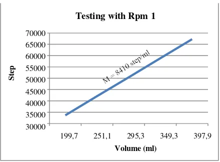
From the result with rpm variation, the system has linearity with the slope M = 8970 step/ml = 4,2 rotation/ml using glucose 10%, and M = 8410 step/ml = 3,97 rotation/ml using glucose 20%. Which mean the slope is equivalent with the increased volume around 48,4 - 53,3 ml. It mean the blood pump rotation is constant and the system is working according the flowrate desired.d.
From the result, many factors can causing the pump performance reduced such as the use of roller, bearing and the flexibility of the hose which is can caused crack.REFERENCES
[1] Hemodialisa,NERS
https://b11nk.wordpress.com/hemodialisa/
(Accessed June 2015.)
[2] Peristaltic Pump, Wikipedia
https://en.wikipedia.org/wiki/Peristaltic_pum p (Accessed June 2015.)
[3] Extracorporeal Circuit, Hemodialysis Devices. http://dialysis-patient- care.blogspot.com/2010/10/hemodialysis- devices-extracorporeal.html. (Accessed June 2015)
[4] http://machinedesign.com/archive/getting- know-stepper-motors.(Accessed June 2015) [5]
https://www.damencnc.com/en/components/ motors-and-drivers/motor-add-ons/245.
(Accessed June 2015)
[6] Motor Stepper
http://ftrbogi.blogspot.com/2011/01/motor- stepper.html. (Accessed June 2015)
[7] http://i.stack.imgur.com/O3elU.png (Accessed June 2015)
[8]
http://www.ni.com/cms/images/devzone/ph/5 4327a871307.gif. (Accessed June 2015) [9]. http://www.designatronics.com/products and
-solutions/timing-pulleys-and-timing-belts.php.
(Accessed June 2015)
[10] http://www.smex.net.au/reference/Vbelts02php.
(Accessed June 2015)
![Figure 3. The construction of peristaltic pump [5].](https://thumb-ap.123doks.com/thumbv2/123dok/2726466.1677125/2.595.97.208.405.517/figure-construction-peristaltic-pump.webp)

![Figure 8. Pump head construction for blood pump [11].](https://thumb-ap.123doks.com/thumbv2/123dok/2726466.1677125/4.595.67.269.133.336/figure-pump-head-construction-blood-pump.webp)