A Voltage Mode Control Maximum Power Point Tracking for
Stand-Alone Photovoltaic System
Jamri M.S
1,a, Kassim A.M
1,b, Hashim M.R
1,c1
Faculty of Electrical Engineering, Universiti Teknikal Malaysia Melaka (UTeM),Durian Tunggal, Malaysia
a
[email protected], [email protected], [email protected]
Keywords: Photovoltaic, voltage mode control DC-DC converter, maximum power point tracking
Abstract. The purpose of this paper is to discuss a modeling and control of stand- alone photovoltaic
system using voltage mode control maximum power point tracking (MPPT) method. The PV module was modeled based on the parameters obtained from a commercial PV data sheet while voltage mode control was modeled using simulink block model. A DC-DC boost converter was chosen to step-up and regulates the input DC voltage of the PV module. The voltage mode control (VMC) maximum power point tracking model was simulated and compared with perturb and observe (P&O) maximum power point tracker in order to validate the performance of output results. Results showed that the voltage mode control maximum power point tracking model yields the similar performance as produced by the photovoltaic system controlled by perturb and observe maximum power point tracking algorithm. The simulation is made to analyze the voltage, current and power generated under the changing irradiant and temperature condition. As a conclusion, the voltage mode control technique is possible to implement which yields the similar performance as the results from conventional MPPT method.
Introduction
The sun light is one of the most important things that very useful for human and nature. It is important in sustaining the way of human nature life. Besides that, it is a very useful to harvest in generating of electricity through the contribution of concentration light. Photovoltaic is a part of renewable energy element which is act as a medium in converting the light into electricity energy. There a few types of photovoltaic system such as grid connected hybrid system photovoltaic, stand-alone photovoltaic system and direct coupled system. Besides, many research and studies had done in term of enhancement of photovoltaic system. The stand-alone PV system is defined as an autonomous system that supplies the electricity without being connected to the utility grid. The installation of the system may include PV array, DC-DC converter, energy storage device, DC-AC inverter and an electrical load. The energy storage device is used to maintain the desired output during the low irradiance or during the night time. Many works have been done in the PV system simulation and modeling. The issue of PV modeling has been discussed in [1]-[5]. This study focus on modeling and control of a standalone photovoltaic system using voltage mode control DC-DC converter method without the connection with energy storage device. This study is only to know the performance of proposed method instead of using maximum power point tracker algorithm to optimize the use of photovoltaic module.
Modeling and simulation
Maximum power point tracker. The photovoltaic module yields the current-voltage characteristic
with a unique point which is known as the Maximum Power Point (MPP) [6].Under the uniform irradiance, the photovoltaic will generate the maximum voltage on its operating point while the current is depends on the load demand. The higher the load demand, the higher the current value would generated by the photovoltaic cell. There are several MPPT control techniques describe in the literature, such as fuzzy logic control, neural network control, pilot cells and digital signal processor based implementation. Nevertheless, Perturb and Observe (P and O) and Incremental Conductance
Applied Mechanics and Materials Vols. 313-314 (2013) pp 503-507 © (2013) Trans Tech Publications, Switzerland
doi:10.4028/www.scientific.net/AMM.313-314.503
(INC) algorithms are most widely used, especially for low-cost implementations [7]-[8]. As shown in the Fig. 1, the MPP changes as a consequence of the variation of the irradiance and temperature level. Therefore, it is necessary to ensure that the PV system always operates at the MPP under uniform irradiance in order to maximize the power harvesting the prevailing environmental conditions.
Figure 1: PV module characteristics curves plotted under changing irradiances
Modelling of perturb and observe (P&O) maximum power point tracker. In P&O MPPT
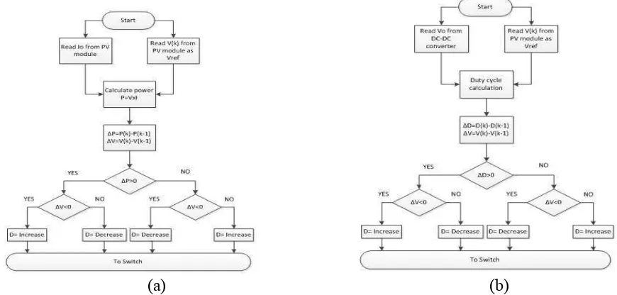
algorithm, a small perturbation is introduced in every iteration to alter the duty cycle value in order to force the operating point to move near the maximum power point. This algorithm compares the power measured in the previous cycle with the power of the current cycle to determine the next perturbation direction [5]. If the power increases due to the perturbation then the perturbation will remain in the same direction. If the operating point exceeds the peak power and deviate to the right side of the P-V characteristic curve, the direction of the perturbation reverses. When the steady-state is reached, the operating point oscillates around the peak power [5] as the MPP will perturb continuously. In order to keep the power variation small, the perturbation size is kept very small yet this will cause the system to respond slowly during transients. The operation of P&O MPPT algorithm is illustrated in the Fig. 2a.
(a) (b)
Figure 2: Flow chart of algorithm (a): Perturb & Observe MPPT (b): Voltage Mode Control MPPT
Modelling of voltage mode control (VMC) maximum power point tracker. In VMC method,
the DC-DC boost converter was used and operated in closed-loop and automatic variation of switching duty cycle. It senses the value of output voltage from photovoltaic module as a reference and sense the output voltage of DC-DC boost converter as a current step voltage. These two values are then used to calculate the value of duty cycle by using the basic input/output DC-DC boost converter equation. In order to force the operating point to move near to the maximum power point, it is necessary to compares the PV voltage measured of the previous cycle with the PV voltage of the current cycle to determine the next increment and decrement decision. Same like to the P&O MPPT algorithm, the direction of increment and decrement of duty cycle is remain the same. The variation of PV output voltage would affect the increment/decrement of duty cycle value. The operation of the proposed MPPT controller is illustrated in the Fig. 2b.
0 5 10 15 20 25
Simulation setup. In order to validate the voltage mode control MPPT model, a circuitry simulation of the proposed PV system is performed. With using the same parameters, this circuit is connected in parallel with the PV conventional system model which used the P&O MPPT controller as shown in Fig. 3. Both of models were developed in MATLAB/Simulink. The switching operation for DC-DC boost converter was designed to operate at 20 kHz and has the inductor of 20 mH and capacitor of 2 mF respectively to generate small output ripple which is less than 1%. The system was tested under a variation of irradiance and temperature levels. The load is a pure resistive load of 10 Ω.
PV Module DC-DC Boost Converter Load
VMC MPPT
Figure 3: The block diagram of experiment setup
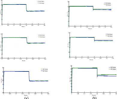
Results.Figure 4a show the results of comparison between both methods at the output of DC-DC
boost converter side under changing of solar irradiance, while Fig. 4b shows the simulation results at the output of DC-DC boost converter side under changing of temperature.
(a) (b)
Figure 4: The DC-DC converter simulation output (a) Changing of irradiance, (b) Changing of temperature
Analysis and Discussion. The simulation results show that the photovoltaic system generates an
average of 42 W, 21 V of voltage and 2.2 A of current under the nominal irradiance and temperature. This output may change as the irradiance and temperature level changes as shown in Fig. 4a and Fig.
0 0.05 0.1 0.15 0.2 0.25 0.3 0.35
4b. Due to the fixed step-size used in the MPPT, the maximum power point tracking controller brings the photovoltaic module output continuously oscillates around the maximum power point. The oscillation occur during the transient as shown in Fig.4b is attributed to the switching action of the boost converter and the fixed step size of the MPPT algorithm.
The results show that the system operated with voltage mode control (VMC) MPPT model yields the similar waveform shape with the one produced by the system combined with perturb and observe (P&O) MPPT model. The amplitude of the output waveform decreases when the irradiance decreased. It can be noticed that the voltage mode control (VMC) MPPT method make the output voltage and output power of boost converter are slightly higher than perturb and observe (P&O) MPPT method. This is because the algorithm of voltage mode control (VMC) MPPT method is only measured the step size of output voltage between the photovoltaic module and boost converter. Compare to perturb and observe (P&O) MPPT algorithm which measured the current value to calculate power and make the output current of boost converter slightly higher.
Acknowledgements.
This research was supported by grant from Universiti Teknikal Malaysia Melaka award no. PJP/2012/FKE(6A)/S01091.
Conclusion.
This paper has presented the modeling of a standalone PV system using voltage mode control MPPT method. The details of the modeling technique and circuitry simulation were described and comparisons was made with the conventional perturb and observe MPPT technique. The objective of this method is to control and optimize the output of photovoltaic system and validate with the one of conventional MPPT technique simulation. Analysis of the results shows that the model yields the similar performance.
The voltage mode control MPPT method is possible to implement in a modeling and control of photovoltaic system because the model yields the similar performance as the results from perturb and observe MPPT method which may help to reduce the overall complexity of conventional MPPT algorithm.
References
[1] Theocharis, A.D., A. Menti, J. Milias-Argitis and T. Zacharias, 2005. Modeling and simulation of a single-phase residential photovoltaic system. Proceeding of the IEEE Russia Power Tech, June 27-30, IEEE Computer Society, St. Petersburg, pp: 1-7. DOI: 10.1109/PTC.2005.4524407
[2] Ropp, M.E. and S. Gonzalez, 2009. Development of a MATLAB/simulink model of a single-phase grid connected photovoltaic system. IEEE Trans. Energy Conver., 24: 195-202. DOI: 10.1109/TEC.2008.2003206
[3] Ito, R., Y. Matsuzaki, T. Tani and T. Yachi, 2003. Evaluation of performance of MPPT equipment in photovoltaic system. Proceeding of the 25th International Telecommunications
Energy Conference, Oct. 19-23, IEEE Computer Society, USA.,pp:256-260.DOI:
10.1109/INTLEC.2003.1252122
[4] Bae, H.S., J.H. Park, B.H. Cho and G.J. Yu, 2005. New control strategy for 2-stage utility-connected photovoltaic power conditioning system with a low cost digital processor.
Proceedings of the IEEE 36th Power Electronics Specialists Conference, June 16-16, IEEE Xplore Press, pp: 2925-2929.
[5] Armstrong, S. and W.G. Hurley, 2004. Self-regulating maximum power point tracking for solar energy systems. Proceeding of the 39th International Universities Power Engineering Conference, Sept. 6-8, University of the West of England (UWE), Bristol, UK., pp: 1339-1350.
[6] Femia, N., G. Petrone, G. Spagnuolo and M. Vitelli, 2005. Optimization of perturb and observe maximum power point tracking method. IEEE Trans. Power Elect., 20: 963-973. DOI: 10.1109/TPEL.2005.850975
[7] Mahmoud, A.M.A., H.M. Mashaly, S.A. Kandil, H. El Khashab and M.N.F. Nashed, 2000. Fuzzy logic implementation for photovoltaic maximum power tracking. Proceeding of the 26th Annual Conference of the IEEE International Workshop on Robot and Human Interactive
Communication, Oct. 22-28, IEEE Computer Society,pp: 735-740. DOI:
10.1109/IECON.2000.973240
[8] Marouani, R. and F. Bacha, 2009. A maximum-power point tracking algorithm applied to a photovoltaic water-pumping system. Proceeding of the 8th International Symposium on Advanced Electromechanical Motion Systems and Electric Drives Joint Symposium, Sept. 2009, pp:16.DOI:10.1109/ELECTROMOTION.2009.5259078