PROFIL PENYELIDIKAN
PC-BASED FOR POWER FAILURE MONITORING
Principal Researcher:
YUSMARNITA BINTI YUSOP
Co-researcher:
Siti Huzaimah binti Husin, Zulhairi bin Othman, Siva Kumar a/l Subramaniam
UNIVERSITI TEKNIKAL MALAYSIA MELAKA
Email: [email protected]
ABSTRACT
CHAPTER I
INTRODUCTION
This chapter will give reader a basic introduction to how the idea of this
project generated. The chapter contains introduction, objective of the project,
problem statement, scopes of work, brief methodology, and report structure.
1.0 Introduction
There has been tremendous rise in number of mobile customers in world (> 2
billion). Due to widespread growth of cellular network and drastic reduction in call
rates and lower-end handsets, mobile usage has percolated all sections of society.
Latest mobiles can not only allow you to click pictures, play music, store your
address book, hook you to Internet, download e-mails, guide you through maze of
city streets but also enable you to watch latest blockbusters, favorite TV programs,
book tickets and transact business. In recent years, a system is developed for remote
monitoring and control of devices using mobile through spoken commands. The
system offer several attractive features like:
• control from anywhere in world if cellular coverage is available acknowledgement about execution of command from system to user
• alerts user on occurrence of any abnormal
• conditions like power failure, parameters
• exceeding prescribed limits, etc.
• ease of implementation and cost-effective approach.
In a remote system monitoring application, a program (sometimes with the
help of a group of sensors) is constantly monitoring the status of a remote system. If
a certain condition is satisfied, the program will send a text message to the system
administrator to notify him/her of the situation.
This project title is “PC-based power failure monitoring with SMS
notification”. This project is an upgraded version of the current project. Very often,
unstable voltage from the main power supply and power trips are encountered in the
laboratory which will not only cause subsequent damages to sensitive equipment but
also affect the learning process during experiments. Current project only achieved up
parameters of voltage, current, power and faulty power points on the screen of PC.
The current system only can give alert to person in charge by displaying warning
message through PC. In order to improve current project, GSM modem will be
implemented to send notification via SMS. This project use NI LabVIEW software to
create a front panel of virtual instrument. The data acquisition module, NI DAQ
(USB 6009) device is used for real time monitoring and it provides interfacing
between hardware and software. Transducer is used to convert the measured voltage
to DAQ readable voltage level. GSM modem is used to interface between the PC and
the mobile phone. So, the system will send out a SMS to person in charge as warning
if any abnormal of voltage level has occurred. This project is shown in the block
1.1 Objectives
The main purposed of this project are to design and implement a PC-based
power failure monitoring with via SMS System. Therefore, the objectives as below
should be achieved.
i. To design and develop the PC-Based Power Failure Monitoring with via
SMS System by using LabVIEW.
ii. To design and develop the interfacing between software and control circuit
by using GSM modem and LabVIEW.
iii. To monitor the operated power point, and close all the power point in one
time through the front panel with SMS notification.
iv. To allow person in charge to take immediately action by using SMS
notification when the unstable voltage level has occurred.
1.2 Problem Statement
Generally, electrical power is one of the importance basic necessary in our
life. It has been used for driving the electrical and electronic equipments in our daily
life to perform some tasks. Present equipment setups and devices used in commercial
and industrial facilities, such as digital computers, power electronic devices, and
automated equipment, are sensitive to many types of power disturbances. Power
disturbances arising within facilities have increased significantly due to the
increasing use of energy efficient equipment such as switch-mode power supplies,
inverters for variable speed drives, and more. The monitoring, data collection and
alerts user on occurrence of any abnormal for power quality study therefore has to be
conducted. In the other side, the situation of power trip is one of the phenomenons
that always happen in the laboratory. Therefore, an alert system is necessary used to
alert the responsible people immediately and take immediate action to prevent or safe
our valuable things. For this situation, human need a system to help and initiate
actions to alert or warn people who are in responsible, and to seek assistance before
they are in danger. Therefore, “PC-Based Power Failure Monitoring with via SMS
1.3 Scope of Work
The scopes of works in this project are:
i. LabVIEW is used to create the front panel of virtual instrument.
ii. NI DAQ 6009 is a data acquisition unit that used to interfacing
between hardware and software.
iii. GSM modem is used to interfacing between the PC and mobile phone
through via SMS if any abnormal of the system has occurred.
iv. AT commands is used for controlling the functionality of modem.
v. The cellular phone is used to send/receive a message for
monitoring/control the condition of power point.
1.4 Brief Explanation of Methodology
First of all, this project is beginning by having a discussion with supervisor
about the general ideas and concepts that would be used in this project. Next, for
literature review stage, the background of this project is studied and research is done
by referring various sources like: reference book, I.E.E.E journals, website of
National Instrument, and data sheet. For the following stage, all the information
related to components, DAQ, GSM modem information is seeking, and the most
suitable would be selected for used in this project. On next stage, the LabVIEW
programming is studied, and the front panel of virtual instrument is created and
simulated. Hardware interfacing would be studied on the following stage. After that,
the hardware for this project is built and assembled; and the system is ready for
overall system testing. If the outputs of this system fulfill the project requirements
and specification, so this project is considered success. If the output of this system
did not fulfill the desired output, so the troubleshooting would be carry out until it
1.5 Report Structure
This report is documentary delivering the ideas generated, concepts applied,
activities done, and finally the product of project itself. It consists of five chapters.
Following is a chapter-by-chapter description of information in this report.
Chapter 1 gives reader a basic introduction to how the idea of this project
generated. The chapter contains introduction, objective of the project, problem
statement, scopes of work, brief methodology, and report structure.
Chapter 2 is a literature review on theoretical concepts applied in this project.
The chapter concludes the background study of power system, PC-based monitoring
system. Besides that, this chapter also explains how the PC-based monitoring power
failure with SMS notification work, what is LabVIEW, what is DAQ, what is GSM
modem and application of others component. Then, why choose the specific DAQ,
GSM modem, and related components.
Chapter 3 introduces the methodology of the project. The chapter contains the
flow chart which explains the overall method taken along the project carry out.
Besides that, this chapter also introduces the construction of the project, which
involves hardware development and software development. Basically, the hardware
development for the project concludes with front panel LabVIEW design, block
diagram design, and study AT commands for GSM modem. Besides, the software
development of project will discuss what graphical programming is, how to use the
LabVIEW, and how to implement it on this project.
Chapter 4 will be covered all the result from designing process. It will also
include a discussion about the project. The chapter concludes with discussion on
front panel of virtual instrument and control circuit for the system.
Chapter 5 will be conclusion of the project. The chapter concludes with some
CHAPTER II
LITERATURE REVIEW
This chapter is a literature review on theoretical concepts applied in this
project. The chapter concludes the background study of power system, PC-based
monitoring system. Besides that, this chapter also explains how the PC-based power
failure monitoring with SMS notification work, what is LabVIEW, what is DAQ,
what is GSM modem and application of others component. Then, why choose the
specific DAQ, GSM modem, and related components.
2.1 Introduction
Throughout the world, there have been many researches about the concept
and implementation of this PC-based power failure monitoring with SMS
notification system. This project is implemented to enhance the available similar
system with additional functions and applied it on the Laboratory of Electronic
Industrial at UTeM.
Literature reviews are based in information obtained from valid sources such
as books, articles of relevance, published paper or any other source deemed
appropriate. One of the more famous sources for literature reviews from IEEE,
York, USA. The forms of literature include standards of practice, proceeding paper
or conference papers such as those from the Power Engineering Conference.
2.2 Introduction to SMS
SMS appeared on the wireless scene in 1991 in Europe. The European
standard for digital wireless, now known as the Global System for Mobile
Communications (GSM), included short messaging services from the outset.
In North America, SMS was made available initially on digital wireless
networks built by early pioneers such as BellSouth Mobility, PrimeCo, and Nextel,
among others. These digital wireless networks are based on GSM, code division
multiple access (CDMA), and time division multiple access (TDMA) standards.
Network consolidation from mergers and acquisitions has resulted in large
wireless networks having nationwide or international coverage and sometimes
supporting more than one wireless technology. These new classes of service
provider’s demands network-grade products that can easily provide a uniform
solution, enable ease of operation and administration, and accommodate existing
subscriber capacity, message throughput, future growth, and services reliably. Short
messaging service center (SMSC) solutions based on an intelligent network (IN)
approach are well suited to satisfy these requirements, while adding all the benefits
of IN implementations.
SMS provides a mechanism for transmitting short messages to and from
wireless devices. The service makes use of an SMSC, which acts as a
store-and-forward system for short messages. The wireless network provides the mechanisms
required to find the destination station(s) and transports short messages between the
SMSCs and wireless stations. In contrast to other existing text-message transmission
services such as alphanumeric paging, the service elements are designed to provide
guaranteed delivery of text messages to the destination. Additionally, SMS supports
several input mechanisms that allow interconnection with different message sources
A distinguishing characteristic of the service is that an active mobile handset
is able to receive or submit a short message at any time, independent of whether a
voice or data call is in progress (in some implementations, this may depend on the
MSC or SMSC capabilities). SMS also guarantees delivery of the short message by
the network. Temporary failures due to unavailable receiving stations are identified,
and the short message is stored in the SMSC until the destination device becomes
available.
SMS is characterized by out-of-band packet delivery and low-bandwidth
message transfer, which results in a highly efficient means for transmitting short
bursts of data. Initial applications of SMS focused on eliminating alphanumeric
pagers by permitting two-way general-purpose messaging and notification services,
primarily for voice mail. As technology and networks evolved, a variety of services
have been introduced, including e-mail, fax, and paging integration, interactive
banking, information services such as stock quotes, and integration with
Internet-based applications. Wireless data applications include downloading of subscriber
identity module (SIM) cards for activation, debit, profile-editing purposes, wireless
points of sale (POSs), and other field-service applications such as automatic meter
reading, remote sensing, and location-based services. Additionally, integration with
the Internet spurred the development of Web-based messaging and other interactive
applications such as instant messaging, gaming, and chatting.
2.2.1 Benefits of SMS
In today's competitive world, differentiation is a significant factor in the
success of the service provider. Once the basic services, such as voice telephony, are
deployed, SMS provides a powerful vehicle for service differentiation. If the market
allows for it, SMS can also represent an additional source of revenue for the service
provider.
The benefits of SMS to subscribers center on convenience, flexibility, and
seamless integration of messaging services and data access. From this perspective,
the primary benefit is the ability to use the handset as an extension of the computer.
can be integrated into a single wireless device—the mobile terminal. These benefits
normally depend on the applications that the service provider offers. At a minimum,
SMS benefits include the following:
Delivery of notifications and alerts
Guaranteed message delivery
Reliable, low-cost communication mechanism for concise information
Ability to screen messages and return calls in a selective way
Increased subscriber productivity
More sophisticated functionality provides the following enhanced subscriber benefits:
Delivery of messages to multiple subscribers at a time
Ability to receive diverse information
E-mail generation
Creation of user groups
Integration with other data and Internet-based applications
The benefits of SMS to the service provider are as follows:
Ability to increment average revenue per user (due to increased number of calls on wireless and wire line networks by leveraging the notification
capabilities of SMS)
An alternative to alphanumeric paging services, which may replace or complement an existing paging offer
Ability to enable wireless data access for corporate users
New revenue streams resulting from addition of value-added services such as e-mail, voice mail, fax, and Web-based application integration, reminder
service, stock and currency quotes, and airline schedules
Provision of key administrative services such as advice of charge, over-the-air downloading, and over-the-over-the-air service provisioning
Notification mechanisms for newer services such as those utilizing wireless application protocol (WAP)
2.2.2 SMS Applications
SMS was initially designed to support limited-size messages, mostly
notifications and numeric or alphanumeric pages. While these applications are and
will continue to be widely used, there are more recent niches that SMS still can
exploit.
Short bursts of data are at the heart of many applications that were restricted
to the world of data networks with fixed terminals attached to a local-area network
(LAN) or wide-area network (WAN). However, many of these applications are better
served if the data communication capabilities could be added to the mobility of the
station. Thus, a waiter who can charge a customer's credit card right at the table, at
any time, instead of going to a fixed POS terminal located by the register will be able
to help customers in a faster, more convenient way.
Also, the ability to track the location of a moving asset such as a truck or its
load is very valuable for both providers and clients. This application, again, just
needs to interchange small amounts of information, such as the longitude and latitude
at a current time of the day, and perhaps other parameters like temperature or
humidity.
This application does not necessarily require the monitored entity to be in
movement. The requirements are basically short, busty data and a location that has
digital network coverage. For example, in a neighborhood, it would be faster, easier,
and cheaper to drive a truck from the local power company, which interrogates
intelligent meters to obtain their current readings and then forwards them via short
message to a central data processing center to generate the billing. Similarly, delivery
trucks could be alerted of the inventory of a customer running low, when the truck is
close to the customer’s facilities. The truck driver could place a quick phone call to
Another family of applications that can use SMS as a data transport
mechanism is banking. It is no secret that automated teller machine (ATM) and
Internet transactions are less costly than transactions completed at a branch. Internet
transactions are even cheaper than ATM transactions. Therefore, enabling wireless
subscribers to check their balances, transfer funds between accounts, pay their bills
and credit cards is valuable, not only for the subscriber but also for financial
institutions.
Entertainment applications are also good drivers of SMS usage. Examples of
these are simple short message exchanges between two parties (“texting”) or between
multiple participants (“chat”). Also, delivery of information that the subscriber can
tailor to his or her lifestyle represents an attractive proposition for wireless users.
Wireless Web browsing allows the users to search for information without the
physical restrictions of a PC. College students certainly appreciate not having to go
to the computer lab or their dorm to check e-mail or find out what the required book
is for the semester that is about to start.
E-mail continues to be by far the most used wireless data application.
However, handsets are evolving quickly and are including more and more
functionality that supports newer applications at the same time that user friendliness
increases. Probably the next big success beyond wireless Web will be Internet
shopping and other e-commerce applications such as electronic coupons, advertising,
etc.
The potential for applications is enormous, and new needs appear to arise
constantly, demanding a solution that may travel over SMS.
2.3 LabVIEW
LabVIEW (short for Laboratory Virtual Instrumentation Engineering
Workbench) is a powerful and flexible instrumentation and analysis software
LabVIEW is commonly used for data acquisition, instrument control, and industrial
automation on a variety of platforms including Microsoft Windows, various flavors
of UNIX, Linux, and Mac OS. The latest version of LabVIEW is version 8.5,
released in August of 2007.
2.3.1 LabVIEW Programming
LabVIEW has been used as the main platform in this project. LabVIEW is a
modern graphical programming language that has been widely adopted throughout
industry, academia, and government lab as the standard for data acquisition,
instrument control software, and analysis software [1]. Furthermore, LabVIEW is a
scientific and engineering rapid application development environment specialized
towards data acquisition, electronic measurement, and control applications.
LabVIEW can be used to handle data acquisition in easier way compared to text
based programming language.
Wells [3] has explained that the LabVIEW programs are called virtual
instruments (VIs). Virtual instrument system such as LabVIEW inevitably invites
comparison to real physical instrumentation [2]. Basically, there are three main parts
of a VI which are: the front panel, the block diagram, and the icon. The main
purposes of the front panel are to get the input values and to view the outputs from
the VI block diagram. Each front panel has an accompanying block diagram, which
is the VI program. The block diagram can be assumed as source code. Finally, the
function of the icon is to turn a VI into an object that can be used in the block
diagrams of other VIs as it were a subroutine. Wells [3] also mentioned that ‘the icon
and the connector of a VI allow other VIs to pass data to the VI’.
2.3.2 Advantages of Using LabVIEW
Virtual instrumentation offers the greateast benefit over real instruments in
the areas of price, performance, flexibilty, and customization [2]. One benefit of
accessing instrumentation hardware. Drivers and abstraction layers for many
different types of instruments and buses are included or are available for inclusion.
These present themselves as graphical nodes. The abstraction layers offer standard
software interfaces to communicate with hardware devices. The provided driver
interfaces save program development time. Therefore, that even people with limited
coding experience can write programs and deploy test solutions in a reduced time
frame when compared to more conventional or competing systems. A new hardware
driver topology (DAQmxBase), which consists mainly of ''G''-coded components
with only a few register calls through NI Measurement Hardware DDK (Driver
Development Kit) functions, provides platform independent hardware access to
numerous data acquisition and instrumentation devices. The DAQmxBase driver is
available for LabVIEW on Windows, MacOSX and Linux platforms.
In terms of performance, LabVIEW includes a compiler that produces native
code for the CPU platform. The graphical code is translated into executable machine
code by interpreting the syntax and by compilation. The LabVIEW syntax is strictly
enforced during the editing process and compiled into the executable machine code
when requested to run or upon saving. In the latter case, the executable and the
source code are merged into a single file. The executable runs with the help of the
LabVIEW run-time engine, which contains some precompiled code to perform
common tasks that are defined by the G language. The run-time engine reduces
compile time and also provides a consistent interface to various operating systems,
graphic systems, hardware components, etc. The run-time environment makes the
code portable across platforms. Generally, LV code can be slower than equivalent
compiled C code, although the differences often lie more with program optimization
than inherent execution speed.
Many libraries with a large number of functions for data acquisition, signal
generation, mathematics, statistics, signal conditioning, analysis, etc., along with
numerous graphical interface elements are provided in several LabVIEW package
options. The LabVIEW Professional Development System allows creating
stand-alone executables and the resultant executable can be distributed an unlimited
number of times. The run-time engine and its libraries can be provided freely along
A benefit of the LabVIEW environment is the platform independent nature of
the ''G''-code, which is (with the exception of a few platform-specific functions)
portable between the different LabVIEW systems for different operating systems
(Windows, MacOSX and Linux). National Instruments is increasingly focusing on
the capability of deploying LabVIEW code onto an increasing number of targets
including devices like Phar Lap OS based LabVIEW real-time controllers,
PocketPCs, PDAs, FieldPoint modules and into FPGAs on special boards.
LabVIEW has proven to be an invaluable tool in reducing development time.
Because LabVIEW offers unique advantages over traditional development
environments, it is the standard for measurement and automation. LabVIEW has
evolved along with PC technology, providing the ability to seamlessly upgrade your
applications while taking full advantage of continuous improvements in processing
speed and performance of commercial technology.
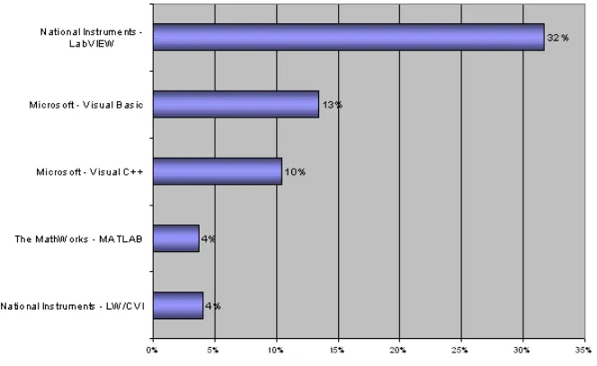
Market research shows the widespread adoption of LabVIEW for data
acquisition and control applications. The following findings illustrate that many
engineers and scientists prefer LabVIEW and National Instruments products over
other options for their PC-based data acquisition and test instrumentation needs. The
research for Most-Used Software for Data Acquisition and Instrument Control –
Product Awareness Study Conducted by Reed Research Group, Sponsored by
National Instruments, Q1 2004 is shown as below:
2.4 WaveCom M1306B GSM/GPRS-Modem (Fastrack Modem)
Wavecom's rugged, discrete Fastrack GSM/GPRS modem has proven itself
for stable, reliable performance on wireless networks for more than five years. Fully
certified, the dual band 900/1800MHz Fastrack M1306B offers GPRS Class 10
Capability with Open AT and IT protocols such as IP connectivity as standard
features.
The WaveCom M1306B GSM/GPRS-Modem Fastrack Modem can be used
with ActiveXperts SMS Messaging Server to send and receive SMS messages.
a) Hardware
Figure 2.2: GSM Modem
Wavecom’s rugged, discrete Fastrack GSM/GPRS modem has proven itself
for stable, reliable performance on wireless networks worldwide for more than five
years. Updated with new features, the now legendary Fastrack continues to deliver
rapid time to market and painless integration for machine-to-machine applications.
Housed in a rugged metallic casing, 25 mm shorter than the previous version, the
Fastrack M1306B now offers two general purpose input/output access points to
connect peripherals. Fully certified, the dual-band 900/1800 MHz Fastrack M1306B
offers GPRS Class 10 capability, supports Open AT and IT protocols such as IP
connectivity.
It is included as part of the basic Autopage Package. Most Autopage users
used for many other purposes. We supply it with a 240V mains power supply, a
straight helical aerial and an RS232 data cable to connect it to your computer.
b) Features
• EGSM 900/1800MHz
• Supports voice / data / fax / SMS (text and PDU modes) / GPRS class 10
• Open AT capable for embedded applications
• Optional TCP/IP stack permitting direct UDP/TCP connectivity and POP3/SMTP/FTP services
• 3V SIM Interface
• 15-pin sub-D connector for voice and RS-232 serial interface
• Fully type-approved
• 25mm shorter than M1206B predecessor
• Serial port shutdown power saving feature
• Two general-purpose input/output pins built into Molex power connector
• Compatible with all laptops and PCs installed with Win 98SE / 2000 / ME / XP, Linux and Mac Os
c) Details
• Band: Dual-band EGSM900/1800 MHz
• Dimensions: 73x54x25mm
• Weight: 82g
• Input Voltage: 5.5 to 32v DC
• Power Supply: 14mA in idle mode with no RS232 communication @ 5.5VDC, 31mA in idle mode with active RS232 communication at
5.5VDC.
2.4.1 Wavecom Products
Wavecom provide three distinct product families aimed at the M2M
For those requiring a stand-alone wireless communication solution,
Wavecom's Fastrack modem is a natural choice. A fully functional GSM/GPRS
modem with data, voice, fax and SMS capability, the Fastrack features an internal
SIM tray and SIM interface, a 15-pin sub-D RS232 interface for serial
communication, and a 4-pin Molex connector allowing it to be powered from a
5.5-32VDC supply or one of our mains adaptors.
All Wavecom products are controlled by an extended version of the Hayes
AT command set. For added functionality, we offer Wavecom's OpenAT software
development kit (SDK), which allows embedded programs to be written in C code.
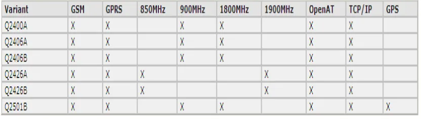
a) WISMO Quik
The WISMO Quik is a small footprint, ultra-slim wireless module with full
GSM/GPRS capability (Q2500 series also features GPS) including data, voice, fax
and SMS. Automotive versions of WISMO Quik are available.
Table 2.1: Features GPS of WISMO GSM Product.
b) Integra
To both ease product development and reduce time-to-market, we also supply
the Integra modem - essentially a Quik module housed in a tough metallic casing
with internal SIM tray and built-in interfaces for the SIM, serial communications,
Table 2.2: Features GPS of Integra GSM Product.
c) Fastrack
For those requiring a stand-alone wireless communication solution,
Wavecom's Fastrack modem is a natural choice. A fully functional GSM/GPRS
modem with data, voice, fax and SMS capability, the Fastrack features an internal
SIM tray and SIM interface, a 15-pin sub-D RS232 interface for serial
communication, and a 4-pin Molex connector allowing it to be powered from a
5.5-32VDC supply or one of our mains adaptors.
Table 2.3: Features GPS of Fastrack GSM product.
2.5 AT Commands Interface
AT commands are instructions used to control a modem. AT is the
abbreviation of ATtention. Every command line starts with "AT" or "at". That's why
modem commands are called AT commands. Many of the commands that are used to
control wired dial-up modems, such as ATD (Dial), ATA (Answer), ATH (Hook
control) and ATO (Return to online data state), are also supported by GSM/GPRS
modems and mobile phones. Besides this common AT command set, GSM/GPRS
modems and mobile phones support an AT command set that is specific to the GSM
technology, which includes SMS-related commands like AT+CMGS (Send SMS
message), AT+CMSS (Send SMS message from storage), AT+CMGL (List SMS
messages) and AT+CMGR (Read SMS messages).
Note that the starting "AT" is the prefix that informs the modem about the
the actual AT command name in ATD and +CMGS is the actual AT command name
in AT+CMGS. However, some books and web sites use them interchangeably as the
name of an AT command.
Here are some of the tasks that can be done using AT commands with a
GSM/GPRS modem or mobile phone:
Get basic information about the mobile phone or GSM/GPRS modem. For example, name of manufacturer (AT+CGMI), model number
(AT+CGMM), IMEI number (International Mobile Equipment Identity)
(AT+CGSN) and software version (AT+CGMR).
Get basic information about the subscriber. For example, MSISDN (AT+CNUM) and IMSI number (International Mobile Subscriber Identity)
(AT+CIMI).
Get the current status of the mobile phone or GSM/GPRS modem. For example, mobile phone activity status (AT+CPAS), mobile network
registration status (AT+CREG), radio signal strength (AT+CSQ), battery
charge level and battery charging status (AT+CBC).
Establish a data connection or voice connection to a remote modem (ATD, ATA, etc).
Send and receive fax (ATD, ATA, AT+F*).
Send (AT+CMGS, AT+CMSS), read (AT+CMGR, AT+CMGL), write (AT+CMGW) or delete (AT+CMGD) SMS messages and obtain
notifications of newly received SMS messages (AT+CNMI).
Read (AT+CPBR), write (AT+CPBW) or search (AT+CPBF) phonebook entries.
Perform security-related tasks, such as opening or closing facility locks (AT+CLCK), checking whether a facility is locked (AT+CLCK) and
changing passwords (AT+CPWD). (Facility lock examples: SIM lock [a
password must be given to the SIM card every time the mobile phone is
switched on] and PH-SIM lock [a certain SIM card is associated with the
mobile phone. To use other SIM cards with the mobile phone, a password
Control the presentation of result codes / error messages of AT commands. For example, you can control whether to enable certain error messages
(AT+CMEE) and whether error messages should be displayed in numeric
format or verbose format (AT+CMEE=1 or AT+CMEE=2).
Save and restore configurations of the mobile phone or GSM/GPRS modem. For example, save (AT+CSAS) and restore (AT+CRES) settings
related to SMS messaging such as the SMS center address.
Note that mobile phone manufacturers usually do not implement all AT
commands, command parameters and parameter values in their mobile phones. Also,
the behavior of the implemented AT commands may be different from that defined in
the standard. In general, GSM/GPRS modems designed for wireless applications
have better support of AT commands than ordinary mobile phones.
In addition, some AT commands require the support of mobile network
operators. For example, SMS over GPRS can be enabled on some GPRS mobile
phones and GPRS modems with the +CGSMS command (command name in text:
Select Service for MO SMS Messages). But if the mobile network operator does not
support the transmission of SMS over GPRS, you cannot use this feature.
2.5.1 Basic Commands and Extended Commands
There are two types of AT commands: basic commands and extended
commands. Basic commands are AT commands that do not start with "+". For
example, D (Dial), A (Answer), H (Hook control) and O (Return to online data state)
are basic commands. Extended commands are AT commands that start with "+". All
GSM AT commands are extended commands. For example, +CMGS (Send SMS
message), +CMSS (Send SMS message from storage), +CMGL (List SMS messages)
2.6 Data Acquisition
At the simplest level, data acquisition can be accomplished manually using
paper and pencil, recording readings from a multimeter or any other instrument. For
some applications this form of data acquisition may be adequate. However, data
recording applications that require large number of data readings where very frequent
recordings are necessary must include instruments or microcontrollers to acquire and
record data precisely (Rigby and Dalby, 1995) [4].
Data acquisition is the sampling of the real world to generate data that can be
manipulated by a computer. Data acquisition typically involves acquisition of signals
and waveforms and processing the signals to obtain desired information. The
components of data acquisition systems include appropriate sensors that convert any
measurement parameter to an electrical signal, which is acquired by data acquisition
hardware. Acquired data is displayed, analyzed, and stored on a computer. LabVIEW
offers a graphical programming environment optimized for data acquisition.
2.6.1 NI DAQ USB 6009
Figure 2.3: NI DAQ USB 6009
The NI USB-6009 is a USB-based data acquisition (DAQ) and control device
capabilities with eight channels of 14-bit analog input, two analog outputs, 12 digital
I/O lines and one counter. This devices draw power from the USB bus, so it does not
require an external power supply to operate. It include removable screw terminals
for direct signal connectivity, an onboard voltage reference for powering external
devices and sensors, a four-layer board design for reduced noise and improved
accuracy and over voltage protection on analog input lines up to 35 V. In addition to
ready-to-run data-logging software, each device includes NI-DAQmx Base
measurement services driver software for programming the device in LabVIEW or C.
a) Main Features of NI USB-6009
i. Analog input (AI): 8 inputs with referenced single ended signal coupling
or 4 inputs with differential signal coupling. Software-configurable
voltage ranges: ±20V, ±10V, ±5V, ±4V, ±2.5V, ±2V, ±1.25V, ±1V. Max
sampling rate is 48kS/s (48000 samples per second). 14 bits AD converter.
ii. Analog output (AO): 2 outputs. Voltage range is 0 - 5V (fixed). Output
rate is 150Hz (samples/second). 12 bits DA converter.
iii. Digital input (DI) and digital output (DO): 12 channels which can be
used as either DI or DO (configured individually). These 12 channels are
organized in ports, with Port 0 having lines 0... 7 and Port 1 having lines
0... 3. Input low is between -0.3V and +0.8V. Input high is between 2.0V
and +5.8V. Output low is below 0.8V. Output high is above 2V (with
open-drain and push-pull as options).
iv. Counter: 32 bits. Counting on falling edge.
v. On-board voltage sources (available at individual terminals): 2.5V and
5.0V