ii
COMFORMATION
I admit that have read this work and in my opinion this work was adequate from scope aspect and quality to award in purpose Bachelor of Mechanical Engineering
(Automotive)
Signature :……… 1st Supervisor’s name:……… Date :………
iii
DECLARATION
“I hereby, declare this report entitled “Simulation and experimental investigation on magnetorheological damper characterization using sixth order polynomial approached” is the result of my own research except as cited in the reference”
Signature:
iv
DEDICATION
v
ACKNOWLEDGEMENT
I would like to take this opportunity to thank God because with his permission I completely finished my final year project. By this chance, I would like to express my deepest gratitude to Dr Khisbullah Hudha for his kind effort in guiding me to perform project procedure and lending his hand for supporting in my project accomplishment.
I’m also wants to give my thankful greeting to Mr Ubaidillah, Mr Fitrian, Mr Zulkifli and Mr Fauzi in giving cooperation and full commitment to assist me in achieving my project until finished.
vi
ABSTRACT
A study on this research is about simulation and experimental investigation on magnetorheological damper characterization using sixth order polynomial approached. Magnetorheological (MR) damper uses a kind of smart material which react with magnetic field namely magnetorheological fluid (MR Fluid). In this study, characterization of MR damper has been carried in different current based on force-velocity and force-displacement graph and it was validated with experimental result. The polynomial approached was used to get the nonlinear hysteresis behavior of MR Damper. Every coefficient ai for current domain 0.25A until 2.0A gives the equation
itself. So every coefficient ai for current domain had been collected and became only one
vii
ABSTRAK
Kajian dalam projek ini adalah mengenai penyelidikan simulasi dan eksperimen ke atas penggambaran peredam bermagnet menggunakan pendekatan kaedah polinomial turutan keenam. Peredam bermagnet merupakan peredam yang boleh dikawal kekerasannya dan menggunakan cecair yang mengandungi bahan yang kuat iaitu bertindakbalas apabila dikenakan arus elektrik dan bahan tersebut ialah cecair bermagnet. Dalam kajian ini, penggambaran peredam bermagnet dilakukan dengan menggunakan arus elektrik yang berbeza-beza berdasarkan daya-halaju dan daya-jarak dan ianya disahkan dengan keputusan eksperimen. Pendekatan polinomial ini digunakan untuk mendapatkan sifat histerisis tidak lelurus peredam bermagnet. Setiap pekali ai
untuk arus elektrik 0.25A sehingga 2.0A memberikan persamaan tersendiri. Jadi setiap pekali ai untuk domain 0.25A hingga 2.0A dikumpulkan dan dibentuk menjadi hanya
viii
TABLE OF CONTENT
CHAPTER TITLE PAGES
COMFORMATION ii
DECLARATION iii
DEDICATION iv
ACKNOWLEDGEMENT v
ABSTRACT vi
ABSTRAK vii
TABLE OF CONTENT viii
LIST OF TABLE xi
LIST OF FIGURE xii
LIST OF SYMBOL xv
CHAPTER 1 INTRODUCTION 1
1.1 Introduction of study 1
1.2 Problem Statement 2
1.3 Objective 3
1.4 Scope 3
CHAPTER 2 LITERATURE REVIEW 4
2.1 Vehicle Suspension System 4
2.2 Magnetorheological (MR) Fluid 7
ix
CHAPTER TITLE PAGES
2.2.2 Magnetorheological Damper Behavior 11
2.3 Existing Mathematical Model 13
2.3.1 Bingham Model 13
2.3.2 Gamota and Filisko Model 15
2.3.3 Bouq-Wen Model 16
2.4 Theory of Polynomial Regression 18
CHAPTER 3 METHODOLOGY 20
3.1 Flowchart and Explanation 20
3.1.1 Flowchart of Thesis 20
3.1.2 Explanation 22
3.2 Experimental Setup and 23
Procedure
3.2.1 Equipments 23
3.2.1.1 MR Damper 23
3.2.1.2 Other Equipments 24
3.2.2 Instrumentation Layout 26
3.2.3 Technical Specification 27
3.2.3.1 Linear Variable Displacement Transducer 27 (LVDT)
3.2.3.2 Load Cell 28
3.2.3.3 Integrated Measurement and Control (IMC) 30
3.2.4 Result Variable 32
CHAPTER 4 RESULT AND DISCUSSION 36
4.1 Sixth order Polynomial Equation of 36
MR Damper
4.2 Inverse Model 40
4.3 Simulation Result 42
x
CHAPTER TITLE PAGES
4.5 Model validation 46
4.5.1 Simulation and Experimental Result 46
Validation
4.5.2 Damping Force Characteristics under 48
Various Inputs Current
4.5.3 Comparison between Three 49
Non-Linear Hysteresis Behaviors
CHAPTER 5 CONCLUSION AND RECOMMENDATION 53
5.1 Conclusion 53
5.2 Recommendation 53
REFERENCES 54
BIBLIOGRAPHY 56
xi
LIST OF TABLE
NO. TITLE PAGES
3.1 Specifications of Load Cell 30
3.2 IMC Device Specification 31
4.1 Coefficients bi and ci of the Sixth Order Polynomial Model 39
4.2 Inverse Model Parameter 42
4.3 Force Difference between Polynomial Model 47
and Experimental at Current Domain
4.4 Percentage Error of Velocity Difference between 51
Experiment and Polynomial Model
4.5 Percentage Error of Velocity Difference between 51
xii
LIST OF FIGURE
NO. TITLE PAGES
2.1 Passive Suspension 5
2.2 Semi-active Suspension 5
2.3 Active Suspension 5
2.4 Bode plot of body displacement and body 6
acceleration response (Source: Manuscript)
2.5 Bode plot of suspension travel and wheel 6
acceleration response (Source: Manuscript)
2.6 Without Magnetic Field 8
2.7 Magnetic field applied 8
2.8 MR fluid used in squeeze mode 8
(Source: James C. Poynor)
2.9 MR Fluid used in valve mode 9
(Source: James C. Poynor)
2.10 MR Fluid used in shear mode 9
(Source: James C. Poynor)
2.11 Naval gun turret 10
2.12 MR polishing machine 11
2.13 Force versus Displacement 12
xiii
2.14 Force versus Velocity 13
(Source: S.B. Choi et al.)
2.15 Bingham Model of a Controllable Fluid Damper 14
(Source: Stanway, et al. 1985)
2.16 Comparison between the Predicted and Experimentally 14 Obtained Responses for the Bingham Model.
(Source: Stanway, et al. 1985)
2.17 Viscoelastic-plastic model proposed by Gamota and 15 Filisko on 1991.
(Source: B.F. Spencer et al.)
2.18 Comparison between the Predicted and Experimentally 16 Obtained Responses for the Gamota and Filisko Model
(Source: B.F. Spencer et al.)
2.19 Bouq-Wen model 16
(Source: B.F. Spencer et al.)
2.20 Comparison between the Predicted and 17
Experimentally Obtained Responses for the Bouc-Wen Model.
(Source: B.F. Spencer et al.)
3.1 PSM Flowchart 21
3.2 Suspension Test Machine 23
3.3 MR Damper by DELPHI Automotive System 23
3.4 Schematic Design of MR Damper 24
3.5 3-phase Motor 24
3.6 Sliding Bush 24
3.7 Slider Crank 25
3.8 Reducer Gearbox 25
3.9 Load cell 25
3.10 Linear Variable Displacement Transducer 25
xiv
3.12 CELESCO MT2A LVDT 27
3.13 Cross section of CELESCO MT2A LVDT 28
3.14 Load Cell 28
3.15 Cross sectional of Load Cell 29
3.16 Integrated Measurement and Control (IMC) Device 31
3.17 Filtering data from experimental result 33
3.18 Shifted time 0.075s to left 33
3.19 Graph exactly lies on zero 34
3.20 Shifted time 1.1195s to left 34
3.21 Comparison between before filter and after filter F-v curve. 35 3.22 Comparison between before filter and after filter F-d curve. 35 4.1 Hard point for experimental data on upper and lower loops. 37
4.2 Upper curve of coefficient ai 38
4.3 Lower curve of coefficient ai 39
4.4 The structure of sixth order polynomial model 40
4.5 Force versus Velocity of Polynomial Model 43
4.6 Force versus Displacement of Polynomial Model 43
4.7 Force versus Time 44
4.8 Force versus Velocity 45
4.9 Force versus Displacement 45
4.10 Comparison between Polynomial Model and Experimental 46 Result of F-v curve
4.11 Comparison between Polynomial Model and Experimental 46 Result of F-d curve
4.12 F-v curve at 0.35A 48
4.13 F-v curve at 0.75A 49
4.14 Comparison at 0.5A current 49
4.15 Comparison at 1.0A current 50
4.16 Comparison at 1.5A current 50
xv
LIST OF SYMBOL
τ = Total stress
= Visosity of the fluid
F = Damper force
ai = Experimental coefficient to be determined from the curve fitting
vi = Damper velocity
n = Order
I = Current
1
CHAPTER 1
INTRODUCTION
1.1 Introduction of study
The purpose of this study is to orient the reader with the characteristics of magnetorheological damper using the sixth order polynomial approach to model the nonlinear hysteresis behavior. From this point forward, magnetorheological damper will be referred to simply MR damper. Sixth order polynomial approach has an advantage compare to the previous study in term of MR damper behavior that has been proved in this study. Since 1990’s, Lord Corporation has been developed MR fluids which used in MR damper nowadays. Besides MR damper, MR fluids also used in other automotive part such as MR Brake which developed by researchers from Universiti Teknikal Malaysia Melaka. In MR damper scope, many researchers show their interest in semi-active suspension which used controllable damper to attenuate vehicle vibration.
2 and Toyota Soarer UZZ32. The Chevrolet Corvette (Corbett, 2004) and Cadillac XLR (Raynal, 2003) are also the world’s first vehicles equipped with Magnetic Ride Control. The Magnetic Ride Control is a magnetic-fluid based real-time damping. The system uses four wheel-to-body displacement sensors to measure wheel motion over the road surface and responds by adjusting the shock damping at speeds approaching one millisecond. By controlling the current to an electromagnetic coil inside the piston of the damper, the MR fluid’s viscosity can be changed, resulting in continuously variable real-time damping.
Although active suspension gives the best performance in term ride comfort, it has several disadvantages as example need more power in moving the actuator and the price usually expensive. In contrast, semi-active suspension only needs less power in their operation. Semi-active suspensions were introduced in the early 1970’s (Crosby and Karnopp, 1973). Semi-active suspension still becomes a passive suspension if the failure occurs in the system. Besides that, MR damper shows a unique characteristic which can be recognized as damper constraint. Force-velocity curve only lies in first and third quadrants Cartesian of coordinate and also can be recognized as S-Diagram. Experimental can be done with applied several current or voltage domain to get MR damper behavior. In order to find MR damper behavior, both parametric and non-parametric model has been developed from previous researchers. A proposed model still not valid if it carried out from simulation only, so the experimental was setup and carried out. The simulation result must approximately same with experiment result. The experimental results are evaluated in the damping force versus piston velocity domain and the damping force versus piston displacement domain.
1.2 Problem Statement
3 it fairly predicts only the magnitude of the damping force at a certain piston velocity. Bouq-Wen model is almost accurate and it followed the nonlinear hysteresis behavior of MR damper but it still cannot get more accurate hysteresis with experimental result. Inverse model approached is also the nonlinear hysteresis which compared in this study. Although the trend in F-v curves same with Bouq-Wen model; the damping force for both models are difference. Accurate model is the difficult to obtain in capturing the MR damper behavior and this is the main problem exist. Furthermore, an inaccurate damper model will lead to inaccurate control strategy in predicting the optimum target force.
1.3 Objective
i. To derive the mathematical model of MR Damper using sixth order polynomial equation.
ii. To simulate the mathematical model in MATLAB-Simulink environment.
iii. Experimental work of Magnetorheological (MR) Damper characterization
iv. Model validation between Inverse Model and Polynomial Model with Experimental data.
1.3 Scope
4
CHAPTER 2
LITERATURE REVIEW
2.1 Vehicle Suspension System
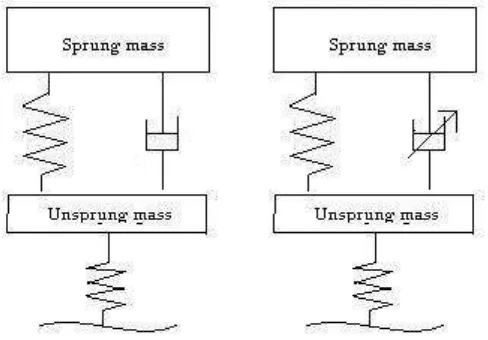
There are three main types of suspension; that is passive, semi-active, and active suspension which depend on the operation mode to improve vehicle ride. Normally, conventional passive suspension is effectively only in a certain frequency range and no on-line feedback action is used. Thus, optimal design performance cannot be achieved when the system and its operating conditions are changed. Passive suspension systems can only temporarily store or dissipate energy at a constant rate and the forces they generate depend on local relative motions. In contrast, active suspensions can be improve the performance of the suspension systems over a wide range of frequency and can adapt to the system variations based on on-line changes of the actuating force. However, active suspensions normally require large power supply, which is the main drawback that prevents this technology from being used extensively in practice.
5 performance to the active system, semi-active suspension is more getting attention compare to active suspension. Semi-active suspension is safer than active suspension because semi-active still can be reacted as passive damper if failure occurred. An undesired force could pull the tire away from road if failure of an active system occurs. Semi-active suspension can be adjusted mechanically or using the rheological properties of the fluid that is used in the damper. There have a solenoid in damper uses to control the damper force.
Some researchers study the controllable suspension performance when control strategy was applied in experiment. The result obtained will compare after that with the passive suspension. Here some result obtained with several performance criteria.
Figure 2.1: Passive suspension Figure 2.2: Semi-active suspension
6
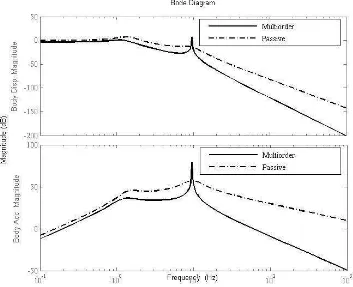
Figure 2.4: Bode plot of body displacement and body acceleration response (Source: Manuscript)
7 Figure 2.4 shows the performance of body displacement and body acceleration for passive suspension and controllable suspension using multiorder PI control. No improvement occurs at low frequency but after 10Hz, multiorder PI control shows the improvement.
Figure 2.5 shows the performance of suspension travel and wheel acceleration. The result obtained is contrast with sprung mass criteria which are the passive suspension shows the improvement at low and medium frequency for suspension travel criteria and medium frequency for wheel acceleration criteria.
2.2 Magnetorheological (MR) Fluid
Magnetorheological (MR) fluid includes into a class of smart fluids whose rheological properties such as elasticity, plasticity, or viscosity change in the presence of a magnetic field. MR fluid consists of a carrier fluid, typically a synthetic or silicone based oil, and ferromagnetic particles (20–50 µm in diameter). Normally MR fluids are free flowing with the consistency of motor oil. In the presence of a magnetic field, however, the particles align and form linear chains parallel to the field. The chains act to restrict fluid movement and solidify the suspension. Many different ceramic, metal and alloy compositions have been described and can be used to prepare MR fluids, as long as the particles used are magnetically multi-domain and exhibit low levels of magnetic coercivity.
8
Figure 2.6: Without Magnetic Field Figure 2.7: Magnetic field applied
There are three modes MR fluid can be used. These modes of operation are referred to as squeeze mode, shear mode and valve mode. A device that uses squeeze mode has a thin film on the order of 0.05cm of MR fluid that is crushed between paramagnetic poles of surface as shown in Figure 2.8.
Figure 2.8: MR fluid used in squeeze mode (Source: James C. Poynor)
Valve mode is the most widely used compared to other modes. MR fluid is used to impede the flow of MR fluid from one reservoir to another as shown in Figure 2.9.
S
9
Figure 2.9: MR Fluid used in valve mode (Source: James C. Poynor)
In shear mode, a thin layer which approximately 0.01cm to 0.04cm MR fluid is sandwiched between two paramagnetic moving surfaces. Shear mode usually useful for dampers that are not required to produce large forces or for brakes and clutches.
Figure 2.10: MR Fluid used in shear mode (Source: James C. Poynor)
2.2.1 Applications of MR fluids
10 considerable effort has gone into development of dampers using MR fluids. The applications of MR fluids that are of interest are related to energy management in automotive applications. In the United States, the automotive industry appears to be actively pursuing development and deployment of MR fluid based devices. MR fluid devices for aerospace applications as well as optical polishing are also emerging.
MR Dampers are not restricted to vehicle applications. Recently, the military has shown interest in using MR Dampers to control gun recoil on Naval gun turrets and on field artillery as shown in Figure 2.11. Another area of study that has incorporated MR dampers is the stabilization of buildings during earthquakes. For application, Lord Corporation has developed a special MR fluid that will never settle out. This increase in commercial interest is largely due to the success of research projects and through the effort of Lord Corporation, which is a leader in the field of MR fluid and devices.
Figure 2.11: Naval gun turret (Source: James C. Poynor)