i
SINGLE BAND TEXTILE ANTENNA
MUHAMMAD ADLY FIZREE BIN SUHOD
This report is submitted in partial fulfillment of the requirements for the award of Bachelor of Electronics Engineering (Wireless Communication) With Honours
Faculty of Electronic and Computer Engineering Universiti Teknikal Malaysia Melaka
v
vi
ACKNOWLEDGEMENT
In the name of ALLAH, I am really thankful and grateful to HIM as I believed in HIM guiding me throughout this project accomplishment.
Firstly, I would love to thank my beloved supervisor, Puan Mawarni Binti Mohamed Yunus, for her great supervision and ideas throughout the process of completing this thesis. In addition, I would like to thank my family and friends for supporting me morally and mentally.
Lastly, I would like to extend my gratitude and thanks to the technicians of Microwave Lab and PSM Lab for helping me in fabricating and measuring process.
vii
ABSTRACT
This project is to design a single band textile antenna which operates at 2.4GHz frequency, which complies with IEEE802.15 (Bluetooth) standards. Since the development of wearable system has opened the possibilities to integrate antennas into clothing, the performance of the antenna is investigated whether it can be applied for Bluetooth applications. Furthermore, the introduction of these textile antennas has revealed the need for wireless communication systems that are unnoticeably integratable into clothing. A textile antenna is proposed to be operated at 2.4GHz for Bluetooth applications. The material of the substrate that has been chosen is fleece which possesses relative permittivity, εr of 1.2548 and thickness of 3.00mm. Copper is used as the radiator which also known as the antenna which has a thickness of 0.35mm. The fleece fabric is chosen because of the εr which is close to 1 and its piled structure that results hydrophobic characteristics. These are great in designing antenna into its optimum performance. The simulation of the design had been carried out by using Microwave CST Studio and the textile antenna had been fabricated. The fabricated antenna had been measured in term of the radiation
viii
ABSTRAK
ix
CONTENTS
CHAPTER TOPIC PAGES
PROJECT TOPIC i
PSM II REPORT STATUS VERIFICATION FORM ii
x
2.4 Antenna Placement 9
2.5 The effect of Relative Permittivity εr of Fabric Material 12
2.6 Fabric Characterization 13
2.7 Previous Work 17
2.7.1 Determination of Dielectric Constant of Fabric Materials and Their Use as Substrates for Design and Development of Antennas for
Wearable Applications [2] 17 2.7.2 A Review of Wearable Antenna [3] 18 2.7.3 Textile Antennas for On-Body Communications:
Techniques and Properties [6] 19 2.7.4 Dual-band Wearable Textile Antenna on an EBG 3.3 The Antenna Design of Single Band Textile Antenna 25
3.4 Calculation 26
3.5 Parametric Study 29
ΙV RESULT
4.1 Antenna Design 30
4.2 Simulation 31
xi
V DISCUSSION AND CONCLUSION
5.1 Discussion 45 5.1 Conclusion 47
xii 2.6 Examples of conductive textile and non-conductive textile 19
2.7 Properties of dielectric, εr of selected materials 21 3.1 The antenna design specifications 25
4.1 The final design parameters from the CST simulation 37
4.2 The final design dimensions and parameters 38
4.3 The setup of antennas 42
xiii
LIST OF FIGURES
NO TITLE PAGES
2.1 Three feeding configurations: coupling feed, microstrip feed
and coaxial feed
6
2.2 Shapes of patch antenna 7
2.3 The layout design of rectangular patch antenna 7 2.4 Typical radiation pattern of rectangular patch antenna 8
2.5 Positioning of the antenna 9
2.6 Possible placement of the antenna on the suit 10 2.7 Antenna is integrated between textile layers 11 2.8 Measurement setup in the anechoic chamber 11
3.1 Flow Chart 23 4.4 Polar plot view of radiation pattern for elevation angle (ɸ=90o) 33 4.5 Surface current of the antenna for 2.4GHz 34
4.6 3D view of radiation pattern for gain 35
xiv 4.12 The setup of Tx and Rx during measuring process 41 4.13 The Horizontal and Vertical Position of Antenna:
(a) Horizontal, (b) Vertical 41
1
CHAPTER I
INTRODUCTION
1.1 Background
2
1.2 Problem Statement
Some people need additional protection against occupational hazards during the professional activities. High performance materials are used to make this special class of clothing. Small and unobtrusive antennas continuously gain in importance in the today’s world of cellular phones and wireless network. Ranges of coverage, directionality and efficiency need to be adjusted and optimized. New fields in this development are textile antennas. Integration of antennas in textiles introduces a bunch of additional design constraints. Compared with conventional antennas, textile antennas possess several advantages such as flexible or bendable textile substrate and have a flat planar structure such that it can be comfortably worn. It possesses smaller size than existed antennas and fully mobile.
1.3 Objectives
The objectives of this project are to design a single band textile antenna operating at 2.4GHz frequency. Secondly, to design and investigatethe performance of such antenna and also designed to be integrated into clothing. And lastly, this project is proposed to operate in 2.4GHz frequency for short range communication application in body and area network such as Bluetooth and WLAN.
1.4 Scope of Work
3
1.5 Thesis Structure
This thesis consists of five chapters. The first chapter represents the overview of single band textile antenna. The objectives of this project have been stated clearly together with the problems statements. Next, the scope of work narrowed the details that need to be focused in this project based on the objectives of this project. Then, the methodology explains briefly about the steps or the flow of project from the early stages to the final stages.
Chapter two consists of the theories and the background study on textile antenna especially in single band textile antenna. This section discusses in detail about the fabric material selection, type of antenna that is going to be implemented and type of feeding techniques together with the textile transmission line. In addition, the last part of this chapter discusses the selected previous works that are really helpful and resourceful in completing this project.
For the third chapter, the details about the methodology are shown clearly from the early stages to the final stages of project. This project started with the literature reviews on the textile antenna especially in material selection aspect followed by the determination of the dielectric permittivity, εr of the fabric. Next, the antenna had been design for 2.4GHz frequency and all the related parameters had been calculated thoroughly. After that, simulation of the designed antenna had been done by using Microwave CST Studio. In order to achieve the design specifications that had been set, parametric study had been performed so that the antenna can be operated to its optimum performances.
4
For the last chapter, which is chapter five consists of discussion and conclusion of this project. Furthermore, the recommendations for future works are also included in this last chapter.
1.6 Project Methodology
5
CHAPTER II
LITERATURE REVIEW
2.1 Introduction
6
Compared with conventional antennas, textile antennas have to fulfill the additional requirement of being drapable. ’Drapability’ means that something can be bent in all directions at the same time. A textile has this property in contrast to standard flexible substrates, which usually have a preferred bending direction. Additionally, in wearable applications, a textile antenna must have a flat and planar structure such that it does not affect wearing comfort.
2.2 Microstrip Antenna
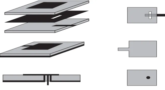
A microstrip antenna which is also known as patch antenna possesses a metal patch on a substrate on a ground plane. There are different types of feeding techniques, they are aperture-coupled, and microstrip feed line and coaxial feed as shown in Figure 2.1.
Figure 2.1: Three Feeding Configurations: Coupling Feed, Microstrip Feed and Coaxial Feed
7
nonplanar surface, simple and cheap. Plus, it is very flexible in terms of resonant frequency, input impedance, radiation pattern and polarization.
Figure 2.2: Shapes of Patch Antenna
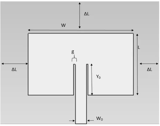
Since the rectangular patch antenna is the most popular among the others, the following part will discuss about rectangular patch antenna. The design layout is as shown in Figure 2.3.
8
All the related parameters in the design can be determined by using the formulae in [3]. The typical radiation pattern of rectangular patch antenna is as shown in Figure 2.4.
Figure 2.4: Typical Radiation Pattern of Rectangular Patch Antenna
2.3 Textile Transmission Line
9
Textile transmission lines built from two variants of fabrics are investigated in this section. The first substrate features wires in warp direction only whereas the second variant embeds wires in warp and weft direction. In the second variant, the cross-running wires will be floating.
2.4 Antenna Placement
The proposed antenna is designed for integration into the outer fire fighter garment. Since this is a multilayer assembly, two types of positioning have to be determined: between what layers and where on the garment. The antenna will be wired to the monitoring system within the garment; therefore it was decided to locate it underneath the moisture barrier and the thermal barrier layer. Underneath the antennas’ ground plane is the inner lining of the garment, as shown in Figure 2.5.
10
The antenna placement on the garment was preferred in the area of the shoulders or the upper arm because of the minimal risk of creasing and wrinkling in these areas.
Figure 2.6: Possible Placement of the Antenna on the Suit
Given the required functionalities, a firefighter garment generally consists of three layers of fabric:
a) An outer shell layer of high-performance material, protecting the firefighter from harsh environmental conditions;
b) A waterproof layer avoiding any passage of water or dangerous liquids c) An insulating layer.