ENERGY HARVESTING BY USING RECTENNA
SUHAIMI BIN MAT DIN
This Report Is Submitted in Partial Fulfillment of Requirements for the Bachelor Degree of Electronic Engineering (Telecommunication Electronics)
Faculty Of Electronic And Computer Engineering Universiti Teknikal Malaysia Melaka
UNIVERSTI TEKNIKAL MALAYSIA MELAKA
FAKULTI KEJURUTERAAN ELEKTRONIK DAN KEJURUTERAAN KOMPUTER
BORANG PENGESAHAN STATUS LAPORAN
PROJEK SARJANA MUDA II
Tajuk Projek : Energy Harvesting By Using Rectenna
Sesi Pengajian : 0 8 / 1 2
Saya SUHAIMI BIN MAT DIN
mengaku membenarkan Laporan Projek Sarjana Muda ini disimpan di Perpustakaan dengan syarat-syarat kegunaan seperti berikut:
1. Laporan adalah hakmilik Universiti Teknikal Malaysia Melaka.
2. Perpustakaan dibenarkan membuat salinan untuk tujuan pengajian sahaja.
3. Perpustakaan dibenarkan membuat salinan laporan ini sebagai bahan pertukaran antara institusi
pengajian tinggi.
4. Sila tandakan ( √ ) :
SULIT*
*(Mengandungi maklumat yang berdarjah keselamatan atau kepentingan Malaysia seperti yang termaktub di dalam AKTA RAHSIA RASMI 1972)
TERHAD** **(Mengandungi maklumat terhad yang telah ditentukan oleh
organisasi/badan di mana penyelidikan dijalankan)
TIDAK TERHAD
Disahkan oleh:
__________________________ ___________________________________
(TANDATANGAN PENULIS) (COP DAN TANDATANGAN PENYELIA)
iii
“I hereby declare that this report is the result of my own work except for quotes as cited in the reference”
Signature :
iv
“I hereby declare that I have read this report and in my opinion this report is Sufficient in terms of the scope and quality for the award of Bachelor of Electronic
Engineering (Telecommunication Electronics) With Honours”
Signature :
Supervisor’s Name: ENGR. NAJMIAH RADIAH BINTI MOHAMAD
v
vi
ACKNOWLEDGEMENT
I am grateful to the Almighty with His grace and guidance that I was able to complete this report.
First and foremost, my utmost gratitude is to Engr. Najmiah Radiah Binti
Mohamad, my project supervisor for his guidance, encouragement, advice and ideas
that have been poured out to me throughout this project.
I also wish to express my appreciation to my friends, Muhammad Farid and Mohd Saufi for sharing the literature and similar research interest and also for their help and encouragement in designing rectenna. I also thank my parents and family for their unceasing encouragement and support throughout my all my studies at University.
vii
ABSTRACT
This thesis describes the original work on designing a rectenna for energy harvesting. Rectenna is the device that uses to capture and convert microwave signal into DC power and it is use as receiving terminal. This project is undertaken as a solution to generate the power without using either electricity or solar because in some places, this two power source is not available due to some limitation. For example in space, even the satellite have solar panel to generate energy, they also can use microwave or radio frequency to generate energy as a backup power. So, the objectives of this project is to study and design a 2.45 GHz rectenna to capture and convert microwave signal into DC power. Generally, rectenna consist of an antenna and rectifying circuit and both of them will determine the overall performance of rectenna. Rectenna was design by using CST microwave studio software and fabricated on FR4 board because the printed rectenna is low cost and easy to manufacture. Measurement experiment is carried on by transmitting different input power by using horn antenna and being measured at different load. Based on the experimental result, the maximum output voltage measure at the load is 0.842 V for
510kΩ resistor and 20 dBm input power. This project is successfully proved that new
viii
ABSTRAK
ix
TABLE OF CONTENT
CHAPTER CONTENTS PAGE
PROJECT TITLE I
REPORT STATUS VERIFICATION Ii
STUDENT’S DECLARATION iii
SUPERVISIOR DECLARATION iv
DEDICATION v
ACKNOWLEDGEMENT vi
ABSTRACT vii
ABSTRAK viii
CONTENT ix
LIST OF FIGURES xii
LIST OF TABLES xiv
LIST OF ABBREVAIATION xv
I INTRODUCTION 1
1.1 Overview Of Rectenna Technology 1
1.2 Objectives 2
1.3 Problems Statement 2
1.4 Project Scope 3
1.5 Methodology 4
1.6 Thesis Outline 4
II LITERATURE REVIEW 6
2.1 Introduction To Energy Harvesting 6
2.2 Energy Harvesting By Using Vibration 6
2.3 Energy Harvesting By Using Magnetic Resonant Frequency 8
x
III THEORETICAL BACKGROUND 12
3.1 Operation of Rectenna 12
3.2 Antenna 13
3.3 Microstrip Patch Design 14
3.4 Microstrip Patch Calculation 15
3.5 Antenna Polarization 16
3.5.1 Linear Polarization 17
3.5.2 Circular Polarization 17
3.5.3 Elliptical Polarization 18
3.6 Advantage And Disadvantages Of Patch Antenna 18
3.7 Rectifier Circuit 18
3.7.1 Half-Wave Rectifier 19
3.7.2 Full-Wave Rectifier 19
3.8 Schottky Diode 20
3.9 Filter 21
3.9.1 Low Pass Filter 22
3.9.2 High Pass Filter 22
3.9.3 Band Pass Filter 23
3.9.4 Band Stop Filter 23
IV METHODOLOGY 24
4.1 Software 24
4.2 Materials 25
4.2.1 FR4 Board 25
4.2.2 Schottky Diode 26
4.2.3 Load (resistor) 26
4.3 Equipment 27
4.3.1 Signal Generator 27
4.3.2 RF Cable 27
4.3.3 Horn Antenna 28
4.3.4 Multimeter 28
4.4 Dimension Of Proposed Antenna 29
4.5 Dimension Of Proposed Rectifier 30
4.5.1 Rectifier With Dual Diode 31
4.6 Project Procedures 31
xi
4.6.2 Rectifier Design Procedure 33
4.6.3 Etching Process Procedure 34
4.6.4 Experiment Setup 35
4.6.5 Measurement Procedure 36
4.7 Overall Budgets 38
V RESULT AND DISCUSSION 39
5.1 Calculation And Simulation Results 39
5.1.1 Antenna Dimension Calculation 39
5.2 Performance Of An Antenna 41
5.3 Rectenna Measurement Results 45
5.3.1 Voltage Received Versus Power Transmit At
Distance 10 cm 45
5.3.2 Voltage Received Versus Power Transmit At
Distance 30 cm 47
5.3.3 Voltage Received Versus Power Transmit At
Distance 60 cm 48
5.3.4 Voltage Received Versus Distance 50
5.4 Analysis Of Rectenna Design 51
VI CONCLUSION AND RECOMMENDATION 53
6.1 Conclusion 53
6.2 Recommendation 54
REFERENCES 55
xii
LIST OF FIGURES
Figure Titles pages
1.1 Block diagram of rectenna design 3
2.1 Schematic of resonant frequency tuneable energy harvesting
device 7
2.2 Spring equivalents for repulsive and attractive forces between
magnets 8
2.3 Wireless energy transfers by using Magnetic resonant frequency 10
2.4 Basic rectenna configurations 10
3.1 Operation of Rectenna 13
3.2 Example of rectenna by using dipole antenna 13
3.3 Example of microstrip antenna 14
3.4 Illustration of microstrip patch antenna 15
3.5 Antenna polarizations 17
3.6 Half-wave rectifier circuits 19
3.7 Full-wave rectifier circuits 20
3.8 Marketed schottky diode 20
3.9 Symbol and equivalent circuit for schottky diode 21
3.10 Frequency response for low pass filter 22
3.11 Frequency response for high pass filter 22
3.12 Frequency response for band pass filter 23
3.13 Frequency response for band stop filter 23
4.1 CST icon 24
4.2 Example of FR4 board 25
4.3 HSMS 2860 surface mount microwave schottky diode 26
xiii
4.5 Signal generator 27
4.6 RF Cable 27
4.7 Horn antenna 28
4.8 Digital millimeter 28
4.9 Antenna dimension for rectenna design 29
4.10 Rectifier dimensions and diode connection 31
4.11 Drawing of FR4 substrate in CST 32
4.12 Drawing of patch antenna on FR4 substrate in CST 32
4.13 Simulation process of square patch antenna 33
4.14 Square patch antennas with rectifier circuit. 34
4.15 Rectenna layouts for etching process 34
4.16 Chemical for etching process (ferric chloride) 35
4.17 Fabricated rectenna 35
4.18 Rectenna measurement setup 36
4.19 Antenna arrangement 37
4.20 Voltage drop before and after ‘ON’ signal generator 37
4.21 Input signal varies with different power 38
5.1 S-parameter magnitude in dB (original design) 41
5.2 S-parameter magnitude in dB (optimize design) 41
5.3 Simulation of current distribution on antenna patch 43
5.4 3D view of radiation pattern 44
5.5 Polar view of radiation pattern 44
5.6 Voltage Received Versus Power Transmit At Distance 10cm 46 5.7 Voltage Received Versus Power Transmit At Distance 30cm 47 5.8 Voltage Received Versus Power Transmit At Distance 60cm 49
5.9 Voltage Received Versus Power Transmit At Distance At Various
xiv
LIST OF TABLES
Table Titles Pages
4.1 FR4 Board Parameter 25
4.2 Dimensions Of Antenna 30
4.3 Dimensions Of Rectifier 31
4.4 Overall Budgets For This Project 38
5.1 Parameter Of Antenna 42
5.2 Measurement Of Voltage Received At Different Load And Different Power Transmit For Distance 10 Cm
45
5.3 Measurement Of Voltage Received At Different Load And Different Power Transmit For Distance 30 Cm
47
5.4 Measurement Of Voltage Received At Different Load And Different Power Transmit For Distance 60 Cm
xv
LIST OF ABBREVIATIONS
AC -Alternating Current
DC -Direct Current
FR4 -Flame Retardant 4
LHC -Left-Handed Circular
PCB -Printed Circuit Board
RHC -Right-Handed Circular
RF -Radio Frequency
RECTENNA -Rectifying Antenna
SPT -Space Solar Power Transmission
UV -Ultra Violet
1
CHAPTER I
INTRODUCTION
This chapter will give an overview about the project as project background, project objective, project scope, project methodology and summary of the project. This chapter will explain briefly about the overall project progress from beginning until the project is complete.
1.1 Overview on Rectenna Technology
2
ground to space and space to space transmission system [1].
The main important part in this project is an antenna. The frequency selected for antenna is 2.45 GHz which means the antenna should be able to operate in that frequency. Frequency 2.45 GHz were selected as operating frequency of this rectenna because the probability to get high efficiency rectenna is high [3] and it unlicensed frequency band. The second part in this project is to design the stub that act as filter to suppress harmonics signal. This part must be design to match the antenna and diode impedance, so that the rectenna could rectify effectively. Then the rectenna will convert the RF energy into DC power by using rectifier circuit. Rectifier circuit is consisting of schottky diode and the load resistor for power measurement. This project will be focusing on the ability of rectenna to convert RF signal to DC power.
1.2 Objectives
The objectives of this project is to study and design a 2.45 GHz rectenna to capture and convert microwave signal into DC power. Another objective is to simulate and fabricate the rectenna for wireless power transmission purpose. This rectenna project will convert the microwave energy into the DC power which is much more useful to run the device. Due to the green technology that highly demands these days, the project seem to be useful in future because it using microwave energy to generate new power and it also can be use as alternative power source in future.
1.3 Problems statement
3
[4]. From another journal, Yu-Jiun Ren and Kai Chang reported that the dual diode rectenna only can provide 76% of conversion efficiency [1]. Hu Hao, Kong Li also reported that, higher rectenna frequency (e.g. 35 GHz) can reduce the aperture area and increase the transmission range but the component to generating that frequency are expensive and inefficient [5].
This project is undertaken as a solution for how to generate the power without using either electricity or solar because in some places, this two power source is not available due to some circumstance. For example in space, even the satellite have solar panel to generate energy, they also can use microwave or radio frequency to generate energy as a backup power. This project also undertaken as a solution for problems reported in related journal about designing good rectenna.
1.4 Project scope
The scope for this project is to find solution to convert the energy from microwave to DC power and to increase the efficiency of power conversion. Rectenna will be used to capture the microwave signal and convert it to DC power.
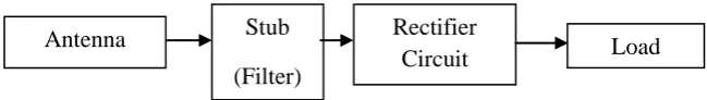
Figure 1.1 Block diagram of rectenna design
The antenna is used to capture the input incoming microwave signal and delivered to rectifier circuit. The rectifying circuit which is consist of stub (filter) and schottky diode is use to change AC microwave signal into a DC signal. The properties of diode will determine the overall performance.
The schottky diode is chosen for rectifying circuit is because that diode has lower built-in voltage that would realize a higher rectifying efficiency [6]. The function of stub (filter) in rectifier circuit is to block any harmonic generated by
Antenna Rectifier
Circuit Stub
(Filter)
4
diode and antenna itself. However, this project is only focus on the output and the capability of rectenna to convert microwave signal into DC power only.
1.5 Methodology
The project is started by selecting the type of antenna use for rectenna design and the operating frequency of an antenna. Then, the matching network and stub (filter) is designed to make sure the antenna is match with the circuit and reject the high order harmonic signal. Lastly, the rectifying circuit is design to convert the microwave signal to DC power.
For the antenna part, the 2.45 GHz microstrip antenna is selected for this project. Microstrip antenna is selected because it is inexpensive and small size. In this project the basic rectangular patch with slot at feeding line is chosen for rectenna configuration. An antenna is design by using CST microwave studio software
For the stub (filter) part, it is designed to pass the frequency of 2.45 GHz. The filter should be able to block higher order harmonic frequency and must match with antenna and rectifying circuit.
For the rectifying circuit, there are two type of diode configuration, the first is single diode configuration which is provide half-wave rectifier and the second is dual diode configuration which provide full-wave rectifier. For this project, dual diode configuration is selected.
1.6 Thesis Outline
5
The first chapter in this report is an introduction. This chapter will give an overview about the project as project background, project objective, project scope, project methodology and summary of the project. This chapter will explain briefly about the overall project progress from beginning until the project is complete.
The second chapter is a literature review. This chapter will discuss about the fact and information from various source before proceed to the project. This part also discuss about the current study of rectenna findings.
The third chapter is theoretical background. This chapter will review about the materials and equipments that will be use in this project. The best techniques and materials will be chosen to implement in this project.
The forth chapter is a methodology where it will describe the methods and techniques that have been used in this project. This chapter will give detail information about the materials, equipment, and experiment procedures that have been used in this project.
The fifth chapter is about result and discussion. This section will explain about the findings of this project and analysis of result. This chapter also explains about the method used to analyze the result.
6
CHAPTER II
LITERATURE REVIEW
This chapter will discuss about the fact and information about energy harvesting from various source before proceed to the project. This part also discuss about the current study of rectenna findings.
2.1 Introduction to Energy Harvesting
Energy harvesting is the process of generating energy from external resources. Energy harvesting devices will convert external resources into electrical energy that much more useful to run the devices. Some systems convert motion into electric energy such as wind turbine, water turbine, ocean waves and many more. Nowadays, there are a lot of new method to harvest the energy have been founded such as by using Vibration energy, magnetic resonant frequency, and microwave.
2.2 Energy Harvesting By Using Vibration
7
general requirement independent of the mechanical to electrical energy transfer mechanism is that the vibration energy harvesting device operates in resonance at the excitation frequency.
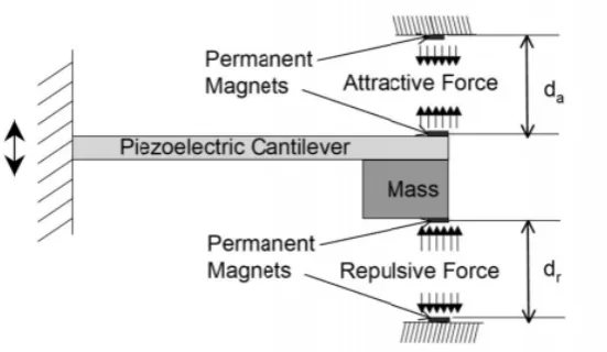
The tuneable energy harvesting device describe here consists of a cantilever beam made up of piezeoelectric material with a tip mass. Four magnets are used to apply attractive and repulsive forces, which are placed on the devices as shown in figure 2.1 [7].
Figure 2.1 Schematic of resonant frequency tuneable energy harvesting device
These magnets apply attractive and repulsive forces at the top and bottom of the cantilever beam and can be readily interchanged. These magnetic forces induce an additional stiffness on the beam which alters the total stiffness of the device and subsequently the resonance frequency. Here the distance between the magnets is varied in order to provide the required magnetic force to tune resonance frequency.
8
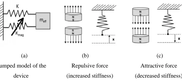
(a) (b) (c)
Lumped model of the device
Repulsive force (increased stiffness)
Attractive force (decreased stiffness)
Figure 2.2 Spring equivalents for repulsive and attractive forces between magnets
2.3 Energy Harvesting By Using Magnetic Resonant Frequency
Magnetic resonant frequency is a wireless energy transfer which is the enable to provide electrical energy to remote objects without wires using oscillating magnetic fields. It is based on strong coupling between electromagnetic resonant objects to transfer energy wirelessly between them.
This differs from other methods like simple induction, microwaves, or air ionization. The system consists of transmitters and receivers that contain magnetic loop antennas critically tuned to the same frequency. Unlike the far field wireless power transmission systems based on traveling electro-magnetic waves, wireless electricity employs near field coupling through magnetic fields similar to those found in transformers except that the primary coil and secondary winding are physically separated, and tuned to resonate to increase their magnetic coupling. These tuned magnetic fields generated by the primary coil can be arranged to interact vigorously with matched secondary windings in distant equipment but far more weakly with any surrounding objects or materials such as radio signals or biological tissue.
strongly-9
coupled resonances for medium range and non-radiative wireless Energy transfer. The scheme which is considered to be non-radiative and anti-jamming could achieve a medium-range wireless energy transfer [8].
They investigated the range and rate of coupling and the interference of extraneous objects in the view of magnetic field coupling. Based on the comparison of two resonant systems, it is discovered that the magnetic near-field in their scheme is non-lossy and the two coils are strongly-coupled. Numerically, it achieved about 60W power transfer between two resonant coils with the distance of 2m. MIT’s investigation mainly focuses on the medium range non-resonant mechanism of wireless energy transfer from the perspective of the magnetic field. However, the adopted method is based on the general physical analysis for resonant coupling objects and purely physical theory, which is unfamiliar to electrical engineers. Furthermore, due to the structure of parasitic parameters resonant coil, it is difficult to determine the capacity of the parasitic capacitance accurately, which is not conducive to the circuit design. In addition, the volume of the coil is slightly larger for general mobile devices [8].