TELKOMNIKA, Vol.15, No.2, June 2017, pp. 786~792
ISSN: 1693-6930, accredited A by DIKTI, Decree No: 58/DIKTI/Kep/2013
DOI: 10.12928/TELKOMNIKA.v15i2.6117 786
Wideband Multi-Port Reflectometer as an Alternative in
Reflection Coefficient Measurement
Rashidah Che Yob, Norhudah Seman*
Wireless Communication Centre (WCC), Faculty of Electrical Engineering, Universiti Teknologi Malaysia, 81310 UTM Johor Bahru, Johor, Malaysia
*Corresponding author, e-mail: huda@fke.utm.my
Abstract
This paper presents the characterization and operation of an alternative device, which is known as multi-port reflectometer to measure the reflection coefficient of any device under test (DUT). Its configuration is formed by two power dividers (D) and four couplers (Q). The characterization is evaluated through the centres of power circles that also known as q-points. Its operation in the reflection coefficient measurement is tested by using three DUTs. The
reflectometer’s good performance and wideband operation are proven between the frequency
band of 1 and 6 GHz via the practical hardware measurement in the laboratory.
Keywords: Coupler, multi-port reflectometer, power divider, reflection coefficient, wideband
Copyright © 2017 Universitas Ahmad Dahlan. All rights reserved.
1. Introduction
The determination of a ratio of two complex signals; one incident and the other one reflected which known as the complex reflection coefficient is required over a specific frequency band in many microwave applications. Particularly, one of the most frequently used as the microwave measurement instruments is a Vector Network Analyzer (VNA), where such task can be performed. Depending on the heterodyning receiver technique, an accurate measurement of the reverse and forward of the scattering parameters of any microwave device under tests (DUTs) is offered by this measurement instrument [1-5]. Unfortunately, this instrument is bulky, very expensive and has limited use in some laboratory environments only [1-5]. Meanwhile, the demand of many applications today requires simple, compact-size and low-cost measurement solution. Therefore, a wideband multi-port reflectometer, which is formed by only passive devices of power dividers (D), and couplers (Q) is proposed to be used in determining the reflection coefficient of the device under test (DUT) as an alternative measurement instrument to the common VNA. Wideband multi-port reflectometer has two input ports provided to a power source and DUT, and also having at least three outputs ports terminated in scalar power detectors. Where, this passive linear circuit can be used to acquire the microwave parameters of voltage, phase, impedance and complex reflection coefficients of active or passive DUT [1-5]. The advantage of the wideband multi-port reflectometer is that it can produce phase characteristic of DUT by only making scalar power measurements, where the requirement of the phase information on the output ports can be ignored.
Furthermore, in its operation; which is opposite to VNA, the frequency down-conversion is not required. Therefore, with this measurement technique of multi-port; the cost of the equipment will be reduced, and the hardware requirements also will be facilitated. Besides that, it has another advantage of lower frequency sensitivity, which not requires frequent calibration that promises long-term stability to the operation [1-5].
2. Design of Multi-Port Reflectometer
(DUT) is connected to Port 2, where it acts as a measurement port. The variable a represents a reflected signal, and the variable b indicates an incident signal to DUT. Meanwhile, the required information on the measurement is obtained from Port 3 to 7, which terminated by five scalar power detectors. Port 3 is used as the reference for the purpose to monitor the power level of the source signal. The constant power level can be maintained through a feedback loop by monitoring the power measured at Port 3. The enclosed broken line part of the wideband multi-port reflectometer in Figure 1 is known as complex ratio measuring unit (CRMU), which also can be known as a correlator [6–7]. The CRMU is the heart of the wideband multi-port reflectometer where it is formed by a power divider and three couplers. It plays a common role similar to the complex ratio detector (CRD) based on the heterodyne receiver technique in the conventional vector network analyzer (VNA) [6–7].
Figure 1. The configuration of the proposed wideband multi-port reflectometer
This multi-port reflectometer is assumed to have power dividers and couplers in ideal operation and identical power detectors that function in the square-law region. Therefore, the reflection coefficient, Г of the DUT for the proposed configuration in Figure 1 can be obtained from the measured power, Piat five output ports is equal to |Vi|
2
, which notation i indicates the port number (i = 3, 4, 5, 6 and 7) using similar mathematical derivations in [1-2]. The
corresponding representation of Г also can be determined from the known scattering
parameters of the wideband multi-port reflectometer as in following Equation (1):
(1)
Corresponding to the Port 4 to 7, the output voltage, Vi can be written in the form of reflection coefficient ( ), incident signal (b) and centre of the power circle or known as q-points as expressed in (2) [2]:
(2)
where, | -qi| presents the radius of power circle. Alternatively, Vi can be computed from the input
voltage (Vo), transmission coefficient (Sij) and reflection coefficient (Г) as expressed in (3) [2].
Notation j is referring to 1 and 2.
(3)
From Equation (3), the reflection coefficient (Г) can be rewritten to expression (4) [2]:
ISSN: 1693-6930 788
Meanwhile, the following Equation (5) is used to determine the value at the centre of power circle (q-points) as presented in [2] and [8]:
(5)
As ideal components are assumed to be used in the construction of the multi-port reflectometer, the parameter S22 in equation (5) is very close to zero. Hence, Equation (5) can
be simplified to (6):
Equation (8), four circles can be defined. In a graphical form, the reflection coefficient, of any DUT can be presented by the intersection of these power circles [2, 8]. More output ports can significantly improve the multi-port reflectometer performance and make it less sensitive to power measurement errors by having more power circles [2, 8]. However, the accuracy improvement does not ordinarily warrant additional complexity.
3. Measurement
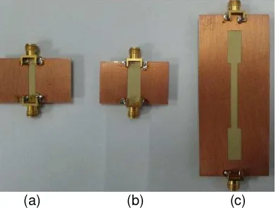
In this paper, theproposed wideband multi-port reflectometer configuration is formed by using the commercially available components, which are Krytar 90º hybrid coupler and Aeroflex two-way in-phase power divider as illustrated in Figure 2 (a) and (b). While, the shown cable in Figure 2 (c) is used to connect the couplers and power dividers. The investigation of the characterization and operation of wideband multi-port reflectometer is conducted in the laboratory. Figure 3 represents the photograph of the proposed multi-port reflectometer setup that is performed in the laboratory.
TELKOMNIKA ISSN: 1693-6930 789
Figure 2. The components used to form the proposed wideband multi-port reflectometer: (a) Krytar 90º hybrid coupler (b) Aeroflex two-way in-phase power divider and (c) cable.
Figure 3. The measurement setup of the proposed multi-port reflectometer
(a) (b) (c) (a) (b) (c)
Figure 4. Photograph of the top view of three DUTs: (a) unknown load #1 (b) unknown load
#2 and (c) unknown load #3
Figure 5. Photograph of the bottom view of three DUTs: (a) unknown load #1 (b) unknown
load #2 and (c) unknown load #3
4. The Characterization and Operation of Wideband Multi-Port Reflectometer
The transmission coefficients of the proposed reflectometer, which fixed as in Figure 3 are approximately around -12 dB ± 3 dB. While, the return losses of the wideband multi-port reflectometer are observed at Port 1 and Port 2. Referring to the concerned operating frequency
band, which is from 1 to 6 GHz, the Port 1’s return loss is better than 20 dB. Whilst, the return
loss at Port 2 is finer than at Port 1 for the similar operating frequency band, which is greater than 22 dB. Meanwhile, the referenced phase values of the transmission coefficients against the phase of S41 and S42 stay roughly around 0°, 90° and -90° over the designated frequency band.
By having this information of transmission coefficients and phases, the characteristics of the centre of the power circles (q-points) are identified in purpose to have a good wideband performance of the multi-port reflectometer. To determine the q-points (qi), where i = 4, 5, 6 and
r 90º
Coupler (Q)
Power Divider (D) VNA
Cable
CRMU
ISSN: 1693-6930 790
7; the information on the transmission coefficients referenced to Port 1 (Si1), and Port 2 (Si2) are
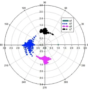
applied to equation (6). The results of the q-points are presented in constellation form or also known as the polar plane in Figure 6. The point q4 is assumed as the reference point, and it is
located at a fix ideal position of 1, and the other remaining points are relative to the point q4. The
remaining q-points are located 90° of the angular separations. Referring to Figure 6, the magnitude of the q-points are approximately around 1 ± 0.5 over the frequency band between 1 and 6 GHz. Followed by the phase characteristics of q4 to q7, which are approximately around
0°, -180°, -90° and 90°, respectively.
Figure 6. Polar plot (constellation) of the centre of power circle (q-point) of the proposed wideband multi-port reflectometer
Figure 7. Magnitude of q3 of the proposed wideband multi-port reflectometer.
In the investigation of the q-points, there is one remaining criterion that needs to be verified, which is the magnitude of the q3. This criterion concern the condition of |q3| > 1 and |qi|
< |q3|, where i = 4, 5, 6 and 7. The obtained measured result from the magnitude of the q3 is
plotted in Figure 7. As seen in Figure 7, the values of the |q3| are greater than 4 over the
frequency band of 1 to 6 GHz. Therefore, the measurement results of the |q3| are meeting the
requirement of the stated conditions, which are |q3| > 1 and |qi| < |q3|. The next concern is to
(a) (b)
(c)
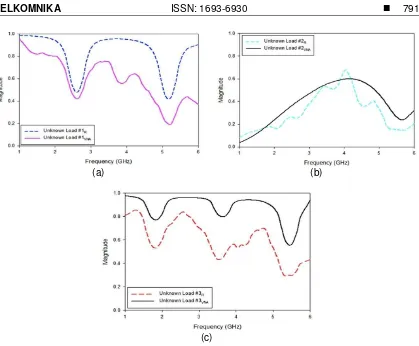
Figure 8. The measured reflection coefficients (Г) for (a) unknown load #1, (b) unknown load #2 and (c) unknown load #3 using the proposed wideband multi-port reflectometer (R) and VNA
As seen in Figure 8(a), for unknown load #1, the magnitude of the complex reflection
coefficients (Г) from VNA is approximately at 1 with two slopes in regard to lowest measured
result around 0.5 ± 0.05 at 2.5 and 5.2 GHz. While for the measured result obtained by using the proposed wideband multi-port reflectometer, |Г| has similar pattern with lower magnitude. The two slope patterns are noticed at similar frequency points.
Then, when DUT is in the form of unknown load #2, as point out in Figure 8 (b); the
obtained |Г| by using VNA is initially at 0 and it increases up to 0.55 at 4 GHz. Henceforth, |Г| is
decreased gradually with lowest value of 0.22 at 5.7 GHz. Then, it increases to 0.3 at 6 GHz.
Whilst, the measured |Г| of unknown load #2 from the proposed wideband multi-port reflectometer shows non-linear progression and reduction across the designated frequency range but following similar pattern with slightly different magnitude. Meanwhile, for the case of
unknown load #3; the measured |Г| from VNA demonstrates three lumps with highest values
close to 0.9. Three slopes can be noticed at 1.8, 3.8 and 5.5 GHz with the measured |Г| of 0.8, 0.8 and 0.5, accordingly. While, |Г| that measured by the proposed wideband multi-port reflectometer shows identical trend with lower magnitude.
ISSN: 1693-6930 792
5. Conclusion
The characterization and operation of the wideband multi-port reflectometer have been observed through the centre of power circle (q-points) and the magnitude of the complex reflection coefficient by implementing commercially available hardware measurement in the laboratory, which are Krytar 90º hybrid coupler and Aeroflex two-way in-phase power divider over the wideband frequency band of 1 to 6 GHz. The analysis on the characteristics and operation of the wideband multi-port reflectometer represents the performance of the proposed device. Based on the measurement results that have been obtained, it can be stated that this multi-port reflectometer has offered a good wideband performance compared to narrower performance shown by [5] and [10]. Even though [1-2], [4, 8] exhibited very wide performance, however [2] and [8] only considered reflectometer characteritics, while [1] and [4] demonstrated simulated operation without experimental results. Nevertheless, the performance of the proposed wideband multi-port reflectometer still can be improved in future investigations by applying a suitable error correction procedure. This is due to the presented wideband multi-port reflectometer is not operating in error-free state condition. By applying the suitable error correction procedure; the imperfect characterization of the wideband multi-port reflectometer will be removed, and an accurate reflection coefficient measurement can be performed.
References
[1] Bialkowski ME, Seman N, Leong MS, Yeo SP. Fully integrated microwave reflectometer in multi-layer
microstrip-slot technology for ultra wideband applications. 2008 17th International Conference on Microwaves, Radar and Wireless Communications, MIKON. 2008.
[2] Seman N, Bialkowski ME. Design of a UWB Microwave reflectometer with the use of a microstrip-slot
technique. Microwave Opt Technol Lett. 2009; 51(9): 2169-2175.
[3] Hoer CA. A network analyzer incorporating two six-port reflectometers. IEEE Trans Microwave
Theory Tech. 1977; 25(12): 1070-1074.
[4] Seman N, Bialkowski ME. Design of a UWB 6-port reflectometer formed by microstrip-slot couplers
for use in a microwave breast cancer detection system. IEEE Antennas and Propagation Society, AP-S International AP-Symposium (Digest). 2007.
[5] Yob RC, Seman N. Wideband multi-port reflectometer in microstrip planar technology for microwave
imaging application. 2012 IEEE Asia-Pacific Conference on Applied Electromagnetics, APACE 2012 - Proceedings. 2012.
[6] Bialkowski ME, Abbosh AM, Swayn J. Design of a compact microwave six-port vector voltmeter for
UWB applications. IEEE MTT-S International Microwave Symposium Digest. 2007.
[7] Bialkowski ME, Abbosh AM, Seman N. Compact microwave six-port vector voltmeters for
ultra-wideband applications. IEEE Trans Microwave Theory Tech. 2007; 55(10): 2216-2223.