NORMAL MODE ANALYSIS OF AN EXHAUST PIPE
MOHAMMAD QAYYUM B. A.SHUKOR
This report is submitted to Faculty of Mechanical Engineering in partial fulfill of the requirement of the award of Bachelor’s Degree of Mechanical Engineering
(Automotive)
Faculty of Mechanical Engineering
UNIVERSITI TEKNIKAL MALAYSIA MELAKA
“I hereby verify that I have read this report and I find it sufficient in term of quality and scope to be awarded with the Bachelor Degree in Mechanical Engineering “
Signature : ………
Supervisor Name : ………
“I hereby to declare that the work is my own except for summaries and quotations which have been duly acknowledge”
Signature : ……….
Author : MOHAMMAD QAYYUM B. A.SHUKOR
DEDICATION
To him who is our source of grace, our source of commitment, and our source of knowledge,
And,
ACKNOWLEDGEMENT
All praises to the Almighty Allah, for giving me the strength, patience and guidance throughout the process of completing this investigation. I am grateful to have the morally and physically support from many people throughout completing this study. For this opportunity, I would love to thank whose are either directly or indirectly involved during the process of this research is conducted.
Most immediately, I would like to express my very special gratitude and appreciation to my supervisor, Mr. Faizul Akmar Abdul Kadir for his valuable suggestion, comments and advice in every stage of this project. All the discussion makes me understand every detailed in this road vehicle aerodynamic analysis. My token of appreciation also goes to all the lecturers from Faculty of Mechanical Engineering especially from Automotive Department for being very nice and making this study easier to be completed.
ABSTRACT
ABSTRAK
iv
TABLE OF CONTENT
CHAPTER CONTENT PAGE
ACKNOWLEDGEMENT i
ABSTRACT ii
ABSTRAK iii
TABLE OF CONTENT iv
LIST OF FIGURE vii
NOMENCLATURE x
CHAPTER I INTRODUCTION
1.1 Project Overview 1
1.2 Problem Statement 2
1.3 Objective 2
1.4 Scope of Study 2
1.5 Expected Outcome 3
CHAPTER II LITERATURE REVIEW
2.1 Introduction 4
2.2 Exhaust System 4
2.2.1 Exhaust System Overview 4 2.2.2 Exhaust Connections 6 2.2.3 Exhaust with Extractors 7
2.3 Vibration 8
2.3.2 Free Vibration without Damping 10 2.3.4 The System to Vibrate Factor under
No Force 11
2.3.5 Free Vibration with Damping 12 2.3.6 Force Vibration with Damping 15
2.4 Modal Testing and Analysis 19
2.4.1 Modal Testing and Analysis Overview 19
2.4.2 Modal Domain 21
CHAPTER III METHODOLOGY
3.1 Introduction 24
3.2 Literature Review 26
3.3 Method Of Testing 26
3.4 Experimental Method 26
3.4.1 Preparing the Exhaust Pipe 26
3.4.2 Preparing the Rig 27
3.4.3 Experimental Procedures 28
3.5 Software Simulation 35
3.5.1 Coordinate Measuring Machine 35
3.5.2 CATIA V5R10 Software 36
3.5.2 MSC Nastran Software 38
3.6 Results And Data Analysis 42
3.6.1 Experimental Results 42 3.6.2 Simulation Results 42
3.7 Correlation 42
vi
CHAPTER IV RESULTS AND DISCUSSIONS
4.1 Introdction 44
4.2 Experimental Results 45
4.2.1 First Mode Shape of An Exhaust Pipe 47 4.2.2 Second Mode Shape of An Exhaust Pipe 48 4.2.3 Third Mode Shape of An Exhaust Pipe 49 4.2.4 Fourth Mode Shape of An Exhaust Pipe 50 4.2.5 Fifth Mode Shape of An Exhaust Pipe 51
4.3 Simulation Results 52
4.4 Correlation between Experimental Results
And Simulation Results 57
4.5 Appropriate Mounting Point Location 58
4.5 Discussion 59
4.5.1 Expermental Results 59
4.5.2 Simulation Results 60
CHAPTER V CONCLUSION
5.1 Conclousion 61
5.2 Recommendation 62
LIST OF FIGURE
NO TITLE PAGE
2.1 Exhaust system components 5
2.2 Components of an exhaust system 5
2.3 Joint on mufflers and exhaust pipe 6
2.4 Exhaust manifold to engine pipe connection 6
2.5 Semiflexible connection in exhaust system 7
2.6 Exhaust manifold with extractor pipes; the inlet manifold has water heating 8
2.7 Free body diagram of free vibration without damping 10
2.8 Free body diagram of free vibration with damping 12
2.9 Figure of frequency of vibrations 14
2.10 Figure of frequency ratio versus amplitude 17
2.11 A cantelever beam exhibits distinct vibration deformation patterns. Each deformation pattern, called a mode shape, behaves like a SDOF component. The measured FRF (upper right corner), X2/F1, is understood as a superposition of the SDOF FRF's. 19 2.12 Vibration response of a SDOF system to two different excitation processes. The upper diagram shows response to an applied sine sweep forcing function. The lower diagram shows response to a hammer impact force. 20
2.13 Mode shapes of a simply supported beam 21
viii 2.15 The first mode shape of the tuning fork has the base fixed and the
maximum deflection at the end; the second mode shape has the
ends fixed and maximum deflection at the middle. 23
3.1 Flow Chart of Project Implementation 25
3.2 Components of an exhaust pipe 27
3.3 Rig (isometric view) 27
3.4 Data points labeled on the exhaust pipe 28 3.5 Figure of impact hammer Impact hammer instrumented
with a load cell to measure the excitation force and different
hardness tips. 29
3.6 DEWESoft program setup 30
3.7 DEWESoft program setup for accelerometer scaling 31 3.8 DEWESoft program setup for impact hammer scaling 31 3.9 DEWESoft measuring setup for performing the FRF spectrum 32
3.10 Impact hammer test set up 33
3.11 Start hitting to perform FRF in the program 34
3.12 Example of FRF that can be obtained using DEWESoft program 34 3.13 Modeling exhaust pipe by using CATIA V5R10 software 36 3.14 Exhaust pipe drawing in the CATIA V5R10 software 37 3.15 Exhaust pipe dimension in the CATIA V5R10 software 37
3.16 Meshing process 39
3.17 Material properties details from CATIA V5R10 software
(Stainless Steel) 39
3.18 Parameter input data before simulation analysis 40 3.19 Parameter input data before simulation analysis (continue) 40 3.20 Selected subcases and file before simulation analysis 41 3.21 Running normal modes simulation to the geometry of an
exhaust pipe 41
4.1 Results of Frequency Response Function (FRF)
spectrum of point 1 45
4.3 First mode shape of an exhaust pipe followed by
point at 34.18Hz 47
4.4 Second mode shape of an exhaust pipe followed by
point at 83.01Hz 48
4.5 Third mode shape of an exhaust pipe followed by
point at 175.78Hz 49
4.6 Fourth mode shape of an exhaust pipe followed by
point at 244.14Hz 50
4.7 Fifth mode shape of an exhaust pipe followed by
point at 52.46Hz 51
4.8 Normal mode analysis for first harmonic frequency of an
exhaust pipe 52
4.9 Normal mode analysis for second harmonic frequency of
an exhaust pipe 53
4.10 Normal mode analysis for third harmonic frequency of
an exhaust pipe 54
4.11 Normal mode analysis for fourth harmonic frequency of
an exhaust pipe 55
4.12 Normal mode analysis for fifth harmonic frequency of
an exhaust pipe 56
4.13 Experimental and simulation analysis natural frequencies 57
x
NOMENCLATURE
UTeM – Universiti Teknikal Kebangsaan Malaysia, Melaka PSM – Projek Sarjana Muda
FFT – Fast Fourier Transform
FRF – Frequency Response Function CMM – Coordinate Measuring Machine dB – Decibel (units)
DAQ – Data Acquisition System
CHAPTER I
INTRODUCTION
1.1Project Overview
The improvement of simulations tools has been helping the automotive industry and other areas over the last few years. The solution of some design issues, when done with the help of simulation software, can be achieved with significant time and cost savings.
In order to figure out the modes of the exhaust pipe, there are several experiments that can be used to determine it. One of them is an impact hammer test. Impact testing is a simple and fast technique for obtaining good approximations of a systems modal properties and frequency response information.
Unfortunately, the experiment tests are time consuming. The most convenient way to improve design is the simulation-based methods using the software. There is a lot of software that can be used to determine normal mode frequencies which cause vibration. One of the software that is currently used to define the mode shape is by using MSC Nastran. However, difficulties still exist in FEA based methods in simulating the exact vibration response of exhaust systems.
2
1.2Problem Statement
The problem which always came up from the driver of the passenger car is the vibration at the car body. This vibration is usually come from many sources such as from wheels and tires, suspensions, engine’s mounting, air-conditioning compressor and also exhaust pipe. Thus, to reduce the vibration at the car’s body, we can reduce it by preventing the vibration at exhaust pipe itself as one of the solution.
To reduce the vibration that occurs to the exhaust pipe system, the characteristic of an exhaust pipe system must be studied first. One of the characteristic that influence the vibration is natural frequencies of an exhaust pipe system. As a solution, the normal modes analysis by using several methods must be done to study the relation of it to the vibration that occurs to the exhaust pipe system.
1.3 Objective
The objectives of this project are:
To do normal mode analysis at vehicle’s exhaust pipe.
To search an appropriate mounting point at exhaust pipe.
To study and improve the design of exhaust pipe mounting.
1.4 Scope of Study
The scopes of this project are:
Study the vibration of exhaust pipe for Proton Wira 1.6L variant.
Obtain the normal mode or frequency of exhaust pipe using the MSC Nastran software for the simulation.
1.5Expected Outcome
At the end of the research as expected, the natural frequencies of an exhaust pipe can be known by using the Impact Hammer Test and normal modes analysis of an exhaust pipe can be obtained by using MSC Nastran Software simulation. From this experimental and simulation results, the correlation between it can be achieved.
4
CHAPTER II
LITERATURE REVIEW
2.1 Introduction
The literature review is based on the physics of the project undertaken here, concentrating on the introduction on the exhaust system, normal mode analysis and vibration theory. The literature review continues with the discussion on the information related with how to conduct the experiment and software simulation for this research.
2.2 Exhaust System
2.2.1 Exhaust System Overview
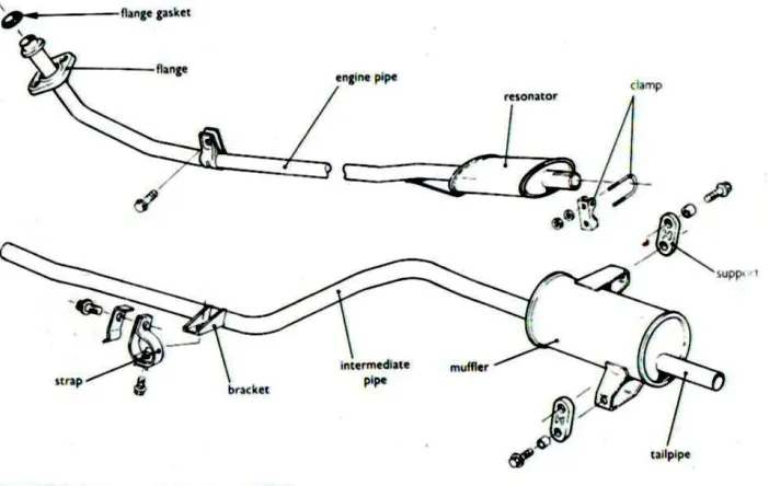
The parts of an exhaust system are shown in Figure 2.1. The main parts are the engine pipe, resonator, intermediate pipe, muffler and the tailpipe. The engine pipe is attached to the exhaust manifold outlet by the flange. Brackets and mountings on the various parts support the system in relation to the engine and the body of the vehicle.
The exhaust system has flexible mountings that prevent exhaust vibration from being transmitted to the body. They also allow for thermal expansion of the system.
with separate branches joined to a flange. Twin engine pipes are used between the manifold and the intermediate pipe. Two mufflers are fitted, one in the middle and the other at the rear end of the system.
Figure 2.1 : Exhaust system components Source : [1]
6
2.2.2 Exhaust Connections
In some cases, the exhaust pipes and mufflers are joined by fitting the end of one pipe into another which shown in Figure 2.3. A clamp is then used to hold the parts firmly together. In other cases, connections between the parts of the system are made with flanged joints.
Figure 2.3 : Joint on mufflers and exhaust pipe Source : [1]
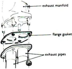
Figure 2.4 shows a joint between the exhaust manifold flange and the engine pipe flange. Two holes in the manifold flange align with the two corresponding holes in the engine pipes. The exhaust gas from two of the engine’s cylinders is fed into each engine pipe. A gasket of heat-resistant material is fitted between the two flanges.
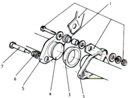
Figure 2.5 shows one type of connection that is used between the engine pipe and the intermediate pipe. This is semi flexible designs that assist with alignments of the pipes and also helps to reduce vibrations. In this joint, the sealing ring (3) between the two pipes has a spherical end, which fits into a similarly shaped end of the exhaust pipe (4). The two bolts (7) that hold the flanges (2) and (5) of the two pipes together are fitted with springs (6), so that the sealing ring is held firmly onto its seat. This provides a joint that is firm, but not rigid.
Figure 2.5 : Semiflexible connection in exhaust system
1 mounting-bracket assembly, 2 flange on engine pipe, 3 sealing ring, 4 conical seat, 5 flange on intermediate pipe, 6 spring, 7 flange bolt Source: [1]
2.2.3 Exhaust with Extractors
8
Figure 2.6 : Exhaust manifold with extractor pipes; the inlet manifold has water heating Source : [1]
2.3 Vibration
2.3.1 Vibration Overview
Vibration is a study of the repetitive motion of objects relative to a stationary frame of reference or nominal position (usually equilibrium). The vibrational properties of engineering devices are often limiting factors in their performance. Vibration can either be harmful and should be avoided, or it can be extremely useful and desired.
Typical examples of vibration familiar to most are the motion of a guitar string, the quality of ride of an automobile and motorcycle, the motion of an airplane’s wings, and the swaying of a large building due to wind or earthquake. Vibration is modeled mathematically based on fundamental principles such as Newton’s laws, and analyzed using mathematical methods.
The physical explanation of the phenomena of vibrations concerns the interplay between potential energy and kinetic energy. A vibrating system must have a component that stores potential energy and releases it as kinetic energy in the form of motion (vibration) of a mass. The motion of the mass then gives up kinetic energy to the potential-energy storing device. Vibration can occur in many directions and can be the result of the interaction of many objects.
the motion of a tuning fork, the reed in a woodwind instrument or harmonica, or the cone of a loudspeaker is desirable vibration, necessary for the correct functioning of the various devices.
More often, vibration is undesirable, wasting energy and creating unwanted sound-noise. For example, the motions of engines, electric motors, or any mechanical device in operation are usually unwanted vibrations. Such vibrations can be caused by imbalances in the rotating parts, uneven friction, the meshing of gear teeth, and etcetra. Careful designs usually minimise unwanted vibrations. The study of sound and vibration are closely related. Sound, pressure waves are generated by vibrating structures and pressure waves can generate vibration of structures. Hence, when trying to reduce noise it is often a problem in trying to reduce vibration.
2.3.2 Types of Vibration
Free vibration occurs when a mechanical system is set off with an initial input and then allowed to vibrate freely. Examples of this type of vibration are pulling a child back on a swing and then letting go or hitting a tuning fork and letting it ring. The mechanical system will then vibrate at one or more of its natural frequencies and damp down to zero.
10
2.3.3 Free Vibration without Damping
Figure 2.7 : Free body diagram of free vibration without damping Source :[3]
To start the investigation of the mass-spring-damper, the damping is negligible and that there is no external force applied to the mass (free vibration) will be assumed. The force applied to the mass by the spring is proportional to the amount the spring is stretched "x" (the spring is already compressed due to the weight of the mass will be assumed). The proportionality constant, k, is the stiffness of the spring and has units of force/distance (e.g. lbf/in or N/m).
The force generated by the mass is proportional to the acceleration of the mass as given by Newton’s second law of motion.
The sum of the forces on the mass then generates this ordinary differential equation: