REMOTE TERMINAL UNIT (RTU) BASED ON ELECTRICAL LOAD CONTROLLER
MOHD NUR YASSIEEN BIN MAT ZAKI B010410139
“I hereby declare that I have read through this report and found that it has comply the partial fulfillment for awarding the degree of Bachelor of Electrical Engineering
(Industrial Power)”
Signature : ………
Supervisor’s Name : DR. MUSSE MOHAMUD AHMED
REMOTE TERMINAL UNIT (RTU) BASED ON ELECTRICAL LOAD CONTROLLER
MOHD NUR YASSIEEN BIN MAT ZAKI
This Report Is submitted In Partial Fulfillment Of Requirement For The Degree of Bachelor In Electrical Engineering (Industrial Power)
Fakulti Kejuruteraan Elektrik Universiti Teknikal Malaysia Melaka
“ I hereby declare that this report is a result of my own work except for the experts that have been cited clearly in the reference.”
Signature : ………
Name : MOHD NUR YASSIEEN BIN MAT ZAKI
Date : ………
TABLE OF CONTENTS
CHAPTER CONTENT
PAGE
ACKNOWLEDGEMENT i
ABSTRACT
ii-iii
LIST OF FIGURES iv
LIST OF APPENDIX v
I INTRODUCTION 1
1.1 Overview 1
1.2 Project Objectives 2
1.3 Problem Statement 2
1.4 Scope of Project 2
II LITERATURE REVIEW 3
2.1 General 3
2.2 RTU and Supporting Equipment Description 5
2.3 RTU versus PLC 8
2.4 RTU Interconnection 9
2.5 Interfacing RTU and SCADA 10
2.6.1 ISaGRAF Workbench 11
2.6.2 Quick LD Editor 12
2.6.2.1 Using the Quick LD editor 12
2.6.2.2 Basics of the LD language 12-13
2.6.3 FBD Editor 14
2.6.3.1 Using the FBD/LD editor 14
2.6.3.2 Basics of the FBD/LD languages 14-15
2.6.4 SFC Editor 16
2.6.4.1 Using the SFC editor 16
2.6.4.2 SFC language main topics 16
2.6.5 Structured Text Editor 17
2.6.5.1 ST main syntax 18
2.6.5.2 Expression and parentheses 19
2.6.6 Instruction List Editor 19
2.6.6.1 Instruction List main syntax 19-20
2.6.7 Flow Chart Editor 21
2.6.7.1 Using the Flow Chart editor 21 2.6.7.2 Basics of the FC language
21-22
III PROJECT METHODOLOGY
23 3.1 Project Methodology 23-24
3.2 Project Flow Chart 25
IV RESULTS AND DISCUSSIONS
4.1 Results 26-33
4.2 Discussion 34
V CONCLUSION 35
5.1 Results 35
5.2 Conclusion 35
ACKNOWLEDGEMENT
First of all, I would like to thank Allah, who has given me a chance and strength to complete my Projek Sarjana Muda 2 and my report. I would like to thank Universiti Teknikal Malaysia Melaka (UTeM) especially Faculty of Electrical Engineering(FKE) for giving me an opportunity to do my Projek Sarjana Muda 2(PSM 2) in fulfillment for Bachelor of Electrical Engineering.
Then, I would to thank my supervisor, Dr. Musse Mohamud Ahmed for supervising me in this project and giving me full support and teach me whatever i did not know. Without him, I cannot obtain more knowledge about Remote Terminal Unit and complete this project. The knowledge that I acquired about this Remote terminal Unit is precious because as an electrical power student, I did not take this subject and it maybe useful when I go through the working environment
ABSTRACT
ABSTRAK
Projek ini adalah projek mereka bentuk dan membangunkan RTU
LIST OF FIGURES
CHAPTER CONTENT PAGE
2.0 LITERATURE REVIEW
Figure 2.1: Remote terminal unit in distribution panel box 8 Figure 2.2: Interfaced system between RTU and SCADA 10
Figure 2.3: ISaGRAF Workbench 22
4.0 RESULTS AND DISCUSSION
Figure 4.1: Remote terminal unit model I_7188XG 26 Figure 4.2: Specifications of RTU model I_7188XG 27
Figure 4.3: Reset button from RESET button 28
Figure 4.4: counter ladder diagrams 29
Figure 4.5: Mode ladder diagram 30
LIST OF APPENDIXS
NO CONTENT PAGE
A Project’s Planning Schedule 37
CHAPTER I
INTRODUCTION
REMOTE TERMINAL UNIT (RTU) BASED ON ELECTRICAL LOAD CONTROLLER
1.1 Overviews
1.2 Project Objectives
• To program the RTU as the controller that can operate, control, and monitor electrical distribution system automatically.
• To Interface Remote Terminal Unit (RTU) with SCADA.
• To run the distribution and the connected system automatically
1.3 Problem Statement
Normal and ordinary electrical apparatus and equipment use conventional operation and control means to function. Automated electrical apparatus and equipment such as automated distribution panels need to use RTU and SCADA. This project will use RTU as a controller to operate, monitor and control the electrical distribution system and the connected load.
1.4 Scope of Project
CHAPTER II
LITERATURE REVIEW
2.1General
Remote terminal units (RTU) collect data automatically and connect directly to the sensors, meters, loggers or process equipment. They serve as slave units to supervisory controllers or supervisory control and data acquisition (SCADA) masters. Remote terminal units are located near the monitored process and transfer data to the controller unit on command. They often include integral software, data logging capabilities, a real-time clock (RTC) or totalizer, and a battery backup. Intrinsically safe remote terminal units are designed to operate safely in hazardous environments. Devices with weather tight enclosures are designed to prevent the moisture, dust or other environmental contaminants. Closed loop systems use proportional, integral and derivative (PID) control; proportional and integral (PI) control; proportional and derivative (PD) control; or proportional (P) control. Redundant RTUs are complete remote terminal units that contain all of the transceivers, encoders, and processors needed for proper functioning in the event that a primary RTU stops working. [2]
Important specifications for remote terminal units (RTUs) include
long distances. Web-enabled RTUs use the Internet for communications. Programmable logic controllers (PLC) can be used as stand-alone devices or in conjunction with a SCADA or other control systems. In terms of ports, most manufacturers specify the number of analog or digital input/output (I/O) ports. Memory size is usually measured in megabytes (Mb). [3]
Remote terminal units differ in terms of features. Devices that include alarms, buzzers, or visual indicators such as blinking lights alert operators about various conditions. Auto-dialing RTUs automatically call a non-dedicated phone number whenever data needs to be transferred. Differential inputs eliminate electrical noise from small amplitude signals. Isolated inputs convert electrical signal inputs into optical signals which are then converted back to electrical signals. Remote terminal units with an expansion card provide additional data storage or processing power. Devices that are designed for environmental monitoring check weather conditions or indoor air quality. Some remote terminal units are suitable for indoor use and mount in standard 19” telecommunications racks. [1]Others are designed for process monitoring in applications such as oil field exploration.
The RTU shall interface to existing data acquisition systems or other field instrumentations, and shall gather and store data, and facilitate telecommunication with the Central Station Computer.
b. Environment:
i. Logical Environment:
The signal chain includes the process equipment, sensing devices, data acquisition system, RTU, modem,
communications link and Central Station. ii. Physical Environment:
Typical environments shall include "friendly" and "Central Station" environments. Friendly environments include clean, air conditioned areas such as computer rooms and offices. [4]Hostile environments may include exterior spaces or interior spaces without benefit of air conditioning, and areas where free floating air particulates may impede the normal operation of exposed electronics. Each RTU shall be mounted in such a manner as to be environmentally qualified.
iii. Electrical Environment:
1) Connected Devices:
shall make its data available to local and Central Stations.
2) Sensor-based Data to be acquired:
Where applicable, the RTU shall be able to directly monitor transducers which sense variables required for compliance determinations. At a minimum, input analog conversion hardware should operate with a medium level of resolution (i.e. 12 bit resolution) and a sampling rate sufficient to accurately characterize the sensor based data.[2]
iv. Description of Data to be transmitted:
All data shall be made available at data output ports in ASCII format as described below:
1) Data Sampling:
2) Rule-specific Data Sets c. Functions:
The RTU shall provide the following functions: i. Power-Up/Restart Mode:
Upon resumption of power after a loss, the RTU shall
automatically restart and reset itself to predetermined system settings.
ii. Non-Communicating Mode:
transactions for later communications with the Central Station.
iii. Failure Mode:
In the event the RTU is unable to initiate communications with the Central Station, the RTU shall perform the following actions:
1) The RTU shall first make four subsequent attempts to establish communications with the Central Station. 2) Upon failure of the fourth attempt, the RTU shall:
a. Revert to the non-communicating mode for a period of fifteen (15) minutes and then again attempt to establish communications with the Central Station.
b. Each failure shall result in the execution of the failure mode sequence.
3) Error Tolerance:
The RTU shall perform its specified functions without misinterpretation of input information, errors in output signals, damage to internal components, and loss or change of stored information with either common mode to ground or differential mode transients present on the communication ports, circuits or power sources which shall be connected to the inputs and power supply terminals to the equipment.
The RTU (Remote Terminal Unit) is a ruggedized computer with very good radio interfacing. It is used in situations where communications are more difficult. One disadvantage of the RTU is its poor programmability. However, modern RTUs are now offering good programmability comparable to PLCs.
The PLC (Programmable Logic Controller) is a small industrial computer usually found in factories. Its main use is to replace the relay logic of a plant or process. Today, the PLC is being used in SCADA systems to due its very good programmability. Earlier PCL's have no serial communication ports for
interfacing to radio for transferring of data[7]. Nowadays, PLC's have extensive communication features and a wide support for popular radio units being used for SCADA system. In the near future we are seeing the merging of the RTU's and the PCL's. [7]
Micrologic is offering an inexpensive RTU for SCADA system wherein the PLC may be an overkill solution. It is a microcontroller-based RTU and can be
interfaced to radio modems for transmitting of data to the CMS.
Figure 2.1 : Remote terminal unit in distribution panel box 2.4 RTU Interconnection
Standards should cover voltages and currents, contact ratings, polarity, timing, connector types, wire diameters. There are a number of new
instrumentation which have serial communication capability - the standards that cover this include connection (e.g. RS-232, RS-485, protocol (e. g. HART, Modbus) and format (e. g. the meaning and position of relevant data within each data message). With the exception of serial protocols most of the interfacing is well covered by standards and what is not is often easily
modified to comply. [8]
b. Interconnection between RTU and communications system.
The communications system can typically be radio, landline, Public
Switched Telephone Network (PSTN), Digital Data Network, X.25, Optical Fibre. [8] These communications bearers have vastly different characteristics and systems that work one may well not work on another. The standards should cover physical connections characteristics such as impedance, signalling strength, connector type and pinout. They should also cover data rate, frequency and size of data packets.
c. Interconnection between RTU and master system.
This area has the widest scope for standards. There are many areas that need to be covered and a good grasp of all the issues is required before "marrying" various RTU and base station components. [3] The comms bearer is part of the interconnection and the relevant standards are outlined above. In addition there are the issues of communications protocol, and data format within the message transmitted via the protocol.
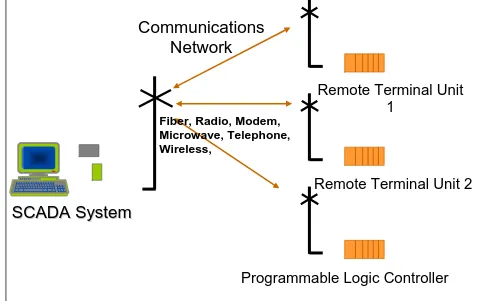
2.5 Interfacing RTU and SCADA
The way the SCADA system network (topology) is set up can vary with each system but there must be uninterrupted, bidirectional communication
properly. This can be accomplished in various ways, i.e. private wire lines, buried cable, telephone, telemetry hardware like wireless radios and modems, microwave dishes, satellites, or other atmospheric means, and many times, systems employ more than one means of communicating to the remote site. This may include dial-up or dedicated voice grade telephone lines, DSL (Digital Subscriber Line), Integrated Service Digital Network (ISDN), cable, fiber optics, WiFi, or other broadband services. [8]
Figure 2.2: Interfaced system between RTU and SCADA 2.6RTU Programming Software
This project required Isagraf 3.4 as the main software to program the RTU hardware. Isagraf supports the following 6 traditional control programming languages such as structured text, FBD editor, Quick LD editor, SFC editor, ST editor, IL editor, and Flow chart editor.
2.6.1 ISaGRAF Workbench
The ISaGRAF workbench, which is a Windows 95, 98, NT or Windows 2000 PC compatible, runs the ISaGRAF workbench software. The ISaGRAF workbench software includes:
Graphical Editors for programming: • Quick Ladder Diagram
• Function Block Diagram • Sequential Function Chart • Flow Chart
Text Editors for programming: • Instruction List
• Structured Text
Powerful tools for: • Application download
• On-line debugger and controller • Simulation
• Cross referencing
2.6.2Quick LD Editor
between high level graphic capabilities and easy to use keyboard driven programming.
2.6.2.1 Using the Quick LD editor
The LD language enables graphic representation of boolean expressions. Boolean AND , OR, NOT operators are explicitly represented by the diagram topology. Boolean input variables are attached to graphic contacts. Boolean output variable sare attached to graphic coils. The ISaGRAF Quick LD editor provides easy LD diagram entering using either keyboard or mouse. Elements are automatically linked and arranged on rungs by the Quick LD editor. No connection is drawn manually by the user. The Quick LD editor also arranges rungs in the diagram so that the space filled by the diagram is always optimized. [9]
2.6.2.2 Basics of the LD language
An LD program is expressed as a list of rungs where contacts and coils are arranged. Below are the basic components of an LD diagram:
Rung head (left power rail)
Each rung begins with a left power rail, which represents the initial "TRUE" state. ISaGRAF Quick LD editor automatically creates the left power rail when the first contact of the rung is placed by the user. Each rung may have a logical name, which can be used as a label for jump instructions. [9]
Contacts
A contact modifies the boolean data flow, according to the state of a boolean variable. The name of the variable is displayed upon the contact symbol. The following types of contacts are supported by ISaGRAF Quick LD editor: [9]