UNIVERSITI TEKNIKAL MALAYSIA MELAKA (UTeM)
Force / Torque Sensing Applied to Industrial
Robotic Deburring
Thesis submitted in accordance with the partial requirements of the Universiti Teknikal Malaysia Melaka for the Bachelor of Manufacturing Engineering
(Robotic and Automation)
By
Latifah Sulong
UTeM Library (Pind.1/2005)
SULIT
TERHAD
TIDAK TERHAD
(Mengandungi maklumat yang berdarjah keselamatan atau kepentingan Malaysia yang termaktub di dalam AKTA RAHSIA RASMI 1972)
(Mengandungi maklumat TERHAD yang telah ditentukan oleh organisasi/badan di mana penyelidikan dijalankan)
(TANDATANGAN PENULIS)
JUDUL: FORCE / TORQUE SENSING APPLIED TO INDUSTRIAL ROBOTIC DEBURRING
SESI PENGAJIAN: 2/2006-2007
Saya _____________________________________________________________________
mengaku membenarkan tesis (PSM/Sarjana/Doktor Falsafah) ini disimpan di Perpustakaan Universiti Teknikal Malaysia Melaka (UTeM) dengan syarat-syarat kegunaan seperti berikut:
1. Tesis adalah hak milik Universiti Teknikal Malaysia Melaka.
2. Perpustakaan Universiti Teknikal Malaysia Melaka dibenarkan membuat salinan untuk tujuan pengajian sahaja.
3. Perpustakaan dibenarkan membuat salinan tesis ini sebagai bahan pertukaran antara institusi pengajian tinggi.
4. **Sila tandakan (√)
LATIFAH BINTI SULONG
APPROVAL
This thesis submitted to the senate of UTeM and has been accepted as fulfillment of the requirement for the Bachelor of Manufacturing Engineering (Robotic and
Automation). The members of the supervisory committee are as follows:
……….
(Mr. Khairol Anuar bin Rakiman) Main supervisor
DECLARATION
I hereby, declare this thesis entitled “Force/ Torque Sensing Applied to Industrial
Robotic Deburring” is the result of my own research except as cited in the references.
Signature : ………
Author’s Name : ………
ABSTRACT
ABSTRAK
DEDICATION
For my parents, Sulong bin Mohammad and Halimah@Semek binti Ismail, for my
ACKNOWLEDGEMENTS
TABLE OF CONTENTS
2.2 Force / Torque Sensor Definition………...6
2.3 Previous Achievement………7
2.4 Theory of burrs formation………....14
2.5 Deburring Process………...21
2.6 Deburring Problem………...28
4.0 EXPERIMENTAL SETUP
4.1 Introduction………..32
4.2 Force/ Torque Sensor Description………...33
4.2.1 Mechanical Description of the force torque sensor………...35
4.3 Deburring tool………..36
A Aristo 6xt Specification 1 B Aristo 6xt Specification 2 C Gamma Specification
D Gamma Mechanical Properties
LIST OF FIGURES
2.1 Force/ torque sensor set up……….7
2.2 N-Joint Manipulator Mounted on a Force/Torque………...8
2.3 A PUMA 550 Manipulator Mounted on a Six-Axis Force/Torque Sensor……….9
2.4 Intelligent Robot Control Task in Defined Contact with a Moving Stiff Object Exemplified By Screw Manipulation………...10
2.5 Schematic of Force Control System………...11
2.6 Schematic of Deburring Experiment on A Superalloy Material…………...13
2.7 A schematic of robot performing a deburring operation………...15
2.8 Configuration of Automated Deburring Operation………..16
2.9 Automatic Deburring Process by robot………17
2.10 Two-link robot with semicircle constraint………...17
2.11 Schematic of a deburring task ……….18
2.12 A 2 DOF Direct-Drive Robot Equipped with Laser Displacement Sensor...19
2.13 Grasp Stability and Friction against Torque………20
2.14 The Force Profile Commanded To the Robots and the Measured Force……….21
2.15 Burr formation mechanism for orthogonal and oblique cutting………...22
2.16 Schematic description of a deburring cell with a real time acoustic feedback control………...23
2.17 Complete Framework for Robotic Deburring, Based On Three Integrated Modules………...24
2.18 Comparison between the Simulated Model………...…..25
2.19 Burr formation mechanism for orthogonal and oblique cutting………..26
2.20 CAD Directed Robotic Deburring………...26
2.21a Experiment set up for Force/ Torque sensor Deburring Process………..27
3.1 Flow Chart for Methodology………30
3.2 Flow Chart for optional Methodology………..31
4.1 Deburring Process Testing Rate………...32
4.2 Force /Torque Sensor and Grinder Attachment (planning Set up)………...33
4.3a Gamma ATI Force and Torque Sensor...34
4.3b Top view of the force and Torque Sensor………34
4.3c Bottom view of the force and Torque Sensor………..34
4.4 Force and Torque Vectors Sensed In Six Degrees of Freedom………...35
4.5 Electronic Hardware Outline……….….36
4.6 Deburring Tool Set………..36
4.6a Die Grinder Tool (mounted Point)………...37
4.6b Stright Die Grinder………...37
46c Die grinder with mounted point………...38
4.7 MTAB Aristo Arm Robot………...38
4.8 Axis Structure of Aristo Arm Robot (6 DOF)………...39
4.9 Path Planning………...40
5.1 Graph Simulated During Force………...43
5.2 Graph for Measured During Force………..44
5.3 Graph for Tensile Strength vs. Selected Material………...45
5.4 Graph for Modulus of Elasticity vs. Selected Material………...46
CHAPTER 1
INTRODUCTION
1.1 Background
In industrial tasks that require mechanical interaction with the environment, such as assembly, grinding, or milling. It is necessary to control the interaction forces if the task is to be performed successfully.
The forces and torques encountered by a robot arm can be measured by joint force sensing, wrist force sensing, and finger force sensing. The advantage of measuring arm joint forces indirectly is that a separate system of force sensors is not required. The joint forces are simply determined by measuring load variables that already exist in the system.
1.2 Problem Statements
The majority of the robots tasks require contact with the surrounding environment. That interaction generates contact forces that should be controlled in a way to finish the task correctly. Those contact forces depend on the stiffness of the tool and working objects and should be properly controlled.
The difference of the mechanical properties effected the measurement of the force and torque sensor. It is cause of the strength of the material. The force torque is attached at the end of the six degree of freedom (6DOF) of the robot arm. The 6DOF is the best application because of the maximum of the angle movement. The main components for the robotic deburring processes are robot, force torque sensor, and the grinder.
Deburring process is the removal of rough or thin. The operation is supported by the force-torque sensors, which are integrated into the end effectors. These sensors allow the measurement of the force between the workpiece and the environment. In most cases, these burrs must be removed for improved product/system performance, safety, cost, ease of assembly, elimination of stress risers, proper tolerance, appearance, etc.
1.3Objectives
The main objectives of this project are:
i. To integrate particular application into force/ torque control using robots. ii. To understand the force and torque sensor use in deburring process
1.4Scope of the Project
The scopes of the project are:
i. Planning the experiment set up for robotic deburring base on the force/ torque sensor by using several difference material selections.
ii. Investigate the problem occur in experimental set up planning.
iii. Do analysis on the force and torque reading especially for different materials.
1.5Project Outline
This report of the Project is organized into six chapters. The chapter is described as follows:
Chapter I discusses the objective, scope and importance of the study.
Chapter II relates the literature review related to the various uses and application
force/ torque sensor in deburring process.
Chapter III described the proposed methodology which is the experimental
Chapter IV planning the experimental set up.
Chapter V shows the expected result that can get from the related experiment from past researcher. Analysis and discuss the expected data. A comparison was made to find the theoretical relationship.
Chapter VI summarizes the overall analysis of the study and also suggests works
CHAPTER 2
LITERATURES REVIEW
2.1 Introduction
Sensor is used as peripheral devices in robotics. Sensor also used as integral components
of the robot’s position feedback control system. The sensors used in robotics include a
wide range of devices. The major use of sensors in industrial robotics and other automated manufacturing systems can be divided into three basic categories. The categories are safety monitoring, interlocks in work cell control and part inspection for quality control.
The safety monitoring is Concern the protection of human workers who work in the vicinity of the robot or other equipment. Interlocks in work cell control are used to coordinate the sequences of activities of the different pieces of equipment in the work cell. In the execution of the robot program, there are certain elements of the work cycle whose completion must be verified before proceeding with the next element in the cycle. Part inspection for quality control used to determine variety of part quality characteristics. It also determines position and related information about objects in the robot cell.
reasonable small, built in several sizes to adapt the different robot bolt patterns and load capacities, and mechanically resistant (Pires et al, 1999).
2.2 Force / Torque Sensor Definition
The interaction forces and torques which appear, during mechanical assembly operations, at the robot hand level can be measured by sensors mounted on the joints or on the manipulator wrist. The first solution is not too attractive since it needs a conversion of the measured joint torques to equivalent forces and torques at the hand level. The forces and torque measured by a wrist sensor can be converted quite directly at the hand level.
Wrist sensors are sensitive, small, compact and not too heavy, which recommends them for force controlled robotic applications. A wrist force/torque has a radial three or four beam mechanical structure. Two strain gages are mounted on each deflection beam. Using a differential wiring of the strain gages, the four -beam sensor produces eight signals proportional with the force components normal to the gage planes. Using a
6-by-8 “resolved force matrix”, the eight measured signals are converted to a 6-axis
2.3 Previous Achievement
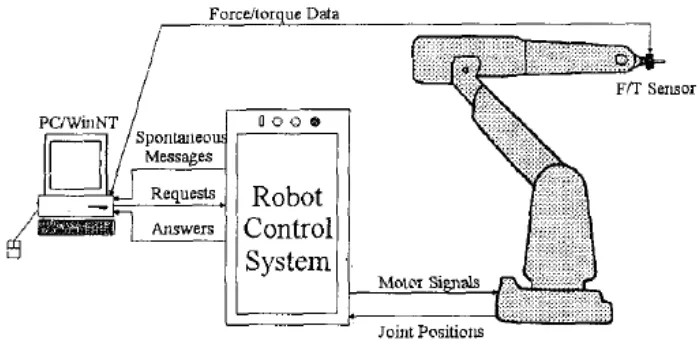
Figure 2.1: Force/ torque sensor set up (Pires J.N et al,1998)
In this section a set of software tools designed to program, control and monitor the industrial robot (ABB IRl31400 equipped with the new control system). The main objective is to design tools to add force control capabilities to the original setup (robot and controller). A PC based wrist mounted force/torque sensor (from JR3 Inc.) was installed on the robot. The basic setup is presented on figure 2.1. The software developed is divided into four main parts are robot communication software, force/torque sensor access and configuration software, connectivity to windows applications software and force control application software.
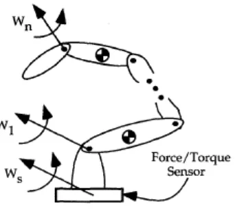
Figure 2.2: N-Joint Manipulator Mounted on a Force/Torque Sensor (Liu.G. et all, 1998)
An n-joint manipulator mounted on a six-axis base force/torque sensor, such as shown in Figure 2.2. The manipulator is mounted on a base force/torque sensor. Sensor measurements and joint velocities recorded during manipulator motion are used to identify the inertial parameters.
The sensor measurements are used to identify the inertial parameters. The manipulator has n+l links, where link 0 and link n is the base and the terminal link, respectively. The wrench measured by the base force sensor is denoted as Ws. (Liu.G. et all, 1998).
These parameters can be estimated using the manipulator's joint torques and forces along with the joint positions and velocities. Most robot manipulators are not equipped with joint force/torque sensors. A typical estimate is from the motor current. A major difficulty with this method is that the joint torque/force estimation accuracy is limited by unmodeled joint friction and actuator dynamics. A base-mounted force/torque sensor has been used to estimate mass properties of a manipulator statically.
manipulator's joint torques and forces along with the joint positions and velocities. A major difficulty with this method is that the joint force/torque estimation accuracy is limited by unmodeled joint friction and actuator dynamics.
A base-mounted force torque sensor has been used to estimate mass properties of a manipulator statically. The manipulator is mounted on a six-degree-of-freedom force sensor and the reaction forces and moments at its base are measured for different manipulator positions and base orientations. A base-mounted force torque sensor was used to estimate inertial properties of a manipulator, without requiring base reorientation.
The robot manipulator is mounted on an external base force/torque sensor. The force torque sensor measures a wrench that corresponds only to the forces and torques effectively applied to the manipulator's links. (Liu.G. et al, 1998).
Figure 2.3: A PUMA 550 Manipulator Mounted on a Six-Axis Force/Torque Sensor (Liu.G. et al, 1998)
AMTI six-axis force/torque sensor as shown in Figure 2.3. Only the first two joints of the PUMA were actuated, in order to reduce model complexity. Joints three, four, and five were immobilized.
The base force/torque sensor is external to the manipulator. The same sensor can be used for parameter estimation for different robot manipulators. The accuracy depends on the measurement accuracy of the force/moment sensor.
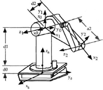
Figure 2.4: Intelligent Robot Control Task in Defined Contact with a Moving Stiff Object Exemplified By Screw Manipulation ( Maab. R. et al, 1994)
The 6 DOF robot is equipped with position sensors and 6 DOF force/torque sensor, which are integrated in two separate feedback paths.
The proposed control concept was developed to implement the following features to force/position control of robot manipulators. The control concepts are cartesian space data processing of sensor and trajectory data, singularity robust inverse kinematics, adjustment of desired trajectories to kinematic and dynamic constraints, neural network (NN) for mapping operations and neural model based dynamic controller.
The simulation results demonstrate the feasibility of the proposed concept. The force/sensor was simulated using a model with static and kinematics equations. The robot finds the correct orientation of the screw by reducing all forces and torques.
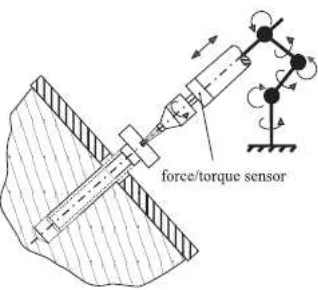
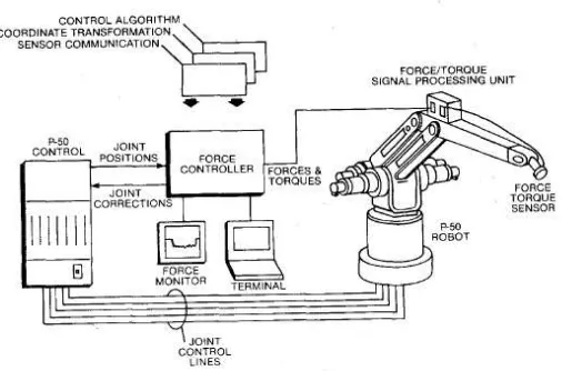
Figure 2.5: Schematic of Force Control System ( Stephien et al, 1987)
The force control system presented has applications in a wide range of manufacturing
problems because of the system’s ability to regulate contact force in an arbitrary