Customized Fault Management System for Low Voltage (LV) Distribution
Automation System
M.M Ahmed, W.L Soo, M. A. M. Hanaiah and M. R. A. Ghani
x
Customized Fault Management
System for Low Voltage (LV)
Distribution Automation System
M.M Ahmed, W.L Soo, M. A. M. Hanafiah and M. R. A. Ghani
University Technical Malaysia Melaka (UTeM)
Malaysia
1. Introduction
Supply disruption such as overloading will cause interruptions of electricity supply to customers. The technicians have to manually locate the fault point and this tedious work may last for extended periods of time. The other reasons are the lack of use of efficient tools for operational planning and advanced methodology for quick detection of fault, isolation of the faulty section and service restoration. Currently, fault detection, isolation and service restoration takes a long time causing the interruption of supply for a longer duration.
An active development phase of information technology has given significant impact to the distribution network fault management. There is a tendency towards fully automated switching systems with the introduction of Supervisory Control and Data Acquisition (SCADA) systems. The decision making feature of the fault management system is depend on SCADA system. SCADA can be used to handle the tasks which are currently handled by the people and can reduce frequency of periodic visit of technical personal substantially. SCADA is a process control system that enables a site operator to monitor and control processes that are distributed among various remote sites. The control functions are related to switching operations, such as switching a capacitor, or reconfiguring feeders. Once the fault location has been analyzed, the automatic function for fault isolation and supply restoration is executed. When the faulty line section is encountered, it is isolated, and the remaining sections are energized. This function directly impacts the customers as well as the system reliability.
This chapter presents the development of a fault management system for distribution automation system (DAS) for operating and controlling low voltage (LV) downstream system such as 415 V for three phase system and 240 V for single phase system. The fault management system is referred as the fault detection, fault location, fault isolation, electricity restoration and automatic operation and control. This done because system is equipped with automated equipment to detect earth fault and over-current faults and identify them accordingly. An embedded controller with Ethernet access is used as remote terminal unit (RTU) to act as converter for human machine interface (HMI) and to interact with the digital input and output modules. Supervisory Control and Data Acquisition (SCADA) is integrated with the RTU for automatic operating and controlling the distribution system. The laboratory results are compared with the simulation results to verify the results and make the achieved results credible.
2. Substation Model
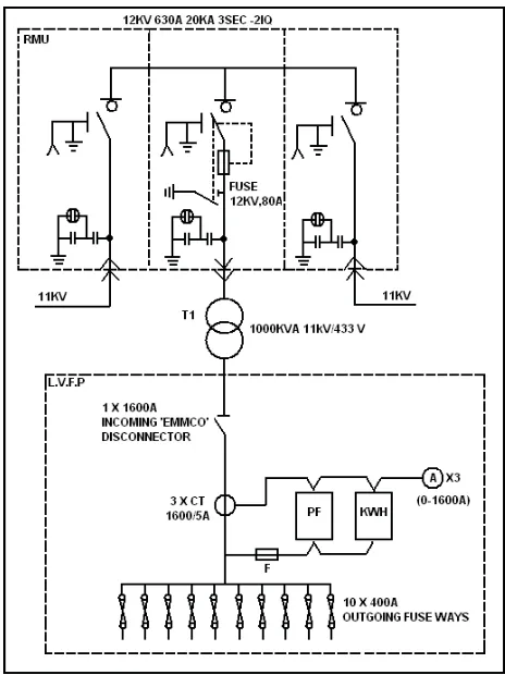
Fig. 1 shows a typical compact substation which is also referred as Ring Main Unit (RMU).
RMU can be obtained by arranging a primary loop, which provides power from two feeders. Any section of the feeder can be isolated without interruption, and primary faults are reduced in duration to the time required to locate a fault and do the necessary switching to restore service. A 12KV, 630A, 20KVA RMU is supplying power supply to Low Voltage Feeder Panel. A three-phase, 1000KVA, 11/0.433 kV transformer is used to step down 11kV to 433V before supplying to Low Voltage Feeder Panel (LVFP).
Fig. 1. Typical Substation
The outgoing loads are protected by fuses which have to be replaced if fault occurs. In this research project, fuses have been replaced by circuit breaker which can be manually or automatically controlled for switching operation and are not frequently replaced as shown in Fig. 1. The typical panel shown in Fig. 1 is using power factor meter, kilowatt hour meter and three ammeters to provide reading of power factor, kilowatt hour and three phase current values. Instead of using different types of meters to provide the reading, a single power analyzer is used in this research to provide the same reading and is able to send the data to the controller using modbus protocol. In this research, the service substation panel consists of four feeder points and each feeder is connected to customer service substation panel as shown in Fig.2.
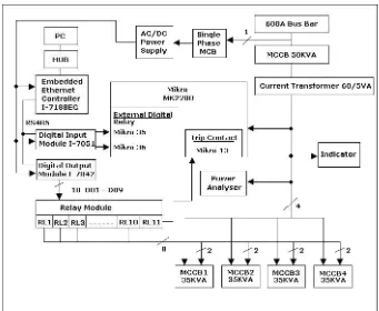
In Fig. 2, the service substation block diagram consists of power line and control line. The power line shows the electricity power supply supplied to all the components in service substation panel. The controller and I/ O modules are supplied with dc power supply. Relay module received power supply from the digital output module. The control line shows the communication line between the controller and I/O modules.
Electromechanical relays are interfaces that control one electrical circuit by opening and closing its contacts in another circuit. An electromechanical relay is a relay with sets of contacts which are closed by magnetic force that includes magnetic coil and contacts. Electromechanical relays are limited to switching about 15A but are capable of switching several different circuits simultaneously.
Current transformers (CTs) are used in power installations for supplying the current to circuits of indicating instruments such as ammeter and wattmeter and protective relays. CTs are used so that ammeters and the current coils of other instruments and relays need not be connected directly to high-current lines. These instruments and relays are insulated from high currents. CTs also step down the current to a known ratio. The secondary winding is rated at 5A regardless of the current rating of the primary winding.
MK2200 which is the combination of overcurrent and earth leakage relay is used. The 630A, 50kVA, 415V MCCB is used as the main MCCB. The MCCBs are switched on or off by using customized solenoids.
RMU can be obtained by arranging a primary loop, which provides power from two feeders. Any section of the feeder can be isolated without interruption, and primary faults are reduced in duration to the time required to locate a fault and do the necessary switching to restore service. A 12KV, 630A, 20KVA RMU is supplying power supply to Low Voltage Feeder Panel. A three-phase, 1000KVA, 11/0.433 kV transformer is used to step down 11kV to 433V before supplying to Low Voltage Feeder Panel (LVFP).
Fig. 1. Typical Substation
The outgoing loads are protected by fuses which have to be replaced if fault occurs. In this research project, fuses have been replaced by circuit breaker which can be manually or automatically controlled for switching operation and are not frequently replaced as shown in Fig. 1. The typical panel shown in Fig. 1 is using power factor meter, kilowatt hour meter and three ammeters to provide reading of power factor, kilowatt hour and three phase current values. Instead of using different types of meters to provide the reading, a single power analyzer is used in this research to provide the same reading and is able to send the data to the controller using modbus protocol. In this research, the service substation panel consists of four feeder points and each feeder is connected to customer service substation panel as shown in Fig.2.
In Fig. 2, the service substation block diagram consists of power line and control line. The power line shows the electricity power supply supplied to all the components in service substation panel. The controller and I/ O modules are supplied with dc power supply. Relay module received power supply from the digital output module. The control line shows the communication line between the controller and I/O modules.
Electromechanical relays are interfaces that control one electrical circuit by opening and closing its contacts in another circuit. An electromechanical relay is a relay with sets of contacts which are closed by magnetic force that includes magnetic coil and contacts. Electromechanical relays are limited to switching about 15A but are capable of switching several different circuits simultaneously.
Current transformers (CTs) are used in power installations for supplying the current to circuits of indicating instruments such as ammeter and wattmeter and protective relays. CTs are used so that ammeters and the current coils of other instruments and relays need not be connected directly to high-current lines. These instruments and relays are insulated from high currents. CTs also step down the current to a known ratio. The secondary winding is rated at 5A regardless of the current rating of the primary winding.
MK2200 which is the combination of overcurrent and earth leakage relay is used. The 630A, 50kVA, 415V MCCB is used as the main MCCB. The MCCBs are switched on or off by using customized solenoids.
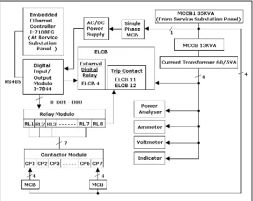
In Fig. 3, the customer service substation block diagram also consists of power line and control line. The power line starts from MCCB1 from the service substation panel. Digital input/output module is supplied with direct current power supply. The contactor module is connected to the ac power supply. Relay module received power supply from the digital input/output module. The control line shows that the digital input/output module is connected with the controller in the service substation panel.
Relays are connected to contactors to energize or de-energize loads. Contactors typically have multiple contacts, and those contacts are usually normally-open, so that power to the load is shut off when the coil is de-energized. The top three contacts switch the respective phases of the incoming three-phase AC power. The lowest contact is "auxiliary" contact. A normally-closed relays are connected to this auxiliary contact in series so that when the relays are opened, contactor coils will automatically de-energize, thereby shutting off power to the load.
Fig. 3. Customer Service Substation System Block Diagram
3. Relays
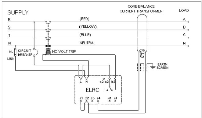
In this research work, zero-phase sequence current transformer is connected to the earth leakage relay as show in Fig. 4. Earth Leakage Circuit Breaker (ELCB) works in the same
way as the Residual Current Circuit Breaker (RCCB) and as such, must be accompanied by a circuit breaker (CB) or a fuse. Phase and neutral conductors are passed through a toroidal transformer, creating a magnetic field proportional to its current. In normal situations, the vector sum of the currents is zero even with unbalanced three-phase loads. The magnitude of the zero sequence current increases beyond its normal value when a ground fault is experienced. If the magnitude of the estimated zero sequence current is more than a threshold value in earth leakage relay, it is assumed that one or two phases are short circuited to ground. The short circuit between one phase and earth is probably the most common type of fault on low voltage electrical installations. This research project is focusing on earth fault.
Fig. 4. Typical Circuit of ELCB with Current Transformer
A leakage current towards earth on one or more conductors at the downstream of the toroid causes an imbalance which is detected in the measurement winding and sent to an amplifier relay. The amplifier relay receives the signal from the ring current transformer and compares it with the preset threshold value. The relay output is turned on in the case where the detected value is higher than the preset threshold and lasts for a longer time than the preset tripping time value. The output remains in the on state until the relay is reset either manually or electrically. Generally, the relay output is fed to the shunt trip of a protective device such as CB which isolates the faulted circuit.
In Fig. 3, the customer service substation block diagram also consists of power line and control line. The power line starts from MCCB1 from the service substation panel. Digital input/output module is supplied with direct current power supply. The contactor module is connected to the ac power supply. Relay module received power supply from the digital input/output module. The control line shows that the digital input/output module is connected with the controller in the service substation panel.
Relays are connected to contactors to energize or de-energize loads. Contactors typically have multiple contacts, and those contacts are usually normally-open, so that power to the load is shut off when the coil is de-energized. The top three contacts switch the respective phases of the incoming three-phase AC power. The lowest contact is "auxiliary" contact. A normally-closed relays are connected to this auxiliary contact in series so that when the relays are opened, contactor coils will automatically de-energize, thereby shutting off power to the load.
Fig. 3. Customer Service Substation System Block Diagram
3. Relays
In this research work, zero-phase sequence current transformer is connected to the earth leakage relay as show in Fig. 4. Earth Leakage Circuit Breaker (ELCB) works in the same
way as the Residual Current Circuit Breaker (RCCB) and as such, must be accompanied by a circuit breaker (CB) or a fuse. Phase and neutral conductors are passed through a toroidal transformer, creating a magnetic field proportional to its current. In normal situations, the vector sum of the currents is zero even with unbalanced three-phase loads. The magnitude of the zero sequence current increases beyond its normal value when a ground fault is experienced. If the magnitude of the estimated zero sequence current is more than a threshold value in earth leakage relay, it is assumed that one or two phases are short circuited to ground. The short circuit between one phase and earth is probably the most common type of fault on low voltage electrical installations. This research project is focusing on earth fault.
Fig. 4. Typical Circuit of ELCB with Current Transformer
A leakage current towards earth on one or more conductors at the downstream of the toroid causes an imbalance which is detected in the measurement winding and sent to an amplifier relay. The amplifier relay receives the signal from the ring current transformer and compares it with the preset threshold value. The relay output is turned on in the case where the detected value is higher than the preset threshold and lasts for a longer time than the preset tripping time value. The output remains in the on state until the relay is reset either manually or electrically. Generally, the relay output is fed to the shunt trip of a protective device such as CB which isolates the faulted circuit.
MK2200 has six relay outputs of which 4 are user configurables. R1 contact is the dedicated trip contact and cannot be programmed. Either EF or overcurrent will activate this contact. The relay output remains in the on state until the relay is reset either manually or electrically. Generally, the relay output is fed to the shunt trip of a protective device such as CB which isolates the faulted circuit. Contact R2, R3, R4 and R5 are user configurable outputs. The sixth output contact internal relay failure (IRF) is also not user programmable. It is used to signal an internal failure of MK2200.
When the auxiliary power of MK2200 is switched on, the relay starts its operation. If the MK2200 is functioning normally, the IRF output is energized hence the normally close (NC) contact of the output will open and the normally open (NO) contact will close.
Fig. 6 shows the typical connection diagram of MK2200 with Current Transformer (CT). MK2200 works in the same way as the Residual Current Circuit Breaker (RCCB) and as such, must be accompanied by a Circuit Breaker (CB) or a fuse. Phase and neutral conductors are passed through a toroidal transformer, creating a magnetic field proportional to its current. In normal situations, the vector sum of the currents is zero even with unbalanced three-phase loads.
Fig. 5. Pin Assignment of MK2200
Fig. 6. MK2200 Typical Connection Diagrams
4. Fault Isolation Methods
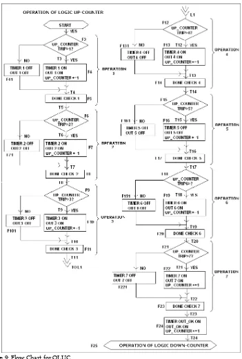
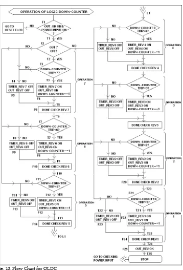
Fig. 7. General Flow Chart
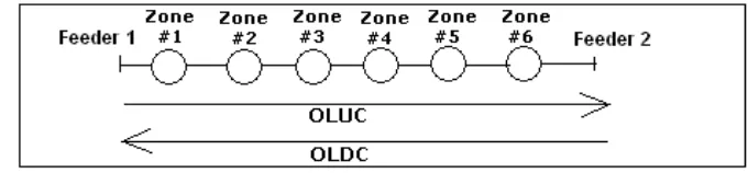
First step is to check the power input whether it is turned on or turned off. If no faulty condition detected by ELCB, power input is turned on. When ELCB detects the fault condition, power input is turned off. In this case, the ELCB is resetted by using a delay timer and power input is turned on. There are two modes of operations. If automatic mode is selected, when fault occurs, the fault point is isolated automatically by activating the OLUC and OLDC. OLUC and OLDC are executed and only the fault point is isolated and the unaffected points are operated as normal condition. Once the fault point is operated as normal, the 'reset programme' button is pressed. This button resets back the counter to initial value and executes the OLUC and OLDC again.
Fig. 8. OLUC and OLDC Descriptions
IF mode_auto & OLUC_done & LastFeederOn & trip_counter_oldc < u
{
Fig. 7. General Flow Chart
First step is to check the power input whether it is turned on or turned off. If no faulty condition detected by ELCB, power input is turned on. When ELCB detects the fault condition, power input is turned off. In this case, the ELCB is resetted by using a delay timer and power input is turned on. There are two modes of operations. If automatic mode is selected, when fault occurs, the fault point is isolated automatically by activating the OLUC and OLDC. OLUC and OLDC are executed and only the fault point is isolated and the unaffected points are operated as normal condition. Once the fault point is operated as normal, the 'reset programme' button is pressed. This button resets back the counter to initial value and executes the OLUC and OLDC again.
Fig. 8. OLUC and OLDC Descriptions
IF mode_auto & OLUC_done & LastFeederOn & trip_counter_oldc < u
{
5. Results and discussions
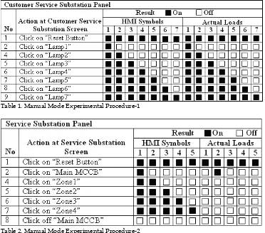
Both ELCB and MK2200 are fitted with test and reset buttons in order to conduct testing and commissioning of the relays. 32 bit microprocessor-based power quality analyzer is used to measure phase voltage and phase current of the incoming power supply to both panels. The power analyzer is connected using three phase, four-wire input connections for unbalanced loads. The setup procedures are done by using the keypad. It sends data to the controller using RS485 network. Table 1, Table 2, Table 3 and Table 4 are the results obtained by the following procedures described in the tables.
Table 1. Manual Mode Experimental Procedure-1
Table 2. Manual Mode Experimental Procedure-2
By conducting the actual experiments, the appropriate delay timer for controlling the solenoid operation in service substation and also loads in customer panel are obtained. Fig. 11, Fig. 12, Fig. 13, Fig. 14 and Fig. 15 show graphs build using Excel to show the change of phase current for customer service substation panel and service substation panel during fault isolation operation done by the system. The duration time 1 is the time period that needed by the system to identify which load is the fault load. In this experiment, the Zone 4
and Zone 5 were chose to be the fault zones. Duration time 2 is the time period that is needed by the system to isolate the faulted load and restore electricity power supply to the rest of the healthy loads. Outage time is the duration of time that the customer experienced electricity power supply disruption. Reset time is the total time needed to restore electricity power supply to all the loads including the faulted load that already been repaired.
Table 3. Automatic Mode Experimental Procedure-1
5. Results and discussions
Both ELCB and MK2200 are fitted with test and reset buttons in order to conduct testing and commissioning of the relays. 32 bit microprocessor-based power quality analyzer is used to measure phase voltage and phase current of the incoming power supply to both panels. The power analyzer is connected using three phase, four-wire input connections for unbalanced loads. The setup procedures are done by using the keypad. It sends data to the controller using RS485 network. Table 1, Table 2, Table 3 and Table 4 are the results obtained by the following procedures described in the tables.
Table 1. Manual Mode Experimental Procedure-1
Table 2. Manual Mode Experimental Procedure-2
By conducting the actual experiments, the appropriate delay timer for controlling the solenoid operation in service substation and also loads in customer panel are obtained. Fig. 11, Fig. 12, Fig. 13, Fig. 14 and Fig. 15 show graphs build using Excel to show the change of phase current for customer service substation panel and service substation panel during fault isolation operation done by the system. The duration time 1 is the time period that needed by the system to identify which load is the fault load. In this experiment, the Zone 4
and Zone 5 were chose to be the fault zones. Duration time 2 is the time period that is needed by the system to isolate the faulted load and restore electricity power supply to the rest of the healthy loads. Outage time is the duration of time that the customer experienced electricity power supply disruption. Reset time is the total time needed to restore electricity power supply to all the loads including the faulted load that already been repaired.
Table 3. Automatic Mode Experimental Procedure-1
Table 5. Automatic Mode Experimental Procedure-2 Continue
Fig. 11. Phase Current Graph for Delay Timer Six Seconds
Table 5 shows the total of restoration time for service substation panel. In the service substation panel, if the delay timer is set to fast, the solenoid will not be able to switch on or off the MCCB. The minimum delay timer needs to be set to five seconds for proper switching operation of the MCCBs by the solenoids. The results in Table 5 can only be applied using LKE LKS-600S MCCB and LKE LKS-100N MCCB with shunt trip operating time of five to fifteen minutes.
Fig. 12 Phase Current Graph for Delay Timer Three Seconds
Panel Duration Time 1 Duration Time 2 Total of time
Service Substation 25 seconds 25 seconds 50 seconds Table 6. Total Minimum Restoration Time for Service Substation Panel
Fig. 13. Phase Current Graph for Delay Timer One Second
substation is set to six seconds, three seconds, one seconds, five hundred milliseconds and one hundred milliseconds.
Fig. 14. Phase Current Graph for Delay Timer Five Hundred Milliseconds
Fig. 15. Phase Current Graph for Delay Timer One Hundred Milliseconds
Table 7 shows the minimum total of restoration time for customer service substation panel and service substation panel. The ELCB minimum operation time is fifty milliseconds. In this case, the delay timer has to be set higher than fifty milliseconds. The minimum delay timer for customer service substation panel is one hundred milliseconds.
Delay Timer
(Second) Duration Time 1 (Second) Duration Time 2 (Second) Outage Time (Second) Reset Time (Second)
6 24 30 54 42
3 12 15 33 21
1 4 5 15 7
0.5 2 2.5 10.5 3.5
0.1 - - - 0.7
Table 6. Restoration Time for Customer Service Substation Based on Delay Timer
Panel Minimum Restoration Time (Second)
Customer Service Substation 0.7
Service Substation 50
Table 7. Minimum Total of Restoration Time
Experiment Total of
Experiment Steps Total of Correct Operation Total of Failure Operation Percentage of Failure Operation (%)
6. Conclusion
In this research, a Customized SCADA is built to provide automatic fault isolation for low distribution system. The contribution of this research includes developing a complete fault isolation algorithm based on an open loop distribution system. Service Substation Panel, Customer Service Substation Panel and Customer Panel have been built to validate the beginning, this algorithm needs to clarify with which point is the fault point by supplying the power supply to each load after the fault is detected by the ELCB. When the fault point is being activated, the ELCB detects the fault and trip mechanism is operated. The algorithm will find the false point and reset the ELCB to restore the power supply to the loads. This time, only the un-faulted point will be restored. In Customer Service Substation panel, two contactors are used to activate one load. Although in Service Substation panel only uses one feeder, the same algorithms (OLUC and OLDC) are applied to control the switching operation of MCCBs by using customized solenoid. MCCBs have trip mechanism that is able to detect faults. MCCBs are different from the loads used in Customer Service Substation because they don't need to be accompanied by two switching devices to control their operations.
The HMI is capable to communicate with the I/O devices. An HMI for SCADA is developed in this research by using an embedded Ethernet controller as the converter to communicate with the I/ O devices. By integrating the ELCB and MK2200 into the SCADA system, the SCADA system is capable to respond to the faults by resetting both devices in order for the algorithm to check the fault point.
Based on the experimental results, the system correctly locates the fault point, isolates the fault point and reenergizes the un-faulted loads. However, during the fault isolation operation, the system has to detect the fault point by simply switching on the fault load. After the system acknowledges the fault point, the appropriate switching functions are executed. The developed system has a potential in reducing the outage time while comparing to the manual operation by the technicians and engineers.
From the analysis done, the outage times for both panels to locate fault and restore electricity power supply to healthy loads are 50.7 seconds. By assuming that it takes 1 hour for the technician to restore the electricity power supply, thus there is a 98.59% improvement in the outage time operation. This system will help the utility company to save money if the outage times are reduced. As described in Table 8, the failure percentage for the system in detecting the fault and isolating the fault point is none. This means that the system is reliable.
7. Future Research
The future research work should be aimed at developing of full scale Distribution Automation system, which can cover from primary substations to consumer level intelligent automation. Here are few recommendations which will lead new research projects in the future:
a) Automated solutions to the distribution system comprising automation-ready made building blocks such as a synthesis of state-of-the-art individual components (distribution switchgear, fault passage indication, RTU, local power supplies, and communications interfaces), integrated to form complete functional devices. These devices are assembled into a system to solve the complete control or automation needs of each distribution network.
b) Data collection of not only the status of CBs and relays but also status of each component in the panels. This will help to reduce black-out due to equipment malfunctions.
c) Develop a standard Distribution Automation software such as master distribution automation software, customer information system (CIS), trouble call management software (TCMS) and web based monitoring of distribution system.
8. References
Austerlitz, H. (2003). Data Acquisition Technique Using PCs. 2nd ed. California: Academic
Press, 416p. ISBN: 0-12-068377-6
Clarke, G. (2004). Practical Modern SCADA Protocols: DNP3, 60870.5 and Related Systems, Massachusetts Newness, 1st ed., 743p. ISBN 07506 7995
Glover, J.D. & Sarma M.S. (2002). Power System Analysis and Design., California: Pacific Grove, 3rd ed., 527
p. ISBN 0-534-95367-0
Pabla, A.S. (2005). Electric Power Distribution, 2nd ed., New York: McGraw-Hill, 723 p. ISBN
0-07-144783-0
Lee, H.J. & Park, Y.M. (1996). A Restoration Aid Expert System for Distribution Substations. IEEE Transactions on Power Delivery, Vol. 11, pp.1765 -1769
Hsu, Y.Y & Huang, H.M. (1995). Distribution System Service Restoration using the Artificial Neural Network Approach and Pattern Recognition Method. IEEE Proceeding Generation Transmission
Distribution, Vol. 142, No.3, pp.251-256.
Hsiao, Y. T. & Chien, C. Y. (2000). Enhancement of Restoration Service in Distribution Systems using a Combination Fuzzy-GA Method. IEEE Transactions on Power Systems, vol. 15, no. 4, November
2000, pp. 1394-1400
Edited by Wei Zhang
ISBN 978-953-307-037-7 Hard cover, 504 pages
Publisher InTech
Published online 01, March, 2010
Published in print edition March, 2010
InTech Europe
University Campus STeP Ri Slavka Krautzeka 83/A 51000 Rijeka, Croatia Phone: +385 (51) 770 447 Fax: +385 (51) 686 166 www.intechopen.com
InTech China
Unit 405, Office Block, Hotel Equatorial Shanghai No.65, Yan An Road (West), Shanghai, 200040, China
Phone: +86-21-62489820 Fax: +86-21-62489821
In this book, a number of innovative fault diagnosis algorithms in recently years are introduced. These methods can detect failures of various types of system effectively, and with a relatively high significance.
How to reference
In order to correctly reference this scholarly work, feel free to copy and paste the following:
M.M Ahmed, W.L Soo, M. A. M. Hanafiah and M. R. A. Ghani (2010). Customized Fault Management System for Low Voltage (LV) Distribution Automation System, Fault Detection, Wei Zhang (Ed.), ISBN: 978-953-307-037-7, InTech, Available from: