Procedia Engineering 53 ( 2013 ) 645 – 649
1877-7058 © 2013 The Authors. Published by Elsevier Ltd.
Selection and peer-review under responsibility of the Research Management & Innovation Centre, Universiti Malaysia Perlis doi: 10.1016/j.proeng.2013.02.083
Malaysian Technical Universities Conference on Engineering & Technology 2012, MUCET 2012
Part 2 Mechanical And Manufacturing Engineering
Greenhouse Gas Reduction by Utilization of Cold LNG Boil-off Gas
Mohamad Shukri Zakariaª*, Kahar Osmanª, Haslina Abdullah
bªFaculty of Mechanical Engineering
This paper present the analysis of utilization the cryogenic temperature of Boil off Gas (BOG) from Liquefied Natural Gas (LNG) to flow air inside insulation space of LNG. Three Dimensional geometry of the tank are model in Computational Fluid Dynamic (CFD) ANSYS Fluent software package using steady state and K-Epsilon turbulence model. Result shows that almost 60% of BOG can be prevented from flared to the atmosphere thus will reduce Greenhouse Gas (GHG) emission and pollution.
© 2013 The Authors. Published by Elsevier Ltd.
Selection and/or peer-review under responsibility of the Research Management & Innovation Centre, Universiti Malaysia Perlis.
Keywords: LNG; emission; CFD; heat transfer, cyrogenic
1.Introduction
Current concern on the Greenhouse Gas (GHG) emission has made Natural Gas become popular choices of energy sources compared to crude oil or coal.Liquefied natural gas (LNG) is Natural Gas (NG) that has been cooled to 110K, changing it from gas to the liquid, 1/600th from its original volume. NG is a nontoxic, colorless, odorless, and noncorrosive fossil fuel. LNG is transported with vessels having cryogenic tanks without any refrigeration. Therefore, a significant fraction of the cargo LNG volume evaporates during voyage, which is usually called Boil-Off Gas (BOG).
The generated Boil off gas (BOG) from LNG tank can be manage by a few methods such as flaring, propulsion[1,2] and re-liquefaction[3-5]. Flaring happened when the quantity of BOG exceeds the actual capacity. It is for security reasons. LNG also can be treating as propulsion where the generated BOG was burned in the boiler and give power input to the ship. Re-liquefaction is one of the method to handle the BOG by changing the BOG to the LNG back by compressed the BOG in the form of gas to the LNG in the form of liquid. In this paper , new method in handling BOG has been proposed which is utilize it as an insulation to minimize the BOG formation inside cryogenic tank.
Flaring is high temperature oxidation process to burn combustible component of waste gases. Natural Gas consists of over 95% of waste gases flare [6]. Although the amount of gas flared and vented is small which is 3% of the world production of Natural Gas, the combustion from flaring process will produce emission gas such as CO2, Co and NOx and contributes to Global Greenhouse Gas emission. Furthermore, it also has the least CO2 emission per unit energy and releases 1.9 times less CO2 than coal as point out by[7].
* Corresponding author. E-mail address: [email protected], [email protected] © 2013 The Authors. Published by Elsevier Ltd.
It is also widely acknowledged that recently flaring and venting of Boil-Off Gas from LNG are greatly contributed to the Greenhouse Gas (GHG) emission, which is sure will give negative impact to the environment [6]. The World Bank also reported that the annual amount of vented or flared gas to the atmosphere are equivalent to the combination of the gas consumption of the country France and Germany, twice the gas consumption of Africa, three quarter of the Russian gas export or sufficient to supply the all country in the world with the gas for 20 days.
2.Methodology
To analyze boil-off rate (BOR) for LNG tanker during storage, simulation had been done using computational fluid dynamic software FLUENT 6.3.26 and GAMBIT 2.3.16 from ANSYS Incorporation(ANSYS).
At initial analysis, the boil-off rate for three dimensional of LNG tanker was investigated. The initial condition and boundary condition variables were determined before numerical solution analysis executed. As a result, the BOR specific case is determined.
For further analysis, the tube cooled shield has been introduced as one of the insulation for LNG tank
2.1.Geometry
In this paper, we used GTT NO96 LNG membrane type tanker for analysis purpose since its cover more than half of total LNG tanker used around the world [8].
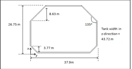
Two dimensional dimensions of the tank in this paper is refer to the work done by [9] are shown in Figure 1 with capacity of 40447 m3 corresponding to the ship size of 160000 m3. The three dimensional geometry was constructed using software GAMBIT and mesh using tetrahedral element.
Since temperature change in each cycle of the air through the spiral tube is relatively smaller than the total temperature change throughout the entire tube as reported by [10], it is possible to assume that the air flow axially along tank width in the parallel plate configuration, instead of complicated 3D spiral flow geometry of the air in the tube
The corresponding thickness of the tank insulation taken as 0.53m while the thickness of the parallel plate shield taken as 0.0254 m (1 inch). Larger thickness of the shield plat shield should be avoided in order to support the weight of the tank. There are no shield element installed on the xy-plane as can seen from Figure 2 since the temperature at that location are constant and controlled by heating coil element.
2.2.Boundary Condition
All side of the tank except the upper side taken as wall properties boundary condition with specific value for boundary condition according to the real industry practice. While the upper side of tank set with pressure outlet boundary condition to enable liquid and vapor exit or backflow depends on the corresponding pressure at the outlet. In this case, it is assume that the outlet pressure are 101.3 kPa in lieu with the real operation pressure of LNG whereas slightly higher than atmospheric pressure [7].
Temperature at the outer wall of the tank is divide into three parts. There are 318K at side wall above water level and roof, 305K at side wall below water level and bottom, and 278K at front and back side wall of tank located inside cofferdam area between the tanks onboard LNG ship,which is in line with "International Code for the Construction and Equipment of Ships
Fig. 1. Dimension of the LNG tank used in the present study
2.3.Material Properties
Two volumes are defined in the model. There is structural volume covers from outer shell to the inner shell of the tank expose to the cargo, which is represent material of main insulation, outer steel, inner steel ,area of support junction, aggregate with different size, angle iron, ballast medium and so on. Overall heat thermal transmittance represent all this material taken as 0.411 kJ/h.m2.K as reported by [7].
The other one is represents the air medium flowing through the spiral tube which was simplified as a parallel plate as indicate by [10]. Thermal conductivity of the air is taken as 0.0242 w/mK with density 1.225 kg/m3.
In order to compute the BOG amount, Latent heat vaporization and density taken as 511000 J/kg and 424 kg/m3 respectively as provided by [11]by assuming that the composition of LNG consist of 100% methane and will be used in the Equation (1).
2.4.Computing BOG
BOG is computed in terms of Boil-off Rate (BOR). BOR means how much percentage of LNG need to be boiled off in order to keep the LNG in same temperature when heat is added to the LNG fuel [8]. The heat leakage thru the tank is one of the main factors for the increasing of BOR. The energy required for the LNG vaporization process is provided by the heat transferred from cargo tank to the fluid. The heats leakage are compute for each side of the tank which is roof, side and bottom [12]
The key parameters in determining the BOG formation are density and enthalpy of the LNG. Several model and equation appearing in literature [12,13] is to estimate the density of the natural gas vapor. They used Benedict-Webb-Rubin (BWR) equation to estimate natural gas density inside storage tank. BOR formulation also readily available in many heat transfer textbooks and studies done by several researchers [12-14] by applying energy balance and assuming steady flow of heat leakage through the LNG tank shell and can be estimated as
fg) x 24 x 3600 x 100% (1)
The equation shows that the BOR are directly related to the variation of heat leakage, q, heat of vaporization hfg , LNG density and total LNG volume inside the tank.
3.Result and Discussion
3.1. The Base Model
First part of the analysis involves the base model without air shield embedded into insulation space. Heat transfer will penetrate at all surface of the tank which is roof, bottom and sideby following Equation (2)
Q=UA(Th-Tc) (2)
Where U is overall heat transmittance of tank wall in kJ/h.m2.K, A is surface area expose to heat in m2, T
h and Tc is
3.2.BOG Utilization
As presented on the base case on the BOR model before, the model developed for this section of study involve utilization of air shield is applied to different cases to show the effects of different assumption on prediction for heat leakage and BOR formation. To compare the result and check model reliability, two dimensional model and air shield geometry are chosen as the same as those given in the literature [10,15]. These comparisons are more on to determine the optimum air shield position along multi insulation region.
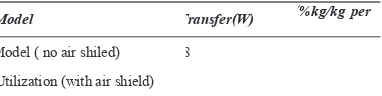
Both result of the model are summarizing in Table 1. In order to see the effectiveness of the model, dimensionless heat transfer could be obtained dividing base model with BOG utilization model which was lead to 0.43. Same value is expected for dimensionless BOR since linear relation is shown in Equation (1). This heat transfer interception will lead to BOG save for almost 60% by assuming that 100% efficiency of the heat exchanger.
Table 1 Heat Transfer and BOR comparison.
Model Transfer(W) (%kg/kg per
Model ( no air shiled) 8
Utilization (with air shield)
As shown in Figure 2, the distribution temperature on the shield plate inside insulation space are almost constant ranging from 130K to 140K. Inlet of the air floe through the plate are along z-axis with initial temperature 130K as explained before.
Flowrate of the air must be high enough to ensure lowest temperature distribution along the tank wall. However, higher flowrate will consume more energy. In this paper flowrate of 50m3/s are chosen which was will introduce turbulent behavior of the flow. In the model, Realizable K-Epsilon turbulent model are chosen due to its high reliability in solving fluid flow and heat transfer problem [16].
4.Conclusion
Heat transfer and fluid flow were numerically studied using the Computational Fluid Dynamic software, and the application of passive cooling by utilization cooled BOG to minimize the heat leakage and Boil off rate are examined in detail in this study.Full 3D model of 40447m3 LNG tank size for typical 160000m3 LNG GTT NO96 membrane type ship size are analyze to gain temperature distribution, heat leakage and BOR, then compare it with new proposed insulation system of the tank.
Result shows that the newly proposed system can minimize the BOG formation, thus prevent it from release and vented to the atmosphere which was have high impact to the environment, energy and economic.
Acknowledgements
The authors wish to thank UniversitiTeknikal Malaysia Melaka (UTEM) and Ministry of Higher Education (MOHE) Malaysia for supporting this research activity.
References
[1] Chang, D., T. Rhee, 2008. A study on availability and safety of new propulsion systems for LNG carriers, Reliability Engineerin g & System Safety 93(12), 1877-1885.1
[2] Kuver, M. C. Clucas and N. Fuhrmann, (2002). Evaluation of propulsion options for LNG carriers, Proccedings of GASTECH , Doha, Qatar.2 [3] Shin, Y. and Y. P. Lee, 2009. Design of a boil-off natural gas reliquefaction control system for LNG carriers, Applied Energy 86(1), 37-44.3
[4] Kwang Pil, C., M. Rausand, 2008. Reliability assessment of reliquefaction systems on LNG carriers, Reliability Engineering & System Safety 93(9), 1345-1353.4
[5] quefaction for Large
gs of the 1st Annual Gas Processing Symposium, 317-324.5
[6] Bruno Gervet (2007) Gas Flaring Emission Contributes to Global WarmingRenewable Energy Research Group Division of Architectur e and Infrastructure Luleå University of Technology SE-97187 Luleå, Sweden6
[7] Hasan, M. Zheng, M.A. Karimi, I.A., 2009. Minimizing Boil-Off Losses in Liquefied Natural Gas Transportation, Industrial & Engineering Chemistry Research. 48(21), 9571-9580.7
[8] Javier Romero and Ignacio Mosquera, 2005. Maritime Transportation and Exploitation of Ocean and Coastal Resources. Proceedings of the 11th International Congress of the International Maritime Association of the Mediterranean, 2, 883-8928
[9] Chen, H. C.,2011. CFD Simulation of Compressible Two Phase Sloshing Flow in a LNG Tank. Ocean System Engineering,1, 31-57. 9
[10]Gulru Babac, Altug Sisman, Tolga Cimen (2009). Two-dimensional thermal analysis of liquid hydrogen tank insulation. International Journal of Hydrogen Energy. 34,6357 636310
[11]Guyer. E. C. and Brownell, D. E.,1999. Handbook of Applied Design. (reprinted ed.): Taylor &Francis. 11
[12]Adom, E. Islam, S. Z. Ji, X.,2010. Modelling of BoilOff Gas in LNG Tanks A Case study. International Journal of Engineering and Technology, 2 (4) ,292 -29612
[13]Q. S.Chen ,J. Wegrzyn , and V. Prasad, 2004. Analysis of temperature and pressure changes in liquefied natural gas cryogenic tanks, Cryogenic, 44(10), 701-709. 13
[14]Frank Kreith and Mark Bohn, 2001. Principles of heat transfer. Brooks/Cole Publisher, University of Michigan 14 [15]Hofmann, A. 2004. Theory to boil-off gas cooled shields for cryogenic storage vessels, Cryogenics. 44(3),159-165.15