DESIGN OF A COMFORTABLE BUS PASSENGER SEAT
LIEW KEAN FEI
SUPERVISOR DECLARATION
“I hereby declare that I have read this thesis and in my opinion this report is sufficient in terms of scope and quality for the award of the degree of
Bachelor of Mechanical Engineering (Automotive)
Signature: ……….. Supervisor: ………..
DESIGN OF A COMFORTABLE BUS PASSENGER SEAT
LIEW KEAN FEI
This report is submitted in partial
fulfillment of the requirements for the award of a Bachelor of Mechanical Engineering (Automotive)
Faculty of Mechanical Engineering Universiti Teknikal Malaysia Melaka
DECLARATION
“I hereby declare that the work in this report is my own except for summaries and quotations which have been duly acknowledged.”
Signature: ………..
Author: ………..
iii
Special thanks
My Parents
My Family
My FYP Supervisor
My Seminar Panels
ACKNOWLEDGEMENT
First of all, I would llike to special thanks to my final year project supervisor, Ir. Dr. Tan Chee Fai. In the progress of this final year project, Ir. Dr. Tan had given me a lot of ideas and comments to help me to improve in my project. Besides, I really appreciate him to spend a lot of time to discuss and guide me in these 2 semesters until the final year project completed.
Besides, I would like to thank my parents and my family for giving me spirit support and financial support while I completing my final year project. I also want to wish my appreciation to all my course mates who discuss and recommend some solutions during I faced problems and brainstorming session.
v
ABSTRAK
ABSTRACT
vii
TABLE OF CONTENTS
CHAPTER TITLE PAGE
DECLARATION ii
DEDICATION iii
ACKNOWLEDGEMENT iv
ABSTRAK v
ABSTRACT vi
TABLE OF CONTENTS vii
LIST OF TABLES x
LIST OF FIGURES xi
LIST OF SYMBOLS xiv
LIST OF APPENDICES xv
INTRODUCTION 1
CHAPTER 1
1.1 Overview 1
1.2 Problem Statement 2
1.3 Objective 2
1.4 Scope 3
LITERATURE REVIEW 4
CHAPTER 2
2.1 Defining the Comfortable 4
2.2 History of Seat 6
2.3 Current Seat Design 8
2.4 Current Bus Seat Issue 11
2.7 Brainstorm 15
METHODOLOGY 17
CHAPTER 3
3.1 Introduction 17
3.2 Market Study 19
3.3 Brainstorming 19
3.4 Model Development 20
3.5 Documentation 21
SUBJECTIVE ASSESSMENT 22
CHAPTER 4
4.1 Subjective Evaluation On Bus Passenger Seat Comfort 22
4.2 Objectives 24
4.3 Methodology 24
4.3.1 Method 25
4.3.2 Survey Area 25
4.3.3 Survey Questions Structure 25 4.3.4 Method of Analyze Survey Results 26 4.3.5 Procedures of Survey Session 26
4.4 Results 28
4.4.1 Demographic Results 29 4.4.2 General Questions Results 30 4.4.3 Evaluation on Comfortable Level 31
4.5 Summary 35
CONCEPTUAL DESIGN 37
CHAPTER 5
5.1 Introduction 37
5.2 Design Methodology 38
5.3 Conceptual Design 39
ix
5.4.4 Conceptual Design 4 44
5.5 Concepts Evaluation 45
5.6 Summary 46
MATHEMATICAL AND NUMERICAL MODEL 47
CHAPTER 6
6.1 Mathematical Model 47
6.1.1 Air Cushion 47
6.1.2 Volume Flow Rate 52
6.2 Numerical Model 54
6.2.1 Main Program 54
6.2.2 Sub-Program 55
6.3 Model Validation 56
RESULT AND DISCUSSION 64
CHAPTER 7
7.1 Results 64
7.1.1 Weight 64
7.1.2 Air Cell Height 66
7.1.3 Air Cell Stiffness 67
7.1.4 Length of Orifice 68
7.1.5 Diameter of Orifice 69 7.1.6 Weight versus Air Cell Height 70 7.1.7 Weight versus Air Cell Stiffness 71
7.2 Discussion 72
CONCLUSION AND RECOMMENDATION 74
CHAPTER 8
8.1 Conclusion 74
8.2 Recommendation 75
REFERENCES 76
LIST OF TABLES
NO TITLE PAGE
4.1 The 5 points smiley scales 23
4.2 The summary of the demographic data 29 4.3 Comfortable level evaluation after 1 hour bus travelling 33 4.4 Comfortable level evaluation after 3 hours bus travelling 34 4.5 Comparison of mean value after 1 and 3 hours bus travelling 35 5.1 The description of the product requirements for bus passenger
seat 39
5.2 The morphology chart for bus passenger seat prototype 40 5.3 The weighted objective evaluation of prototype concepts 46 6.1 List of description for schematically model 49 6.2 List of constants value applied in model validation 56 6.3 Variables parameters used to validate model 56 6.4 Variables parameters changed in orifice 61 7.1 Summary of percentage pressure change rate with different
weights 70
7.2 Summary of percentage pressure change rate with different
xi
LIST OF FIGURES
NO TITLE PAGE
1.1 Air cushion seat
(Source: Roho, 2012) 1
1.2 Gel cushion seat
(Source: Geltec, 2012) 2
2.1 Pressure distribution of a seated person
(Source: Seigler, 2002) 5
2.2 Basic of seating unit
(Source: Peterson, 2007) 6
2.3 Karl benz car
(Source: Blair, 2008) 7
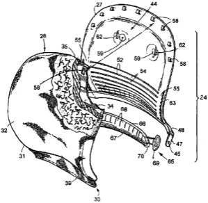
2.4 The V-shaped depression
(Source: Johnson, 1970) 8
2.5 The bus seat frame
(Source: Chardon, 1998) 9
2.6 The seat cushion structure
(Source: Michalak, 2012) 10
2.7 The BMW new car seat concept
(Source: Kamp, 2011) 10
2.8 Short distance bus seating
(Source: MYrapid, 2012) 11
2.9 Long distance bus seating
(Source: KKKL Sdn. Bhd., 2012) 12 2.11 The vehicle seat with inflatable air cushion
(Source: Awotwi et al., 1996) 14
2.12 Inflatable aircraft seat cushion
(Source: Duncan, 2003) 14
2.13 Contoured seat cushion
(Source: Graebe, 1991) 14
2.14 Example of the word map
(Source: Armstrong, 2006) 16
3.1 Flow chart of research activities 18
3.2 Brainstorming session 19
3.3 The solution for selected problem 20 3.4 The prototype of bus passenger seat 21
4.1 The smiley rating scales 26
4.2 Melaka Sentral Sdn. Bhd. 27
4.3 The interview-based method to approach bus passenger 28 4.4 Explanation terms and questions before answer survey questions 28 4.5 Pie chart showing percentage of types of bus seat take by bus
passengers 30
4.6 Pie chart showing estimated travelling duration take by bus
passengers 31
4.7 Comparison body discomfort for selected body parts 36 5.1 The total design process of bus passenger seat 39
5.2 The conceptual design 1 41
5.3 The exploded view for conceptual design 1 42
5.4 The conceptual design 2 42
5.5 The exploded view for conceptual design 2 43
5.6 The conceptual design 3 43
5.7 The exploded view for conceptual design 3 44
5.8 The conceptual design 4 44
5.9 The exploded view for conceptual design 4 45
xiii
6.2 The ROHO MOSAIC air cushion 48
6.3 The schematically model and free body diagram of two air cells 49 6.4 The flow in the orifice between 2 air cells with the average
velocity 53
6.5 The main program in MatLab SimuLINK 54 6.6 The sub-program to calculate the final conditions 55 6.7 (a) Pressure change for seated air cell in baseline case (b)
Pressure change rate for seated air cell in baseline case 57 6.8 (a) Pressure change for seated air cell in case 1 (b) Pressure
change rate for seated air cell in case 1 58 6.9 (a) Pressure change for seated air cell in case 2 (b) Pressure
change rate for seated air cell in case 2 59 6.10 (a) Pressure change for seated air cell in case 3 (b) Pressure
change rate for seated air cell in case 3 60 6.11 Volume flow rate for seated air cell in baseline case 61 6.12 Volume flow rate for seated air cell in case A 62 6.13 Volume flow rate for seated air cell in case B 63 7.1 Pressure change rate on the different bus passenger weight 65 7.2 Pressure change rate on the different air cell height 66 7.3 Pressure change rate on the different air cell stiffness 67 7.4 Volume flow rate on the different length of orifice 68 7.5 Volume flow rate on the different diameter of orifice 69 7.6 Comparison of different weight with increasing of air cell height 70 7.7 Comparison of different weight with increasing of air cell
stiffness 71
7.8 A comparison of weights on the Pcrms value by varying the cell height
LIST OF SYMBOLS
= Seated area of air cell, = Connected area of air cell,
= Diameter of orifice,
= Acceleration due to gravity,
= Air cell height,
= Air cell stiffness, ⁄
= Length of orifice,
= Pressure in seated air cell, = Pressure in connected air cell, = Initial pressure for air cushion model,
= Density of air, ⁄
= Dynamic viscosity,
= Time,
= Volume of seated air cell, = Volume of connected air cell,
= Vertical displacement of seated air cell, = Vertical displacement of connected air cell, = Weight of the seated person,
= Pressure change, = Pressure change rate,
xv
LIST OF APPENDICES
NO TITLE PAGE
A Gantt chart of PSM I 82
B Gantt chart of PSM II 83
C Conceptual Design Drawing 84
D Survey Approved Letter from UTeM 85 E Survey Approved Letter from Melaka Sentral Sdn. Bhd. 86
F Bus Passenger Seat Survey 88
CHAPTER 1
INTRODUCTION
1.1 OVERVIEW
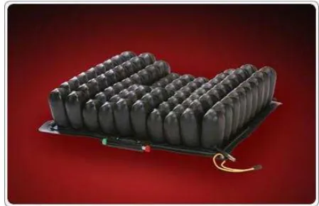
[image:18.595.205.430.440.585.2]In this research is design a comfortable bus passenger seat by integrating air based cushion and gel based cushion. The air cushion as shown in Figure 1.1 is designed with a recessed area to take the pressure off the tailbone and help eliminate back pain to provide hours of soft comfortable seating.
Figure 1.1: Air cushion seat (Source: Roho, 2012)
2
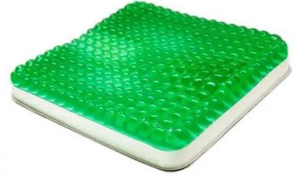
[image:19.595.210.423.150.288.2]seat will consider about the ergonomically shape to improve the Fit parameter levels of a bus passenger seat.
Figure 1.2: Gel cushion seat (Source: Geltec, 2012)
1.2 PROBLEM STATEMENT
Nowadays, most of the express coaches are using polyurethane foam based cushion in the seat padding. This type of the seat padding will cause a bus passenger who sit for long journey will feel uncomfortable and fatigue. There are two main causes which lead to uncomfortable and fatigue which is vibration of drive vehicle and pressure distribution on the seat. In this research will emphasize the integrated design of a bus passenger seat to ensure maximum comfort to the passenger.
1.3 OBJECTIVE
1. Study the current bus passenger seat and identify the product requirement on new design of bus passenger seat.
2. Design a bus passenger seat by using air-based and gel-based cushion to increase the comfortable level in the bus.
CHAPTER 2
LITERATURE REVIEW
2.1 DEFINING THE COMFORTABLE
The term of “seat comfort” is mean that the short-term effect of feeling of a seat on a human body. This will be the sensation usually appear during sitting on a seat for a short interval of time. The feel of “Comfort” is a vague or ambiguous concept and generally defined as lack of discomfort (Shen et. al., 1997).
In contrast, “driver fatigue” defines the physical impairments due to experience the seat dynamics for a long time. These uncomfortable condition are known in nature and include reducing in attention during driving, decision-making not correctly, reaction time slow down and vigilance (Seigler, 2002). For example, a tractor driver may exposure a lot of tension in physical and mental. The operator work performance will be very poor if the seat is not comfortable and there is also a possibility of accidents (Mehta et. al., 2007).
From this case shown that a comfortable seat is very important for a tractor operator but other consumer also very concern about this issue. The consumer expectations for a comfortable automobile seat keep increasing and the evident is the current automobile seat comfort development process. The automobile seat comfort is designed and came out with an ergonomics background which is developed in the field of applied science (Fazlollahtabar, 2010).
human physiology and biomechanics. The mechanisms of the seat comfort are including pressure distribution, thermal comfort, vibration transmissibility and other (Fazlollahtabar, 2010).
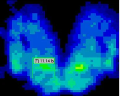
[image:22.595.218.421.358.521.2]Firstly, some of the researchers recommend that the pressure distribution will affects the perceptions of seat comfort. Pressure distribution at human-seat interface as shown in the Figure 2.1 is one of the important cause affecting the seating comfort and work efficiency of various worker (X. Wu, 1996). The appearance of the high pressure at the human-seat interface affect the soft tissue deformation leading to restricted blood and nutrient flows in the part of the body and bring discomfort to the human (Kumar et al., 1994). So, a seat with a good pressure distribution brings a suitable and balanced support to body areas during the contact on the seat.
Figure 2.1: Pressure distribution of a seated person (Source: Seigler, 2002)
6
Next, the vibration transmissibility in vertical direction is one of the most investigated objective measures of seat comfort. Human will experience the vibration to some degree in any transportation or moving vehicle which is car, truck, bus, train, airplane or boat. The frequency range of 2-6 Hz will bring the hazard to the human operator because the resonance occurs within this frequency range. Then, the design parameters improvement for tractor seats is needed to increase the reductions in the level of ride vibrations exposure by tractor operators (Prasad, 1995).
From the thesis related the term of “seat comfort” had shown that to design a comfortable seat must reduce the several performance measures based on physiology and biomechanics. The performance measures are more important and need to be studied will be pressure distribution, thermal comfort and vibration transmissibility.
2.2 HISTORY OF SEAT
[image:23.595.244.394.573.719.2]First of all, the seating unit is referring to a base and a seat support supported by the base. Usually, the structure for a seat is the back upright is function to support on the base for adjustment between an upright position and a reclined position (Peterson, 2007). On this seating unit, the cushion is position on the surface of the back support and the seat support. The cushions conduct a cushioning effect so that seated user’s body experienced the comfort when sit on the seating unit and the example of the seating unit as shown in the Figure 2.2 (Peterson, 2007).
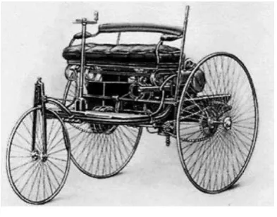
antique and collectible cars, Old Autos was recently described the earliest reference to an automotive seating type (Ontario, 2007). One of the article with title “The Benz patent motor car, No 1” is about the world’s first petroleum-based fuel vehicle in 1885. The bench seat of this Karl Benz Car as shown in Figure 2.3 is described as “horseless carriage” and “The padded, leather bench seat sat on springs mounted directly to the frame” (Ontario, 2007). After that moment, the construction of the automotive seat and the cushioning material employed to build up a more comfortable place for operators and the improvement on automotive seat have continued to evolve (Blair, 2008).
Figure 2.3: Karl benz car (Source: Blair, 2008)
Next, the seating cushion is very important for human who travelling because it can provide a comfortable seat in the vehicle. The ergonomic seating cushion has a central cavity and the interior boundaries form an oscillating waveform can provide a comfortable seat. It is because the feature had reduced the pressure gradient on skin pressing again the cushion, promoting blood flow to the region (Loomos, 2003).