i
ANALYSIS AND DESIGN OF HIGH GAIN AND LESS LOSS FOR MULTIBAND MICROSTRIP ANTENNA USING DEFECTED GROUND
STRUCTURE (DGS)
NUR NABILA BINTI PILI
This Report Is Submitted In Partial Fulfillment of Requirement for the Bachelor Degree of Electronic Engineering (Wireless Communication)
Fakulti Kejuruteraan Elektronik dan Kejuruteraan Komputer
Universiti Teknikal Malaysia Melaka
v
vi
ACKNOWLEDGEMENT
This research paper is made possible through the help and support from everyone, including the supervisor, parents, and friends. Especially, please allow me to dedicate my acknowledgment of gratitude toward the following significant advisor. I would like to thank PM Dr Badrul Hisham Bin Ahmad for his most support and encouragement. He kindly read my paper and offered invaluable detailed advices on organization, and the contents of the paper.
Secondly, I would like to thank the panels for PSM 1 and PSM 2, Dr Ho Yih Hwa and Encik Nor Azlan Bin Mohd Aris for comments that greatly improved the project and also the research paper. Not forgetting, a lot of thanks to my family for the moral and financial support until I manage to complete this project.
vii
ABSTRACT
viii
ABSTRAK
ix
TABLE OF CONTENT
CHAPTER CONTENT PAGE
PROJECT TITLE DECLARATION DEDICATION ACKNOWLEDGEMENT ABSTRACT ABSTRAK
TABLE OF CONTENT LIST OF TABLES LIST OF FIGURES
I INTRODUCTION
1.1 PROJECT BACKGROUND 1.2 PROBLEM STATEMENT 1.3 OBJECTIVES
1.4 PROJECT SCOPES
1.5 BRIEFLY EXPLANATION ON METHODOLOGY
1.6 METHODOLOGY 1.7 THESIS PLAN
x
II LITERATURE REVIEW
2.1 Introduction 7
2.2 Basic Operation of Microstrip Antenna 8
2.3 Feeding Technique 9
2.4 Important Parameter of Antenna 10
2.4.1 Return Loss 10
2.4.2 Gain 10
2.4.3 Bandwith 11
2.4.4 Radiation Pattern 11
2.4.5 Directivity 12
2.5 Advantages and Disadvantages of Microstrip Antenna 12 2.5.1 Advantages of Microstrip Antenna 12 2.5.2 Disadvantages of Microscrip Antenna 13 2.6 Defected Ground Structure (DGS) 13 2.7 Basic Ideas and Geometries 14
2.8 Past Work Research 15
III METHODOLOGY
3.1 Introduction 18
3.2 A Multiband Microstrip Antenna Design 18 3.2.1 Design Specification 19
3.3 Designs by Calculation 20
xi
IV RESULTS AND DISCUSSION
4.1 Original Design 24
4.1.1 Return Loss Original 25
4.1.2 Gain Original 26
4.2 Design with Circle DGS 27
4.2.1 Return Loss with circle DGS 27
4.2.2 Gain with circle DGS 29
4.3 Design with Dumbbell DGS 32
4.3.1 Return Loss with Dumbbell DGS 32
4.3.2Gain with dumbbell DGS 34
4.4 Design with Square DGS 37
4.4.1 Return Loss with circle DGS 37
4.4.2 Gain with square DGS 39
4.5 Fabricated Antenna 42
4.6 Measurement 42
4.6.1 Return Loss 42
4.6.2 Gain 44
4.7 The Comparison between the Simulated and 44 Fabricated Antenna
4.7.1 Return Loss 45
xii
V CONCLUSION AND RECOMMENDATION
5.1 Conclusion 47
5.2 Future Work 48
xiii
LIST OF TABLES
NO TITLE PAGE
4.1 Return Loss for Original Antenna 25
4.2 Comparison of return loss with two, four and six circle DGS 28 4.3 Comparison of return loss with two, four and six dumbbell DGS 33 4.4 Comparison return loss with two, four and six square DGS 38 4.5 Measured return loss for original antenna 43 4.6 Measured return loss for antenna with six circle DGS 43 4.7 The Comparison of original return loss between 45
simulation and measurement result
4.8 The Comparison of return loss with six circle DGS between 45 simulation and measurement result
4.9 The Comparison of original gain between simulation 46 and measurement result
xiv
LIST OF FIGURES
NO TITLE PAGE
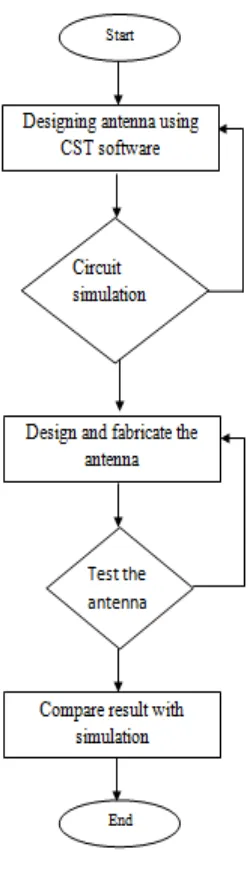
1.1 Flow chart of the project 5
2.1 Basic structure of a microstrip patch antenna 7
2.2 A side view of microstrip patch antenna 8
2.3 Inset feed line 9
2.4 Spherical coordinate systems for antenna analysis 11
2.5 Various type of DGS geometries 14
3.1 Design for multiband antenna (front view) 19
3.2 Shapes for DGS 19
3.3 Background properties 22
3.4 Substrate material properties 23
3.5 Monitor Setting 23
4.1 Original design (a) front (b) back 24
4.2 Graph of Return Loss for Original Antenna 25 4.3 Gain for original design at frequency of 4.65GHz 26 4.4 Gain for original design at frequency of 6.871GHz 26 4.5 Gain for original design at frequency of 9.723GHz 26 4.6 Design with 2, 4 and 6 Circle DGS 27
4.7 Return loss of two circle DGS 27
4.8 Return loss for four circle DGS 27
4.9 Return loss for six circle DGS 28
xv
4.11 Gain for design with 2 circle DGS at frequency of 4.65GHz 29 4.12 Gain for design with 2 circle DGS at frequency of 6.871GHz 29 4.13 Gain for design with 2 circle DGS at frequency of 9.723GHz 29 4.14 Gain for design with 4 circle DGS at frequency of 4.65GHz 30 4.15 Gain for design with 4 circle DGS at frequency of 6.871GHz 30 4.16 Gain for design with 4 circle DGS at frequency of 9.723GHz 30 4.17 Gain for design with 6 circle DGS at frequency of 4.65GHz 31 4.18 Gain for design with 6 circle DGS at frequency of 6.871GHz 31 4.19 Gain for design with 6 circle DGS at frequency of 9.723GHz 31 4.20 Design with 2, 4 and 6 Circle DGS 32
4.21 Return loss of two dumbbell DGS 32
4.22 Return loss of four dumbbell DGS 32
4.23 Return loss of six dumbbell DGS 33
4.24 Comparison of return loss with two, four and six circle DGS 33 4.25 Gain for design with 2 dumbbell DGS at frequency of 4.65GHz 34 4.26 Gain for design with 2 dumbbell DGS at frequency of 6.871GHz 34 4.27 Gain for design with 2 dumbbell DGS at frequency of 9.723GHz 34 4.28 Gain for design with 4 dumbbell DGS at frequency of 4.65GHz 35 4.29 Gain for design with 4 dumbbell DGS at frequency of 6.871GHz 35 4.30 Gain for design with 4 dumbbell DGS at frequency of 9.723GHz 35 4.31 Gain for design with 6 dumbbell DGS at frequency of 4.65GHz 36 4.32 Gain for design with 6 dumbbell DGS at frequency of 6.871GHz 36 4.33 Gain for design with 6 dumbbell DGS at frequency of 9.723GHz 36 4.34 Design with 2, 4 and 6 Square DGS 37
4.35 Return loss of two square DGS 37
xvi
4.37 Return loss of six square DGS 38
1
CHAPTER 1
INTRODUCTION
This chapter will discuss briefly about the background the problem statement, objectives and scope of the project that have been chosen.
Multiband antenna is an antenna designed to operate on several bands. A multiband antenna may have lower than average gain or may be physically larger in compensation.
DGS is realized by introducing a shape defected on a ground plane which disturbs the current distribution of the antenna [7]. The disturbance at the shielded current distribution will influence the input impedance and the current flow of the antenna. Shapes and number of DGS also affect the performance of the antenna.
2
1.1 Project Background
This project proposed to analysis and design of high gain and less loss for multiband microstrip antenna using defected ground structures (DGS). Recently there has been much interest in microstrip patch antenna because of its simplicity and compatibility. Because of their advantages in simplicity and compatibility with printed circuit technology, microstrip antennas are widely used in the wireless telecommunication systems [2]. These types of antennas are attractive in antenna applications for many reasons such as they are easy and cheap to manufactured and also light in weight.
While using microstrip patch antenna the other problems which will occurs are high loss and surface wave in substrate layer, as the losses will always occurs in radiation as the antenna is transmitting the signals. Due to surface wave radiation excitation losses occur that will cause decrease in the antenna efficiency, gain and bandwidth because the surface wave occurs, it extract total available power for radiation to space wave [3].
1.2 Problem Statement
3
1.3 Objectives
The objectives of the project are:
1. To study the effect of different number and shapes of DGS toward improvement of gain and return loss in antenna
2. To design an antenna with implement of DGS at three operating frequency range from 3GHz to 10GHz
3. To fabricate the proposed antenna and conduct the experiment test on it.
1.4 Project Scopes
4
1.5 Brief Explanation on Methodology
The suitable software is the first thing needed consideration in order to design the antenna. CST Studio Suite Software is the most common and user-friendly software to design antenna. The software enables users to design the desired antenna in 3D version that will give a clearer vision about the sooner fabricated antenna. By using this CST software, the users are able to do the simulation after designing the antenna. The simulation result will measure and display the various parameters such as gain, return loss, directivity bandwidth and so on. After getting the desired simulation result, the next step which is fabrication step will be proceed. In the fabrication step, the designed antenna will be fabricated on the FR4 substrate. After finish the fabrication step, then the test will be held upon the antenna by using the facilities and equipment provided in the lab at Universiti Teknikal Malaysia Melaka.
1.6 Methodology
5
6
1.7 Thesis Plan
This thesis will be divided into five chapters.
Chapter 1- This chapter will briefly explained about the introduction and the background of the project. Some information about the type of antenna used is also mentioned. This chapter also includes the problem statement, objectives and project scope and brief explanation on methodology.
Chapter 2- This chapter is about the literature review about this project will be reviewed. It includes the explanations of the past work research related to this project. The past research will be based on the high gain and less loss multiband antenna. Chapter 3- This chapter is about methodology. It will explain in details the methods and procedures as the guideline to complete and run the project perfectly from the beginning till the end.
Chapter 4- This chapter will present all the tabulation data and results. The discussion about this project will be included in this chapter instead.
7
CHAPTER 2
LITERATURE REVIEW
This chapter will explained on the fundamental concept and theory of multiband antenna with DGS base on past work research. The information gathered in this literature review chapter can be a guideline in designing and simulating the proposed antenna in the correct way so it may work perfectly according to plan. Most of the past study discussed about almost the same good features of multiband antenna that will achieve in a way desired.
2.1 Introduction
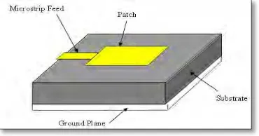
[image:23.595.227.412.635.732.2]A microstrip patch antenna is a narrowband wide beam antenna fabricated by etching the antenna element pattern in metal trace bonded to an insulating dielectric substrate, such as a printed circuit board, with a continuous metal layer bonded to the opposite side of the substrate which form a ground plane [4]. The conducting patch can take any shape but rectangular and circular shapes are commonly used.
8
2.2 Basic Operation of Microstrip Antenna
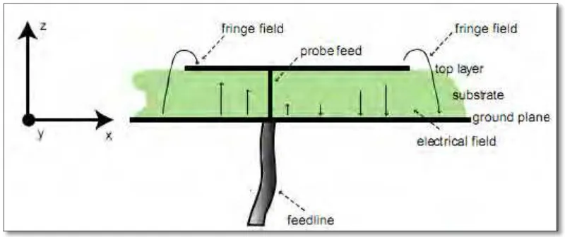
[image:24.595.115.515.217.385.2]The figure below shows a patch antenna in its basic form which consist a flat over a ground plane. The center conductor of a coax serves as the feed probe to couple electromagnetic energy in and/or out of out of the patch. The electric field distribution of a rectangular patch excited in its fundamental mode is also indicated [5].
Figure 2.2: A side view of microstrip patch antenna
The electric field is zero at the center of the patch, maximum at one side, and minimum on the opposite side. It should be mentioned that the minimum and maximum continuously change side according to the instantaneous a cavity. Rather, the fields extend the outer periphery to some degree. These field extensions are known as fringing fields and cause the patch to radiate. Some popular analytic modeling techniques for patch antennas are based on this leaky-cavity concept. Therefore, the fundamental mode of rectangular patches often denoted using cavity theory as the TM10 mode.
TM stands for transversal magnetic field distribution. This means that only three field components are considered instead of six. The field components of