I
FAKULTI KEJURUTERAAN ELEKTRIK
LAPORAN PROJECT
SARJANA MUDA
DESIGN AND DEVELOPMENT OF MOTOR
CONTROL USING EMG-FORCE SIGNAL
CHOOI KAH YUNG
Bachelor of Mechatronics Engineering
II
“ I hereby declare that I have read through this report entitle “Design and development of
motor control using EMG-force signal” and found that it has comply the partial fulfilment
for awarding the degree of Bachelor of Electrical Engineering (Mechatronics Engineering)”
Signature : ...
Supervisor’s Name : ...
I
DESIGN AND DEVELOPMENT OF MOTOR CONTROL USING EMG-FORCE
SIGNAL
CHOOI KAH YUNG
A report submitted in partial fulfilment of the requirements for the degree
of Bachelor of Mechatronics Engineering
Faculty of Electrical Engineering
UNIVERSITI TEKNIKAL MALAYSIA MELAKA
II
I declare that this report entitle “Design and development of motor control using
EMG-force signal” is the result of my own research except as cited in the references. The report has not been accepted for any degree and is not concurrently submitted in candidature of any other degree.
I
II
ACKNOWLEDGEMENT
In preparing this report, besides searching for related article and journal, I also get in contact with many people inside my University, including lecturers, researchers and colleagues. I have learned many knowledge and they have greatly contributed to me by triggering the new ideas. I wish to express my sincere appreciation to my main project supervisor, Dr. Muhammad Fahmi bin Miskon and my friend Mohammad Ihsan bin Sabri. They has helps me a lot by giving me suggestion, opinion and guidance, helping me finish this report..
III
ABSTRACT
IV
ABSTRAK
IV
THEORETICAL BACKGROUND AND LITERATURE REVIEW 5
2.1 Theory of motor control using EMG-force signal 5
2.1.1 Electromyography (EMG) signal 6
V
2.1.3 Surface EMG data collection 7
2.1.4 Feature extraction and Pattern Recognition 9
2.1.5 Model of Human Upper Arm 11
2.1.6 Motor Actuator Control 13
2.2 Problems of DC motor control using EMG-force signal 15
3.1 Mapping of joint angle and surface EMG signal 23
3.2 Validation of idea 23
3.2.1 Objectives 24
3.2.2 Experiment Setup 24
3.2.2.1 Experiment 1: The relationship between EMG signal and elbow
joint angle with load and without load. 25
3.2.2.2 Experiment 2: The relationship between EMG signal and joint angle
for 4 respondents 28
3.2.2.3. Experiment 3: Testing the performance and absolute error of
designed Arduino program under non-fatigue condition. 30
3.2.2.4 Experiment 4: Identify and improve the error in DC motor with
encoder 31
3.2.3 Development of prototype for validation 32
3.2.4 Method of Analysis 37
Chapter 4 39
RESULT, ANALYSIS AND DISCUSSIONS 39
4.1 Experiment 1: The relationship between EMG signal and elbow joint angle
VI
4.2 Experiment 2: The relationship between EMG signal and joint angle for 4
respondents 43
4.3 Experiment 3: Testing the performance and absolute error of Arduino
program under non-fatigue condition 52
4.4 Experiment 4: Identify and improve the error in DC motor with encoder 64
CHAPTER 5 69
CONCLUSIONS 69
5.1 Conclusions 69
5.2 Suggestions and future work 70
REFERENCES 72
Appendices 75
Appendix A: List of item 75
Appendix B: Overall Circuit 76
Appendix C: flow chart and programming code for experiment 1 77
Appendix D: Data about respondents in this thesis 79
Appendix E: Flow chart and coding for program in experiment 3 80
VII
LIST OF TABLE
TABLE TITLE PAGES
Table 1: Comparison among variable solution ... 18
Table 2: Actual and calculated moving average value for respondent A ... 47
Table 3: Actual and calculated moving average value for respondent B ... 48
Table 4: Actual and calculated moving average value for respondent C ... 49
Table 5: Actual and calculated moving average value for respondent D ... 50
Table 6: Performance of the program for respondent A ... 56
Table 7: Performance of program for respondent D... 57
Table 8: Performance of program for respondent E ... 59
Table 9: Performance of program for respondent F ... 61
Table 10: Percentage of encoder error vs desired angle ... 65
VIII
LIST OF FIGURES
FIGURE TITLE PAGES
Figure 1: Exoskeleton robot training device ... 2
Figure 2: Block diagram of motor control using EMG-Force signal ... 5
Figure 3: Raw EMG signal... 6
Figure 4: Biceps brachii muscle ... 8
Figure 5: Location of electrodes for biceps brachii ... 9
Figure 6: The relationship between EMG, joing angle and torque ... 10
Figure 7: Model of human arm under different joint angle ... 11
Figure 8: Isometric torque vs joint angle ... 12
Figure 9: Anterior deltoid muscle ... 12
Figure 10: Circuit of shunt dc motor ... 13
Figure 11: Speed torque characteristics ... 14
Figure 12: Block diagram with material... 22
Figure 13: Position of signal and reference electrode ... 26
Figure 14: Position of ground electrode ... 26
Figure 15: Sensor arduino circuit ... 26
Figure 16: Board for position guiding ... 27
Figure 17: Isometric contraction ... 27
Figure 18: Exoskeleton Mechanism ... 28
Figure 19: Setup of equipment together with respondent ... 29
Figure 20: Isometric contraction on 70 degree ... 30
Figure 21: Setup of circuit with LCD ... 30
Figure 22: Setup of DC motor and protractor ... 31
Figure 23: G203 disposable electrode ... 32
Figure 24: Muscle sensor v3 kit and its circuit connection ... 33
Figure 25: Example of output signal from sensor ... 33
Figure 26: Voltage regulator ... 34
IX
Figure 28: LCD keypad shield ... 35
Figure 29: Driver L298 ... 35
Figure 30: Driver circuit ... 36
Figure 31: DC gear motor and encoder state ... 36
Figure 32: Moving average and RMS vs time for unloaded 40 degree ... 39
Figure 33: Moving average vs angle for unloaded condition ... 41
Figure 34: Modified RMS vs angle for unloaded condition ... 41
Figure 35: Moving average vs angle for loaded condition ... 42
Figure 36: Modified RMS vs angle for loaded condition ... 42
Figure 37: Moving average vs angle for respondent A ... 44
Figure 38: Moving average vs angle for respondent B ... 44
Figure 39: Moving average vs angle for respondent C ... 45
Figure 40: Moving average vs angle for respondent D ... 45
Figure 41: Actual and calculated moving average value for respondent A ... 47
Figure 42: Actual and calculated moving average value for respondent B ... 48
Figure 43: Actual and calculated moving average value for respondent C ... 49
Figure 44: Actual and calculated moving average value for respondent D ... 50
Figure 45: Moving average vs angle for all respondent ... 51
Figure 46: Screen of LCD when calibrate 20 degree in calibration 1 mode ... 53
Figure 47: Screen of LCD when viewing the saved moving average ... 53
Figure 48: Graph of moving average vs angle with a turning point ... 54
Figure 49: Screen of LCD when in running mode ... 55
Figure 50: Moving average vs angle for respondent A ... 56
Figure 51: Average absolute error of calibration 1 & 2 for respondent A ... 57
Figure 52: Moving average vs angle for respondent D ... 58
Figure 53: Average absolute error of calibration 1 & 2 for respondent D ... 58
Figure 54: Moving average vs angle for respondent E ... 60
Figure 55: Average absolute error of calibration 1 & 2 for respondent E ... 60
Figure 56: Moving average vs angle for respondent F ... 61
Figure 57: Average absolute error of calibration 1 & 2 for respondent F ... 62
Figure 58: Average absolute error for calibration 1 & 2 for all respondents ... 64
Figure 59: Encoder states of the DC motor ... 65
Figure 60: Percentage of error vs angle ... 66
Figure 61: Encoder pulse vs time ... 68
X
LIST OF SYMBOLS
N - Sample size
VT - Terminal voltage
EA - Induced voltage
IA - Armature current
RA - Armature resistance
k - Constant
ω - Angular velocity
ϕ - Magnetic flux
τ - Torque
F - Force
r - Radius
m - Mass
g - Gravitational force, 9.81 m/s
XI
LIST OF APPENDIX
APPENDIX TITLE PAGES
Appendix A: List of item ... 75
Appendix B: Overall Circuit ... 76
Appendix C: flow chart and programming code for experiment 1 ... 77
Appendix D: Data about respondents in this thesis ... 79
Appendix E: Flow chart and coding for program in experiment 3 ... 80
1 stroke is the third largest cause of death in Malaysia[1]. Every year, there is estimate 40000 people suffer from stroke. One of the effects of stroke is the disability of certain part of body and it depends on which part of the brain is damaged. Based on the stroke statistics from University hospital, New Jersey, stroke is the main cause of disability among adults
in US[2]. Rehabilitation needed to be done to improve patient’s body function so that they
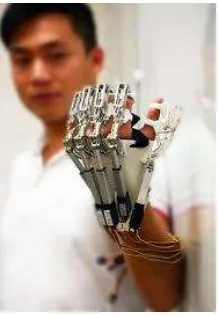
can become independent to the other. Nowadays, therapist can get help from artificial device in rehabilitation process. Human exoskeleton interaction can be done in 3 methods. The first method is by brain activity or Electroencephalography (EEG), the second method is using muscle signal or Electromyography (EMG). The last method is generation of the assisting exoskeleton movements.
2
Figure 1: Exoskeleton robot training device
1.2 Problem Statement
The characteristic of EMG signal should be studied before it could be applied to control the rotation of a motor. Information like joint angle and torque can be obtained in EMG signal. However different people will have different muscle firing frequency, ratio of slow to fast-switch fibre, fatigue status and muscle unit, hence the EMG signal can’t directly compare across the subjects. To control the position of the motor, the relationship between the EMG signal, torque and position have to be study before using it to control the motor actuator.
Researched questions are described as below:
a) What are the available features that could provide the most accurate and easiest mapping between EMG-force signal and joint angle?
3
1.3 Project Objectives
The objectives of this project are defined as below:
a) To study the relationship between joint angle, torque and EMG-force signal
b) To synchronize the rotation angle of motor and elbow joint angle by
mapping EMG-force signal from biceps brachii muscle.
1.4 Scope of the Project
The scopes of works are described as below
a) 4 respondents are selected for experiment 2 and 3. All EMG signal are
retracted from biceps brachii muscle in right arm by using disposable surface electrode.
b) All experiments are carried under minimum fatigue condition. The
experiments are focused on isometric contraction (static position).
c) The rotation angle of DC motor actuator and elbow joint angle is limit from
0 to 90 degreeonly.
1.5 List of Contribution
The contribution of this thesis is:
a) Development of a new mapping method that can accurate synchronizes and
maps the joint angle and EMG signal in real time and suitable for different user.
b) Development of a new method to control a DC motor by using human arm
motion.
1.6 Outline of Dissertation
4
5
CHAPTER 2
THEORETICAL BACKGROUND AND LITERATURE REVIEW
2.1 Theory of motor control using EMG-force signal
This section introduces the EMG signal, signal processing, Surface EMG (SEMG) collection, feature extraction, pattern classification and model of human upper limb. Figure 2 shows the block diagram of actuator control system using EMG-force signal.
6
2.1.1 Electromyography (EMG) signal
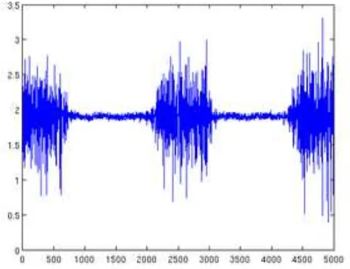
Electromyography (EMG) refers to recording of muscle’s electric activities [5]. It also is an experimental technique concerned with the development, recording and analysis of myoelectric signals. Figure 3 shows the raw EMG signal during muscle contraction.
Figure 3: Raw EMG signal
Myoelectric signals are formed by physiological variations in the state of muscle fibre membranes. The amplitude of EMG signal is depends on the muscle contraction. The stronger the contraction of the muscle, the higher the amplitude of EMG produced by that muscle. Dynamic action like rotating joint angle or static action like holding the load can increase our muscle contraction. Other than that, the shape and amplitude of EMG also depends on amount of motor unit and firing rate, hence different people will have different amplitude and shape of EMG signal.
2.1.2 Signal Processing
Since raw EMG signal has very low voltage, typical EMG electric potentials is between 50 µV up to 20 or 30 mV in amplitude[6]. Practical EMG signal contains some noise due to the influence of electronic component and the electric power cable, it has to go through signal processing unit before we can process it. Raw EMG signal has to amplifier, go through band pass filter to filter the noise. Normally frequency of surface EMG ranged from 0-500Hz, but only 50-150Hz is the useable energy[7]. Controller like
7
process, the entire negative signal have to be eliminated. There are 2 methods to eliminate the negative signal, one is by full rectification process, and the other one is by adding offset voltage into the signal to neutralize the negative signal [8].
2.1.3 Surface EMG data collection
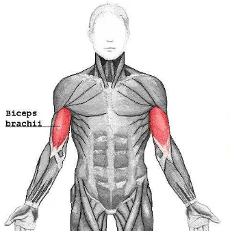
EMG signals are measured within the muscle tissue itself or at the external derma by means of either needle or surface electrodes. Electrodes are sensors that detect electrical potential generated inside the nerves and muscles[9]. Even though EMG signal which recorded by needle is more accurate than surface electrodes, however modern researcher more prefer to surface electrodes as it is more convenient and bring no pain to respondents. There are 2 types of electrode that can be used to capture the surface EMG signal, unipolar electrode and bipolar electrode. Unipolar electrode is a type of electrode which only requires one electrode to capture the signal. For the bipolar electrode, it requires 2 electrodes, 1 of the electrode placed in the centre of the muscle to capture the muscle signal while another electrode placed in the end of muscle to acts as the reference point. The output is the difference of voltage level between those 2 electrodes.
The high impedance between our skins and surface electrode will weaken the signal received by electrode. To improve the performance of the surface electrode, the skin surface should be watch and cleaned using alcohol. Hair should be shaved to increase the touching area between the surface electrode and our skin.[10] Electrolytic gel like silver chloride gel is used to improve the contact between the electrode and the skin, it act as the medium to easier the transfer of electrons from skin to electrode.
8
Figure 4: Biceps brachii muscle