i
“I hereby declare that I have read through this report entitle “Design and development of small-scale regenerating energy using brush DC motor” and found that it has comply the partial fulfilment for awarding the degree of Bachelor of Electrical Engineering (Power
Electronic & Drives)”
Signature : ………
Supervisor’s Name : ……….
ii
DESIGN AND DEVELOPMENT OF SMALL-SCALE REGENERATING ENERGY USING BRUSH DC MOTOR
SUTHAKARAN S/O SOLAMUTHU
A report submitted in partial fulfilment of the requirement for the degree of Bachelor of Electrical Engineering (Power Electronic & Drives)
Faculty of Electrical Engineering
UNIVERSITI TEKNIKAL MALAYSIA MELAKA
iii
I declare that this report entitle “Design and development of small-scale regenerating energy using brush DC motor” is the result of my own research except as cited in references. The report has not been accepted for any degree and is not concurrently
submitted in candidature of any other degree.
Signature : ………
Name : ……….
iv
DEDICATION
First of all, I would like to thanks God because able to complete this project and fulfil the requirement for Bachelor of Electrical Engineering (Power Electronic & Drives) successfully.
I was in contact with many people in the midst of preparing this report especially my beloved mother and sister. They have contributed toward my thought and advices. I’m grateful to my mother who had supported and cheered me all the way during my completion of this final project and also during my studies in University Teknikal Malaysia Melaka (UTeM). And not to forget about my sister who had contributed toward my knowledge and support me by financially. And more over she had given advices and ideas to complete this report successfully.
v
ACKNOWLEDGEMENT
In preparing this report, I was in contact with many people, researcher s, academicians and practitioners. They have contributed towards my understanding and thought. In particular, I wish to express my sincere appreciation to my main project supervisor, Mr Mohd Saifuzam Bin Jamri. Under his supervision, many aspects regarding this project have been explored and with this knowledge, idea and support received from him, this report can be presented in time given.
I am also very thankful to Master students that have helped me in term of technical support. Through their guide in term of technical I have succeed finishing by circuit and error that I have faced. I also extend my appreciation and thanks for lectures those who had directly or indirectly helped me undergo this project.
vi
ABSTRACT
vii
ABSTRAK
viii
TABLE OF CONTENTS
CHAPTER TITLE PAGE
DEDICATION iv
ACKNOWLEDGEMENT v
ABSTRACT vi
TABLE OF CONTENTS viii
LIST OF TABLE x
LIST OF FIGURES xi
LIST OF APPENDICES xiii
1 INTRODUCTION
1.1 Background and motivation 1
1.2 Problem statment 2
1.3 Project objective 3
1.4 Scopes / Limitations 3
2 LITERATURE REVIEW
2.1 Implementation and Performance 4
2.2 Braking power analysis 5
2.3 Energy Capturing Devices 5
2.4 Ultra-capacitors 6
2.5 PWM controlling technique 7
2.6 Journal review 7
2.7 Power MOSFET 11
2.8 SG3526 IC 12
2.9 Convertor in electric drive system 14
ix
CHAPTER TITLE PAGE
2.11 Conclusion 19
3 METHODOLOGY
3.1 Project methodology 20
3.2 Project development 25
3.3 Flow chart explanation 27
3.4 Design system 32
3.4.1 Boost Converter 32
3.4.2 Super-capacitor circuit 39
4 RESULT AND DISCUSSION
4.1 Result 46
4.1.1 Boost convertor discussion 47
4.2 Power consumption result 50
4.2.1 Before restructured result 51 4.2.2 After restructured result 53
4.2.3 Graph comparison 55
4.2.4 Data and graph analysis 56
4.3 Simulation result 57
5 CONCLUSION AND RECOMMENDATION
5.1 Conclusion 64
5.2 Recommendation 65
REFERENCES 66
x
LIST OF TABLES
TABLE TITLE PAGE
Table 2.1 Forward diode voltage range 12
Table 3.1 Testing template 22
Table 4.1 Boost converter result 47
Table 4.2 Before restructured table result 51
xi
LIST OF FIGURES
FIGURE TITLE PAGE
Figure 2.1 Forces acting on a vehicle while braking on level
ground 5
Figure 2.2 Ultra-capacitor layout 6
Figure 2.3 Three-phase inverter and brushless DC motor 8
Figure 2.4 Structure sketch of implied equivalent circuit of
duplex energy storing system 10
Figure 2.5 MOSFET symbol 11
Figure 2.6 MOSFET schematic 11
Figure 2.7 SG3526 IC 13
Figure 2.8 SG3526 pin no 13
Figure 2.9 SG3526 block diagram 13
Figure 2.10 Oscillator Period Graph 14
Figure 2.11 Four quadrant operation mode 16
Figure 3.1 Flowchart to illustrate the project 20
Figure 3.2 Purpose matted block diagram 21
Figure 3.3 Electrical remote control car 22
Figure 3.4 Flow chart of process involved in regenerative
energy storing system 25
Figure 3.5 Ni-MH rechargeable battery 26
Figure 3.6 ESC controller switch 27
Figure 3.7 HL Sprint 3-channel AM Radio transmitter 27
Figure 3.8 FM Receiver 28
Figure 3.9 Super-capacitor 29
Figure 3.10 Inductor 33
Figure 3.11 Power MOSFET 33
xii
Figure 3.13 Osillator Period 35
Figure 3.14 Polarity capacitor 35
Figure 3.15 Boost convertor circuit diagram 38
Figure 3.16 Boost converter circuit 38
Figure 3.17 Super-capacitor circuit 39
Figure 3.18 Super-cap circuit diagram 40
Figure 3.19 RCSwitch10 and connection diagram 41
Figure 3.20 SC Function flow 42
Figure 3.21 Designing flow 1 43
Figure 3.22 Designing flow 2 43
Figure 3.23 Designing flow 3 44
Figure 3.24 Overall system diagram 45
Figure 4.1 Boost converter result graph 48
Figure 4.2 Oscilloscope captured graph 49
Figure 4.3 Technique used to collects data for boost converter 49
Figure 4.4 Trek 50
Figure 4.5 Power consumption before reformation 52
Figure 4.6 Speed performance before reformation 52
Figure 4.7 Power consumption after reformation 54
Figure 4.8 Speed performance after reformation 54
Figure 4.9 Power comparison before and after reformation 55
Figure 4.10 Speed comparison before and after reformation 55
Figure 4.11 Simulation block diagram 57
Figure 4.12 Used battery current 58
Figure 4.13 Motor speed 58
Figure 4.14 Motor armature current 59
Figure 4.15 Motor torque 59
Figure 4.16 Adapted simulation block diagram 60
Figure 4.17 Battery usage current after altered 60
Figure 4.18 Motor speed after altered 61
Figure 4.19 Motor armature current after altered 61
xiii
LIST OF APPENDICES
APPENDIX TITLE PAGE
A1 SG3526 DATASHEET 68
A2 IRF510 DATASHEET 77
1
CHAPTER 1
INTRODUCTION
1.1Background and motivation
Regenerative braking is one of the unusual technologies for electric vehicle. It serves to convert part of mechanical energy as known as kinetic energy into electric energy during braking. This energy can be stored in device for EV improvement. So regenerative braking plays an important role in reducing the energy consumption of EV. It also will increase the driving range and improve its performance. There are many research done about regenerative braking and different type of matted have been proposed.
This technology mostly used in car because the traditional braking system always use mechanical friction to split the kinetic energy as heat energy cause of stopping. When operating a vehicle, one third to one half of energy been use by the vehicle during braking. The kinetic energy is an excessive energy when the electric motor is in the braking state since it dissipated the energy and causes a loss of the overall energy. This wasted energy can be converted to useful energy.
This project motivate due to energy crisis in electric vehicle EV that had lot of issues on power consumption. This system is designed to improve the issues on power consumption and overall increase the performance of EV. From this improvement the usage of power to charge can be lest and can save and reduce the power losses.
2 will be used to improve the performance is by using an ultra-capacitor. This ultra-capacitor will be used to store the wasted energy when regenerative braking and utilize the energy back to motor. By this behave, the usage of battery power will be lesser and the torque performance of the motor will be increased.
1.2Problem Statement
In order to start up a brush DC motor, it requires a higher current for the armature to increase the torque performance. When the torque performance increase the speed will increase too. Each time the motor run in forward condition, a higher amount of current will be produce at the armature of the motor where this current been engaged from the power supply (battery). Each time the battery delivers a higher current, it will lose a bigger among of power. This will make the battery energy drop faster.
In order to solve this problem a system had been design to reduce the usage of power supply and further more increase the performance of the brush DC motor. This system work by storing the generated power by the DC motor when the motor act as generator into a ultra-capacitor. Then, this energy will be used when each time the start forward button been press. This energy will support to reduce the higher usage of starting current and also increase the torque performance when start up the motor that had been explained more detailed in chapter 4 (result and discussion).
3
1.3Project Objectives
The objective of this project is to develop small-scale regenerating energy using brushed DC motor that will have following abilities and properties:
i) Identify the suitable connection for ultra-capacitor in the circuit.
ii) Development of small-scale regenerating energy using brush DC motor
iii) Reduce the fast battery energy drain when staring the brush DC motor and increase
energy efficiency to battery life last long.
iv) Improve the torque and speed performance.
1.4Scopes/Limitations
As this project purpose was to design and develop a regenerating energy, it will be only cover on:
i) A small scale electric remote control car will be used based on the modular design
to repower an electric vehicle to implement this project.
ii) Do analysing and simulation on the torque performance (speed) before and after completing this project by using MATLAB.
iii) Calculate the rated value of ultra-capacitor that going to be used.
iv) Analysis the amount of energy and current produced by the brush DC motor when
it acts as generator (regenerating breaking).
v) Review the amount of voltage losses before and after completing this project.
vi) Observe the performance of the car before and after completing this project by derive a graph speed VS time.
4
Chapter 2
LITERATURE REVIEW
Literature review has been taken place on the beginning of the project as it started. The purposes of this process are to searches and gather the knowledge and information needed to ensure that the project will progress smoothly and successfully. This process was help continuously until the completion of this project since the information and knowledge are always needed throughout the development of this project. There are several important parts need to be researched to ensure the functionality of the system. Every important part in this researched based on theories, journal or thesis from past researchers.
2.1 Implementation and Performance Evaluation of a Regenerative Braking System Coupled to Ultra-capacitors for a Brushless DC Hub Motor Driven Electric Tricycle by Kuruppu, Sandun
5
2.2 Braking power analysis
The research mainly forces on the way how the vehicles produce energy and ability to recover it via regenerating breaking. It’s also including the weight of the vehicles and the way of handling capability of the electrical system.
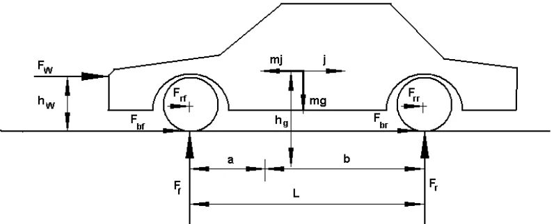
Figure 2.1: Forces acting on a vehicle while braking on level ground
j = the deceleration of the vehicle Fw = the aerodynamic resistance fr = the tire rolling resistance r = tire radius,
Fbr & Fbf = rolling resistances on the rear and front wheels respectively Instantaneous Energy = ½*m* …………[1]
6
2.3 Energy Capturing Devices
There are a lot of different types of battery able to store energy, include lead acid, Li –ion, Li polymer and Nikel Cadmium. Electrical energy storage is few used in electrical vehicles. Each battery type has its own advantages and disadvantages. The weak point using battery as regenerating breaking charge absorbers is amount of current a battery can handle without damaging itself is small compared to the current required to be drawn for a fast stop.
2.4 Ultra-capacitors
Ultra-capacitor technology is one of the growing technologies yet promising strengthens gaps in technology. It's has a capability to handle high currents makes it ideal for absorbing energy during regenerative braking. Researchers been done that ultra-capacitors can be used in parallel with battery banks to improve the battery banks current handling capability. An ultra-capacitor has design with electric double layer capacitors (EDLC) which capable store energy greater than the normal capacitor. It has two electrodes with micro porous and an electrolyte. The super-capacitor normally used as an alternative to pulse batteries and can draw a higher amount of currents without damage to itself. It has a life expectancy and cycle life about 50000 to 1000000 cycles compare to battery. But the energy density is relatively low in comparison. Energy stored in an ultra-capacitor can be calculated using [2]
Pc = 1/2 *C* V = the voltage across the capacitors terminals
C = capacitance
7
2.5 PWM controlling technique
PWM controlling technique is also one of the matted uses to control the switching invertors to control the brushless DC motor. This technique is a flexible controlling matted and also a batter protection for the switching invertors and motor. BLDC motor does not have a mechanical commentator and brushes instead while, it depending on electronic commentating circuit. Basically BLDC motor has three phases winding and required three phase inverter to control the speed. The HVIC gate drivers simplify the system design by eliminating three isolated power supplies and provide over current protection and protect the power device during supply under voltage condition. The PWM controlling matted not only will improve the speed and power losses in system it will also will increase the mean time between charge cycles of the battery [7]. The reduced losses also help reduce the weight of the system as smaller thermal management components are needed. These two factors are critical for portable equipment PWM control methods also enable novel control method and lever age the latest silicon and control methods, speeds above base speed can be achieved.
2.6 Journal review
2.6.1 Studies of Regenerative Braking in Electric Vehicle Author by Yoong, M.K.; Gan, Y.H.; Gan, G.D.; Leong, C.K.; Phuan, Z.Y.; Cheah, B.K.; Chew,K.W.
8 regenerative mode, the brake controller observes the speed of the wheels and calculates the torque and at the same time a wider energy produce from the rotational force will be covered into electrical energy and distribute to the batteries for storage. Today, the technology in automotive industry heading towards regenerative braking is improving the
system.By using ultra-capacitor with added DC-DC convertor parallel with it had improve
the regenerative and the electric vehicle performance. [4]
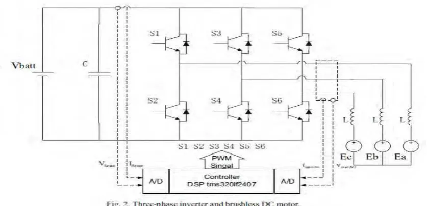
2.6.2 Regenerative braking system for electric bicycle based on DSP Author by
Chih-Chiang Hua, Shih-Jyun Kao
In this research, regenerative braking recovery energy for electrical bicycle has been use to charge the battery. This system does not add any extra converter or ultra-capacitor. While, it been using only DSP(Digital Signal Processor) controller as a control unit. DSP controller far knows as tms320If2407 is a controller used to adjust the switching sequence of the inverter. The propose controlling this inverter so that the braking energy can be returned to charge up the battery. With the help of DSP control unit and regenerative braking energy recovery technologies, the braking energy that produce when motor acts as generator will be converted to electrical energy and return to battery. [5]
9 The kinetic energy that produce at the armature of the motor when motor acts as generator will be converted to electrical energy by using DSP controller will be discuss in this research. When the battery power is send to drive the motor, the power will flow through the armature inductor and store the energy. The stored energy will make the armature current increase. When this happen, the current back EMF also will be increase making it to affect the performance of the battery charging in regenerative braking. To overcome this problem, the charge armature current will released by the discharge circuit mode.
Motor will be in generator mode when the system receives braking signal. The back EMF of the BLDC motor will be used to charge up the battery. However, there is problem using back EMF energy in this condition. The back EMF energy is still being less than battery power even if the motor generate at a higher rate. Moreover the current produce when power switching operation will be distribute to motor armature and will make the power at DC motor side bigger than the battery power. On this condition, the circuit will change mode similar with the boost convertor where the braking energy of DC motor will charge the battery. The changing mode of the inverter is controlled by DSP control unit. Through this regenerative braking storage, the system can improve the traveling range of the bicycles where the losses battery power has been minimize and the and also have improved the performance.
2.6.3 Fuzzy Logic Control in Regenerative Braking System for Electric Vehicle Author by Hao Zhang; Guoqing Xu; Weimin Li; Meilan Zhou.
10 be used as storage energy either in battery or ultra-capacitor. So this research tells that the fuzzy logic control matted can produce more braking energy and increase the overall electrical vehicle efficiency and also the system is more feasible to use. [6]
2.6.4 Research on the lead-acid battery and Ultra-capacitor Energy Storing System of Motor Vehicles Regenerative Braking Author by Chen Qing-zhang; Ma
Wen-bin; Chen Xian-feng;
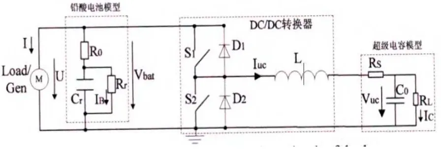
In this research, studied have been made on the lead-acid battery and ultra-capacitor. A two quadrant DC-DC converter have been place between the lead-acid battery and ultra-capacitor. The regenerative braking energy that produce when the motor acts as generator know as kinetic energy will be converted into electrical energy and is charge into an energy storing device so that it can be utilize back to provide extra energy to vehicle. The storing device that used in this system is the lead acid battery and ultra-capacitor. That system used the braking energy to charge the lead-acid battery and ultra-capacitor and the charge will be reuse back together with battery energy provide extra energy to the motor for power up. The regenerative energy can be store straight to lead-acid battery without using capacitor but system is using a capacitor. The purpose of using this ultra-capacitor because it can charge energy fast compare to lead-acid battery slow charges to store the braking energy. so by using this ultra-capacitor the extra energy that can’t be achieve stored In lead-acid battery will be stored in ultra-capacitor. [7]
11 Figure 2.4 show the circuit diagram of the double energy system construct by using lead-acid battery, ultra capacitor and using two-quadrant DC/DC converter. The purpose use DC/DC converter is to control the barking energy so that the ultra-capacitor will be used fully to balance the vehicle load. Other than that, it will also limit the charge rate of battery to ultra-capacitor. The regenerative braking energy will charge the ultra-capacitor first. If the ultra-capacitor is not fully charged, the battery will help to full the charge. If the ultra-capacitor is fully charged, then only the battery will charge. When motoring mode, the energy will be supplied from both ultra-capacitor and battery in as same time together to energies to the motor and give the motor a greater wheel power to motor.
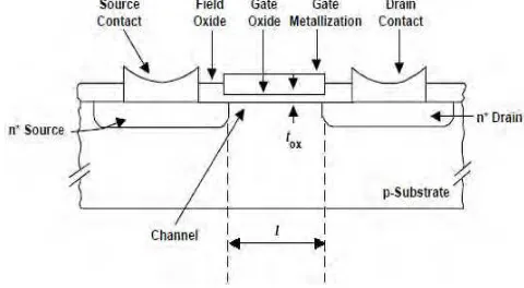
2.7 Power MOSFET
The creation of the power MOSFET was actually created due to limitation of bipolar power junction transistor (BJT) and it’s become one of the popular and advance choices in power electronic application. The bipolar power transistor is one of the devices that use as a current controller. To run the device, it’s requiring amount of one-fifth of collector current at the base to keep the device in ON condition. As it is too fast turn-off, it’s requiring a high reverse current at the base of the device. Figure 2.5 and figure 2.6 below shows the schematic and symbol of the MOSFET.
Figure 2.5: MOSFET symbol Figure 2.6: MOSFET schematic