i Design and Development of Electromagnetic Micro-Generator for Harvesting Energy
from Vibration
LIM SOON YIN
This report is submitted in partial fulfillment of the requirements for the award of Bachelor of Electronic Engineering (Industrial Electronics) With Honours
Faculty of Electronic and Computer Engineering Universiti Teknikal Malaysia Melaka
ii UNIVERSTI TEKNIKAL MALAYSIA MELAKA
FAKULTI KEJURUTERAAN ELEKTRONIK DAN KEJURUTERAAN KOMPUTER
BORANG PENGESAHAN STATUS LAPORAN
PROJEK SARJANA MUDA II
Tajuk Projek : Design and Development of Electromagnetic Micro-generator for Harvesting Energy From Vibration
Sesi Pengajian : 1 5 / 1 6
Saya LIM SOON YIN mengaku membenarkan Laporan Projek Sarjana Muda ini disimpan di Perpustakaan dengan syarat-syarat kegunaan seperti berikut:
1. Laporan adalah hakmilik Universiti Teknikal Malaysia Melaka.
2. Perpustakaan dibenarkan membuat salinan untuk tujuan pengajian sahaja.
3. Perpustakaan dibenarkan membuat salinan laporan ini sebagai bahan pertukaran antara institusi pengajian tinggi.
4. Sila tandakan ( √ ) :
SULIT* *(Mengandungi maklumat yang berdarjah keselamatan atau kepentingan Malaysia seperti yang termaktub di dalam AKTA RAHSIA RASMI 1972)
TERHAD** **(Mengandungi maklumat terhad yang telah ditentukan oleh organisasi/badan di mana penyelidikan dijalankan)
TIDAK TERHAD
Disahkan oleh:
__ ________________________ ___________________________________
(TANDATANGAN PENULIS) (COP DAN TANDATANGAN PENYELIA)
Tarikh: ……….. Tarikh: ………..
iii “I hereby declare that the work in this project is my own except for summaries and quotations which have been duly acknowledge.”
Signature : ...
Author : LIM SOON YIN
iv “I acknowledge that I have read this report and in my opinion this report is sufficient in term of scope and quality for the award of Bachelor of Electronic Engineering (Industrial Electronics) with Honours.”
Signature : ...
Supervisor’s Name : PROF. MADYA DR.KOK SWEE LEONG
vi
ACKNOWLEDGEMENT
Apart from the efforts of me, the success of this project depends largely on the encouragement and guidelines of many others. I would like to take this golden opportunity to express my gratitude to the people who have been instrumental throughout the successful completion of this project.
First and foremost, I would like to offer my sincerest gratitude to my supervisor, Associate Professor Dr. Kok Swee Leong, who has supported me throughout my thesis with his patience and knowledge. Without him, this thesis would not have been completed or written. Encouragement either physically or mentally is given to me to carry on with my final year project till the end. I would also like to thank him for showing me some examples that are related to the topic of my project. All these are vital factors which drives me till the end.
In addition, I am also grateful to friends who have provided me useful opinions and suggestions along the implementation of this project. They are always by my side without failure when they are needed and provide me beneficial advices.
On the other hand, I would like to thank my family members for supporting and encouraging me to complete this project. I would like to offer thanks and deepest gratitude from the bottom of my heart for all the supports, encouragement an inspirations I obtained throughout the duration of this project.
vii
ABSTRACT
viii
ABSTRAK
Berjuta-juta sensor bertaburan di sekeliling tempat kerja akibat daripada hasil penemuan jaringan penderia tanpa wayar yang semakin popular dalam bidang penyelidikan dan pembangunan dan juga penggunaan di industri. Rangkaian penderia sebelum ini adalah dibekalkan dengan sumber kuasa yang berwayar. Walaupun penghantaran tanpa wayar telah menjadi penyelesaian kepada isu ini , namun peranti dalam rangkaian-rangkaian masih memerlukan kuasa elektrik. Penjana elektromagnetik mikro merupakan sistem penuaian tenaga yang menyediakan cara alternatif untuk menghidupkan peranti elektronik selain daripada menggunakan batteri. Sistem ini dapat mengubah tenaga getaran kepada tenaga elektrik. Projek ini membincangkan rekabentuk dan pembangunan penjana elektromagnetik mikro untuk tujuan menuai tenaga daripada sumber getaran. Kedua-dua bahagian mekanikal dan elektronik akan dibincangkan melalui projek ini. Bagi bahagian mekanikal, penjana elektromagnetik yang terdiri daripada asas penjana, gegelung magnet dan struktur julur telah dibina. Sifat frekuensi resonans struktur julur terhadap kepanjangan dan jisim hujung telah dikaji untuk merekabentuk penjana yang beroperasi dalam ringkungan frekuensi 40-50
Hz dengan sumber getaran bermaknitud 0.2 g. Penjana dengan isipadu 13.6 cm3 telah
dibina dengan kepanjangan struktur julur 4.5 cm. Penjana ini mampu menjana voltan
ac sebanyak 461 mVrms dengan sumber getaran 0.2 g. Sementara itu, peranti elecktronik
memerlukan kuasa dc dan sumber output penjana elektromagnetik adalah tidak mencukupi. Oleh itu, litar pengurusan kuasa voltan rendah yang terdiri daripada pendua voltan gelombang penuh dan cas pam tiga peringkat direka. “Shockley diode” NSR0320MW2T dengan penurunan voltan serendah 0.24 V pada aliran 10 mA telah digunakan dalam rekaan agar voltan ac yang rendah dapat direktifikasikan. Litar yang
dihasilkan mampu merektifikasikan voltan ac yang serendah 354 mVrms. Dengan input
461 mVrms, litar tersebut mampu merektifikasikan dan menyimpan cas sebanyak 3.33 V.
ix
TABLE OF CONTENTS
PROJECT TITLE ... i
PROJECT STATUS CONFIRMATION FORM ... ii
STUDENT DECLARATION ... iii
SUPERVISORY DECLARATION ... iv
DEDICATION ... v
ACKNOWLEDGEMENT ... vi
ABSTRACT ... vii
ABSTRAK ... viii
TABLE OF CONTENTS ... ix
LIST OF TABLES ... xiii
LIST OF FIGURES ... xiv
CHAPTER I ... 1
INTRODUCTION ... 1
1.1 Project Overview ... 1
1.2 Motivation ... 2
1.3 Problem Statement ... 2
1.4 Objectives of Project ... 3
1.5 Scope of Works ... 3
1.6 Significant of Project ... 4
1.7 Thesis Structure ... 5
CHAPTER II ... 6
LITERATURE REVIEW... 6
x
2.2 Studies on existing vibration energy harvesting system ... 7
2.2.1 Comparison of different vibration transduction mechanism ... 8
2.2.2 Basic principles of electromagnetic energy harvesting ... 9
2.2.3 Generic mechanical-to-electrical conversion model ... 11
2.2.4 Previous research works on electromagnetic micro-generator ... 12
2.3 Cantilever tuning techniques ... 16
2.3.1 Length ... 17
2.3.2 Mass ... 17
2.4 Studies on ac to dc converter circuits ... 18
2.4.1 Bridge Network ... 18
2.4.2 Voltage doubler ... 19
2.4.3 Voltage tripler and quadrupler... 20
2.4.4 MOSFET cross-coupled rectifier ... 21
2.4.5 Active ac/dc voltage doubler power up by passive ac/dc voltage doubler ... 22
2.4.6 Boost converter in parallel with buck-boost converter... 23
2.4.7 Comparison between rectification components ... 23
2.5 Studies on temporary energy storage device ... 24
2.5.1 Rechargeable Battery... 24
2.5.2 Capacitor and Supercapacitor ... 25
2.5.3 Comparison of energy storage devices ... 26
2.6 Studies on dc to dc converter circuits ... 26
2.6.1 CMOS low voltage charge pump ... 26
2.6.2 Three stage charge pump ... 27
xi
CHAPTER III ... 29
METHODOLOGY ... 29
3.1 Operation block diagram ... 29
3.2 Operation flow chart ... 30
3.3 Design of electromagnetic micro-generator ... 31
3.3.1 Generator base ... 31
3.3.2 Magnetic copper coil ... 32
3.3.3 Cantilever structure ... 33
3.3.4 Neodymium Iron Boron (NdFeB) magnets ... 35
3.3.5 Justification on the choice of material ... 35
3.3.6 Building of electromagnetic generator ... 36
3.4 Experimental setup for generator performance testing ... 37
3.5 Rectifier circuit design ... 38
3.6 DC-DC converter ... 41
3.7 Experimental setup for application testing ... 43
3.8 Conclusion ... 44
CHAPTER IV ... 46
RESULTS AND DISCUSSIONS ... 46
4.1 G-level variation response ... 46
4.2 Factors that affect the resonant frequency of the cantilever ... 47
4.2.1 Length of cantilever variation responses ... 47
4.2.2 Proof masses variation response ... 50
4.3 Charge pump variation response... 52
4.4 Output analysis of electromagnetic micro-generator ... 53
xii
4.6 Discussion ... 55
4.7 Conclusion ... 56
CHAPTER V ... 57
CONCLUSION AND FUTURE WORK ... 57
5.1 Conclusion ... 57
5.2 Future Work ... 58
REFERENCES ... 60
APPENDIX A: MODELLING OF GENERATOR BASE ... xvi
APPENDIX B: MODELLING OF CANTILEVER STRUCTURE ... xvii
xiii
LIST OF TABLES
Table 2.2.1: Comparison of general characteristic of different energy harvesters ... 8
Table 2.2.2: Comparison of outputs of different energy harvesters ... 8
Table 2.4.1: Advantage and disadvantage of different rectification components ... 24
xiv
LIST OF FIGURES
Figure 2.1.1 Most ambient vibration sources investigated are in the region of 0-100 Hz at low level acceleration below 0.2 g result summary plotted by its
acceleration and frequency (Rahman and Kok, 2011) ... 7
Figure 2.2.1: Electromagnetic generator by Zhu and Beeby (2011) ... 10
Figure 2.2.2: A schematic diagram of linear, inertial generator developed by William and Yates (1995) ... 12
Figure 2.3.1: Cantilever structure with mass placed at the tip ... 16
Figure 2.4.1: Full-wave bridge rectifier ... 18
Figure 2.4.2: Input and output waveforms of full-wave bridge rectifier ... 19
Figure 2.4.3: Full-wave voltage doubler ... 20
Figure 2.4.4: Voltage tripler and quadrupler ... 20
Figure 2.4.5: Differential MOS cross-coupled zero-voltage-switching full-wave rectifier developed by Qingyun et. al (2011) ... 21
Figure 2.4.6: Autonomous ac/dc converter with passive and active ac/dc doubler proposed by Hassan et. al (2015) ... 22
Figure 2.4.7: Proposed boost converter in parallel with buck-boost converter proposed by Dwari and Parsa (2010) ... 23
Figure 2.6.1: Proposed four stages charge pump associates with waveforms of pumping nodes by Shantanu et. al (2007) ... 27
Figure 2.6.2: Interface block diagram with dc-dc converter by Hasan et.al (2015) ... 28
Figure 3.1.1: Block diagram indicating the overall experimental setup ... 29
Figure 3.2.1: Flow chart of this project ... 31
Figure 3.3.1: Design of the base of generator ... 32
Figure 3.3.2: Winded magnetic wire coil ... 32
Figure 3.3.3: Cantilever structure of copper and plastic materials at different lengths ... 33
Figure 3.3.4: Different sizes of Neodymium Iron Boron (NdFeB) magnets ... 35
Figure 3.3.5: Assembly of electromagnetic micro-generator... 36
xv
Figure 3.4.2: Setup of electromagnetic micro-generator on electrical shaker ... 38
Figure 3.5.1: Common full-wave bridge rectifier with silicon diodes ... 39
Figure 3.5.2: Rectified DC output from common full-wave bridge rectifier with silicon diodes ... 39
Figure 3.5.3: Full-wave voltage doubler with Shockley diodes ... 40
Figure 3.5.4: Rectified DC output from full-wave voltage doubler with Shockley diodes ... 41
Figure 3.6.1: Full-wave voltage doubler with three stages charge pump ... 42
Figure 3.6.2: Fabricated full-wave voltage doubler with three stages charge pump (front view) ... 42
Figure 3.6.3: Fabricated full-wave voltage doubler with three stages charge pump (back view) ... 43
Figure 3.7.1: Experimental setup for application testing ... 43
Figure 3.7.2: The wirelessly controlled bulb in switched on condition ... 44
Figure 4.1.1: Induced voltage at different g-level for different cantilver length ... 47
Figure 4.2.1: Graph of comparison of induced voltage against frequency for different cantilever length ... 48
Figure 4.2.2: Trend line indication based on frequency versus different cantilever length ... 49
Figure 4.2.3: Graph of induced voltage versus frequency for different weight of proof masses ... 50
Figure 4.2.4: Trend line indication based on frequency versus different weight on cantilever tip ... 51
Figure 4.3.1: Voltage output versus charging time for different stages of charge pump (supercapacitor as energy storage) ... 52
Figure 4.3.2: Voltage output versus charging time for different stages of charge pump (normal electrolytic capacitor as energy storage) ... 52
Figure 4.4.1: Induced AC-RMS from the electromagnetic micro-generator with a vibration level of 0.2 g at its resonance frequency... 53
1
CHAPTER I
INTRODUCTION
1.
In this chapter, the main concept and objectives of the project will be discussed. Besides, the problem statement explains the project significant. The main elements of the project are discussed in the scopes of work. The common structure of this project will also be explained thoroughly.
1.1 Project Overview
A micro-generator is a term used to indicate a device which generates electrical power in micro-Watt scale. Meanwhile, energy harvesting is a term describing the process of producing power obtained from external ambient source for example solar, thermal and vibration energy. The main focus of this project is to harvest energy from vibration source. Ambient vibration which can be transformed into mechanical energy can be found almost everywhere and it can potentially be deployed into wireless sensor networks (WSNs). Therefore, converting vibration energy into electrical energy had become an attractive approach for powering wireless sensors. Vibrations can be found in many environment of interest, the sources including in the buildings, parking lots, air ports, industrial factories and even housing areas. The sources of vibration may be from heavy machinery, home appliances, Heating Ventilation and Air Conditioning (HVAC) vents, movement of people or vehicles or other movements.
2 vibration frequency as they are mostly resonant systems. Therefore, any difference between these two frequencies will result in a drastic decrease in the power produced. This paper presents the development of an electromagnetic micro-generator to harvest energy from vibration by simulating the vibration level with an electrical shaker at approximately 0.2 g at frequencies between 40-50 Hz. The generator is then integrated with the low voltage power management circuit to power up a RF transmitter to switch on a wirelessly controlled bulb.
1.2 Motivation
The power density of batteries is low and its lifespan are limited. The motivation of this project is to produce an alternative power source using vibration energy harvester which has the same functionality yet with capabilities which is beyond batteries.
Wired power source is only limited to the area that is reachable meanwhile batteries must be recharged or replaced and eventually disposed. Therefore, the energy harvesting system is motivated as an alternative for micro-powering. The vibration energy harvester can eventually permeate the environment and integrated seamlessly into sensor networks.
1.3 Problem Statement
Wireless sensor networks (WSNs) are one of the pervasive computing technologies. Meanwhile, energy supply plays a critical factor in this design as it needs reliable operation for extended periods without human intervention. Wired energy infrastructure had been precluded due to its difficulties in reaching inaccessible place. Therefore, vibration energy harvesting had been receiving considerable amount of interest to be used to power up WSNs.
3 rectification, the output voltage will be too low to be implemented in wireless sensor node.
Besides, Rathishchandra and Ian (2012) also described the problems faced by this technique is electromagnetic generator is hard to integrate into micro size for smart sensor application. The structure of conventional electromagnetic micro-generator is hard to be deployed into small electronic devices as it is bigger in size compared to the existing batteries product. Meanwhile William et.al (2001) mentioned that the power output of a small size of vibration-based generator is relatively low due to the small inertial mass. In order to produce sufficient electrical energy, large magnet with stronger magnetic field and high number of turns of wire coils are needed. Therefore, the generator becomes inconvenient to be located at places where human intervention is not allowed.
1.4 Objectives of Project
The objective of this project is to build a structure of electromagnetic micro-generator which operates at a resonance frequency in the range of . Besides, a low voltage power management circuit to transform the low AC voltage generated to a usable level of DC voltage to power up RF transmitter will be designed. Furthermore, this project also evaluates and verifies the performance of the micro-generator constructed in in-lab experiment. Lastly, the micro-generator is integrated with the low voltage power management circuit to power up a RF transmitter to switch on a wirelessly controlled bulb.
1.5 Scope of Works
This part discusses the elements involved in this project. The scope of this project can be identified as following:
4 than 24 cm3 will be build. The output voltage of the generator is expected to be more or equal to 400 mVpeak(rms) at resonant frequency around 40-50 Hz.
The electromagnetic micro-generator designed will work solely depended on electromagnetic theory. The electromagnetic micro-generator build with steel base is work according to the oscillation of a copper cantilever with Neodymium magnets from Bunting Magnetics Europe Ltd work. The cantilever will oscillate around a magnetic coil winded using magnetic wires (AWG 34 SPN) from Magnetic Sensor Systems, Van Nuys.
ii. LT spice software is used to simulate the low voltage power management circuit. A low voltage power management circuit which can produce an output of 3.3 V is simulated as a signal conditioning circuit.
iii. RF transmitter (AFZE-5004) is used to interface with the low voltage power management circuit and micro-generator for switching on a wirelessly controlled light bulb.
iv. The prototype will be tested only through experimental setup by introducing the vibration level with an electrical shaker. The vibration level of the shaker will be set at approximately 0.2 g measured by using a piezo-crystal accelerometer with at a resonance frequency ranges from 40- 50 Hz.
1.6 Significant of Project
This project will be a significant endeavor in promoting green technology. Vibrational kinetic energy can be harvested from the surroundings continuously to power up small electronic devices instead of using chemical batteries which may cause pollutions to the environment.
5 can be left to work on its own without human intervention as long as there is a source of vibration. As such, cost on operational and maintenance will be reduced.
The electromagnetic micro-generator can be made in size that is possible to be deployed in some inaccessible places. By having this advantage, the generator can be integrated with wireless sensor nodes in a large wireless sensor network for monitoring purposes. This also can improve assets utilization as condition is monitored while assets are still in service and earning revenue.
1.7 Thesis Structure
This reports delivers the idea generated, concepts applied, activities done and prototype of the project. It comprises of 5 chapters.
Chapter 1 provides readers with the basic introduction of the project. This chapter includes the introduction, objectives, problem statements, scopes of work, brief methodology and report structure.
Chapter 2 is the literature review on theoretical concepts applied in this project. This chapter includes background study of several existing electromagnetic micro-generator and factors affecting the resonance frequency of the cantilever. In addition, it also includes the background study of the rectifying circuits and dc-dc converter for the purpose of designing the low voltage power management circuit.
Chapter 3 introduces methodology of the project. This chapter contains the flow chart which explains the overall method used along the implementation of this project.
Chapter 4 shows the results for the project outcome. It also includes the discussion of this project. The discussion includes the problems encountered throughout the designing process of the miniature electromagnetic micro-generator.
6
CHAPTER II
LITERATURE REVIEW
2.
This chapter will review on the existing energy harvesting systems invented to obtain idea about the project design, concept and other related information to improve on this project. Besides, low voltage energy harvesting circuits done by various researchers will be reviewed.
2.1 Useful ambient vibration source
There are different vibration sources exhibits at this environment which is useful for energy harvesting. In order to develop an electromagnetic micro-generator that can be deployed in real environment, studies are done on the useful ambient vibration source that can be harvested from the surrounding. The vibration level can be measured as the acceleration of gravity (g).
It is stated that the vibrations available in the surrounding are generally with low level frequencies lower than 500 Hz and at acceleration at approximately 0.1 g according to the studies by Kok, Neil and Nick (2011). The data are collected with an accelerometer and portable data acquisition system (USB measurement module and laptop).
7 Figure 2.1.1 Most ambient vibration sources investigated are in the region of 0-100 Hz at low level acceleration below 0.2 g result summary plotted by its acceleration
and frequency (Rahman and Kok, 2011)
According to the summary shown, it is also noticeable that blender, stand fan, grinding machine and car vibration are sources which vibrate at high acceleration. These vibration sources exhibit high vibration energy to be harvested for further application.
2.2 Studies on existing vibration energy harvesting system
8
2.2.1 Comparison of different vibration transduction mechanism
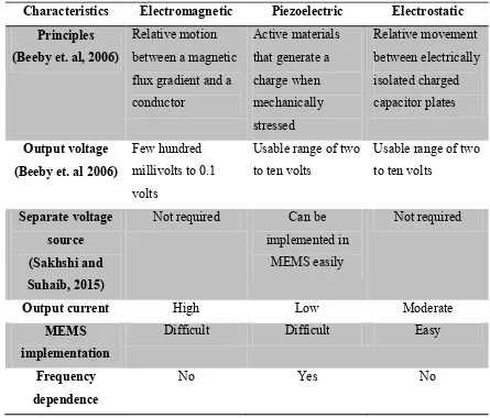
A comparison of general characteristic among the three vibration energy harvesting techniques in relation to different features is done in Table 2.2.1.
Table 2.2.1: Comparison of general characteristic of different energy harvesters
Characteristics Electromagnetic Piezoelectric Electrostatic Principles
(Beeby et. al, 2006)
Relative motion between a magnetic flux gradient and a conductor
Active materials that generate a charge when mechanically stressed Relative movement between electrically isolated charged capacitor plates Output voltage (Beeby et. al 2006)
Few hundred millivolts to 0.1 volts
Usable range of two to ten volts
Usable range of two to ten volts
Separate voltage source (Sakhshi and Suhaib, 2015)
Not required Can be
implemented in MEMS easily
Not required
Output current High Low Moderate
MEMS implementation
Difficult Difficult Easy
Frequency dependence
No Yes No
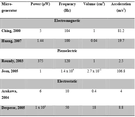
9 Table 2.2.2: Comparison of outputs of different energy harvesters
Micro-generator
Power (μW) Frequency (Hz)
Volume (cm3) Acceleration (m/s2)
Electromagnetic
Ching, 2000 5 104 1 81.2
Huang, 2007 1.44 100 0.04 19.7
Piezoelectric
Roundy, 2003 375 120 1 2.5
Jeon, 2005 1 1.4 x 10⁴ 2.7 x 10⁻⁵ 106.8
Electrostatic
Arakawa, 2004
6 10 0.4 4
Despesse, 2005 1 x 10³ 50 18 8.8
By comparing the electromagnetic generator of Huang, 2007 and piezoelectric generator of Jeon, 2005 from Table 2.2.2, it is noticeable that the size of electromagnetic generators is relatively large in order to generate approximately equivalent power output. Besides, electromagnetic generator of Ching, 2000 is also relatively big in size compared to Arakawa, 2004 in order to generate approximately equivalent power output.