1
CHAPTER 1
INTRODUCTION
1.1 Project Background
This project is all about the “Portable Power Supply from Wave Energy”. The term of “portable” meaning that the product of this project is easily to moveable anywhere because of the size is small. This portable power supply is able to produce electricity where it can be use for military purposes or for the outdoor activities such as picnic and camping.
There are two types of energy source in the world which non-renewable energy and renewable energy. Once a non-renewable energy source is used, it cannot be replace but renewable energy source is one that can be replacing and it is good for our environments. The term of “renewable” referred to its energy because it does not finish even though it is use regularly. This energy has a few advantages than non-renewable energy such as the energy is free because its form natural resources, it’s clean to the environment and cheaper. There are many types of renewable energy available on earth but the ocean wave is one which growing up recently according to the research and development to harnessing their energy.
This project intended to generate electricity by using wave energy with the aid of solenoid and permanent magnet. The literature review is cover about the permanent magnet, copper wire, ocean wave and previous study on ocean wave.
2
turns are used in this testing. Some analysis and discussion need to be done after preliminary testing completed.
The full-scale model has been developing as a real model of a wave energy device. This model was tested in a real situation. So that, harvesting the ocean wave energy and convert it to the electricity power.
1.2 Problem Statement
This project is constructing based on a few problem statement. Firstly, is about the non-renewable energy. Nowadays, power plants use sources such as diesel, coal and gas. Once these are burned to generate electricity, their energy is lost forever. It is thought that the current resources for oil and gas under the North Sea will last about another 20 years and the world resources will last for about 70 years. Even though the world has relatively larger reserve for coal but it is expected that the coal can be lasting only for the next century [9]. For that reason, developing an alternative energy is must for future demand.
Besides that, the oil price has increased up to $100.00 per barrel and all countries anxious with this situation [10]. Therefore, to solve this oil prices crisis, the ocean wave is used as the alternative energy to generate electricity.
Next, the problem associated with fossil fuels uses are that the extraction of fossil fuel causes local environment problem including damage to land surface, noise, dust, acid rain and pollution [11]. In order to reduce this effect, the wave energy is harnessing to obtain a green energy for electricity.
An additional, the past research and product has a bulky size and apply on the open sea only. It is fixed design and unremoveable product. Therefore, to make the product more comfortable and convenient, this project has an advantages because of it size is small and allocate at the seaside.
3
cost to build it. Compare with the new one, it is cheaper because the material used is not much and more simply than the old one.
1.3 Objective
The objectives of this project are:
1. To generate induced current with the aid of magnet and solenoid
2. To analyze the effect of magnet, solenoid and relative movement of magnet to the electrical characteristics
3. To develop a hardware for harnessing the wave energy.
1.4 Scope of Project
In order to achieve the project objectives, the following scopes will be covered: 1. Studies the literature reviews about the magnet, copper wire, ocean wave
and previous study on ocean wave.
2. Identifies the circuits and components and procurement of components and materials.
3. Conduct a preliminary testing by using various shapes of permanent magnet and number of wire turns to understand and verify the system principle. 4. Construct the full scale model by using wave energy to generate electricity.
4
CHAPTER 2
LITERATURE REVIEW
2.1 Ocean Wave Energy
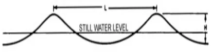
Ocean has a sinusoidal waveform where the highest peak is called crest and lowest part is called troughs. The difference in height between peaks and troughs is known as height, H and the distance between successive peak (or troughs) of wave is known as a wavelength, λ [1]. The wave period T is the time interval between passage of successive crests at a stationary points.The shape of ocean wave is shown in Figure 2.1 below:
Figure 2.1: Shape of Ocean Wave
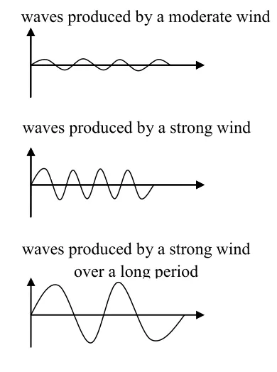
Waves are generated when wind passing over the sea. There is an energy transfer from the wind to the most of wave when the waves propagate slower than the wind speed. Waves growth happened when there are difference in both air pressure between the upwind and the lee side of a wave crest.
5
There are three type of wind wave which is capillary waves or ripples, sea and swells. Ripples appear on smooth water when the wind blowing but it will die quickly if there is no wind. The irregular motions under sustained winds as called sea and they much longer than the ripples even after the wind is died. Swells are created when seas propagate away from their area of origin.
2.1.1 Ocean Wave Characteristic
The wave power is determined by wave speed, wavelength and water density. Usually, when the wave is larger we can say that the wave is more powerful than the smaller one.
As mention in previous section, we can suppose that the peaks and troughs of ocean wave move across the surface with the velocity, υ and time in seconds is taken for successive peaks (or troughs) is known as the period, T. When the waves travel at velocity υ, it will travel a distance that it’s equal to its wavelength λ in a time equal to the wave period T. So, the velocity υ is equal to the wavelength λ divided by the period of T. The mathematically equation can be express in Equation 2.1 below:
T
λ
υ= (2.1)
In deep water waves, if the water is greater than the half of its wavelength, the velocity of ocean wave can be express in Equation 2.2:
The properties of the waves is increases by water depth when the water become shallower and when it reach shallow water, their properties are completely is taken by the water depth but for the intermediate depths the properties of the waves is influenced by both water depth d and water period T. When the waves approach the shore, the seabed starts to have an effect on their speed and this can be show if the water depth d is less than a quarter of the wavelength. The current velocity in this stage is shown in Equation 2.3 below:
2
gT
υ = π (2.2)
gd
6
The characteristic of an idealized wave is shown in Figure 2.2 below:
Figure 2.2: Characteristic of Idealized Wave
Wave energy is depends on wind speed, time duration of the wind blowing, the distance of open water that the wind has blown over and water depth. Wave power could be determined by wave height, wavelength and water density [2]. This mathematically could be described as in Equation 2.4 [3].
7
where; ρ : density of seawater (kg/m3)
g : acceleration due to gravity (m/s2) H : wave height (m)
2.1.2 Ocean Wave Energy Technologies
In order to capture energy from sea waves, variety of technologies has been used to harnessing the wave energy to convert into useful electrical energy. However, each is in too early a stage of development to predict which technology or mix of technologies would be most prevalent in future commercialization [3].
Wave energy converter is devices that can be convert the wave energy to electrical energy which it is central, stable structure and have some active part which moves relative to it under the force of the waves. There are many different configuration of wave energy converter and a number of ways of classifying them have been proposed. One schematic representation of the various types wave energy converter is shown in Figure 2.3 below [1].
8
Wave energy converters can be classified in terms of their location [1]: a) Fixed to the seabed, generally in shallow water.
b) Floating offshore in deep water or c) Tethered in intermediate depths
According to the paper “Numerical Modeling of the Electric Linear Generator Based on the Sea Wave Energy”, permanent magnet linear generator can be used as to producing electrical energy based on clean resources, such as sea waves energy. These generators have special features in comparisonwith other types of electric generators. They take the advantage of renewable energy resources such as it’s do not pollute the environment, have to be water-proofed, and can be built in a range of various powers without having geometricaldimensions limitations [4].
The operating principle of this project is simple where there is an armature with permanent magnet at the central of their designed. The armature will anchored to the sea floor, and the floater moves the permanent magnet relative to the fixed armature coils to induce voltage. In Figure 2.4 below, it show the sketch of the entire system. Part number 1 show the translating armature, part number 2 is a fixed armature with coils, part number 3 is a shaft, part number 4 is a fixing pillar, part number 5 is a buoys/floater, part number 6 is a rope and part number 7 is a spring.
9
Otherwise, the wave energy converter can divided into three categories based on their geometry and orientation such as terminator, attenuators and point absorbers.
2.1.2.1 Terminator
Terminator devices extend perpendicular to the direction of wave travel and capture orreflect the power of the wave. These devices are typically installed onshore or nearshore. However, floating versions have been designed for offshore applications. The oscillating water column (OWC) is an example form of terminator in which water enters through a subsurface opening into a chamber with air trapped above it. The wave action causes the captured water column to move up and down like a piston to force the air though an opening connected to a turbine. A full-scale, 500-kW, prototype OWC designed and built by Energetech in year 2006 shown in Figure 2.5 and it is undergoing testing offshore at Port Kembla in Australia, and a further project is under development forRhode Island [3].
Figure 2.5: Oscillating Water Column [3]
10
2.1.2.2 Attenuators
Attenuators are long multisegment floating structures oriented parallel to the direction of the wave travel. The differing heights of waves along the length of the device causes flexing where the segments connect, and this flexing is connected to hydraulic pumps or other converters [3]. The example of attenuators is Pelamis by Ocean Power Delivery, Ltd.
The Pelamis is a semi-submerged machine, articulated structure composed of cylindrical sections linked by hinged joints. The wave-induced motion of these joints is resisted by hydraulic rams, which pump high-pressure oil through hydraulic motors via smoothing accumulators. The Pelamis contains three Power Conversion Modules, each rated at 250kW (sea tested for 1000 hours in 2004).
The first stage, scheduled to be completed in 2006, consists of three Pelamis machines with a combined rating of 2.25 MW to be sited about 5 km off the coast of northern Portugal. An expansion to more than 20-MW capacity is being considered.
A Pelamis powered 22.5-MW wave energy facility is also planned for Scotland, with the first phase targeted for 2006 [3]. Figure 2.6 below show the Pelamis Wave Energy Converter.
11
2.1.2.3 Points Absorbed
Point absorbers have a small horizontal dimension compared with the vertical dimension and utilize the rise and fall of the wave height at a single point for wave energy converter. One of example of this points absorbed is Aqua Buoy.
The Aqua Buoy being developed by the AquaEnergy Group, Ltd. In year 2005 this point absorber is the third generation of two Swedish designs that utilize the wave energy to pressurize a fluid that is then used to drive a turbine generator. The vertical movement of the buoy drives a broad, neutrally buoyant disk acting as a water piston contained in a long tube beneath the buoy. The water piston motion in turn elongates and relaxes a hose containing seawater, and the change in hose volume acts as a pump to pressurize the seawater. The Aqua Buoy design has been tested using a full-scale prototype, and a 1-MW pilot offshore demonstration power plant is being developed offshore at Makah Bay, Washington. The Makah Bay demonstration will include four units rated at 250 kW placed 5.9 km offshore in water approximately 46 m deep [3]. The Aqua Buoy Point Absorber Wave Energy Converter is show in Figure 2.7 below.
12
2.2 Magnet
Magnet is a material or object that produces a magnetic field. The magnet has at least two poles where it is North Pole and South Pole. Magnet that has same pole (N-N or S-S) will repelled to each other but when they has difference pole (N-S or S-N) they will attracted to each other.
The magnetic fields of magnet are invisible but we can see them in when scatter the iron filing around the magnet. The lines that created by iron filing are called magnetic field which they leave the North Pole and enter the South Pole of magnet. Inside the magnet, the field line travels from South Pole to North Pole. Magnetic field will strong when the field lines are close together and become weak if the field lines are far away from one another.
There are three type of magnetism such as ferromagnetism, diamagnetism and paramagnetism. Ferromagnetism is a material that when we placed it near a magnet, it will be attracted toward the region of greater magnetic field. Example for this material is iron, cobalt, nickel, gadolinium, dysprosium and alloys. Diamagnetism is a material that when we placed it near a magnet, it will be repelled from the region of grater magnetic field such as copper, gold, silver and lead. Paramagnetism is a material that when we placed it near a magnet, it will be attracted to the region of greater magnetic field. The difference paramagnetic and ferromagnetic material is that the attraction of paramagnetic material is weak than ferromagnetic material.
The magnet is employing concept of electromagnetic induction such as Faraday’s Law, Lenz’s Law and Fleming’s Right-Hand Rule. The Faraday’s Law is a basic law of electromagnetism where this law states “The induced electromotive force or EMF in any closed circuit is equal to the time rate of change of the magnetic flux through the circuit”. Equation 2.6 below shows the equation of Faraday’s Law [12]:
B
Φ = magnetic flux through the circuit (in webers)
13
The direction of the induced electromotive forces or EMF and current is given by Lenz’s Law where the law states “An induced current is always in such direction as to oppose the motion or change causing it”. In the other words this law state that the induced EMF and the change in flux have opposite signs of Faraday’s Law. The Fleming’s Right-Hand Rule shows the direction induced current flow when a conductor moves in magnetic fields. The right hand is held with the thumb, first finger and second finger mutually perpendicular to each other. The direction of induced current is shown in Figure 2.8 below [13]:
Figure 2.8: Direction of Induced Current
The tens facts of magnet are show in below [8]:
1) North Poles point north, South Pole point south 2) Like pole repel, unlike pole attract
3) Magnetic forces attract only magnetic materials 4) Magnetic forces acts at a distance
5) While magnetized, temporary magnet acts like permanent magnet
6) A coil of wire with an electric current flowing through it becomes a magnet 7) Putting iron inside a current carrying coil increases the strength of the
electromagnet
8) A changing magnetic field induces an electric current in a conductor
14
10) A current carrying wire in a perpendicular magnetic field experiences a force in a direction perpendicular to both the wire and the field.
There are three main types of magnet such as permanent magnet, temporary magnet and electromagnet. Permanent magnets are use for this project and there are four classes of permanent magnets such as Neodymium Iron Boron (NdFeB), Samarium Cobalt (SmCo), Alnico and Ceramic or Ferrite.
2.2.1 Characteristic of Permanent Magnet
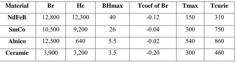
The permanent magnet has a characteristic just like another magnet. The special characteristic of four classes of permanent magnet is shown in Table 2.1 below [8]:
Table 2.1: Special Characteristics of Permanent Magnet
Material Br Hc BHmax Tcoef of Br Tmax Tcurie
NdFeB 12,800 12,300 40 -0.12 150 310
SmCo 10,500 9,200 26 -0.04 300 750
Alnico 12,500 640 5.5 -0.02 540 860
Ceramic 3,900 3,200 3.5 -0.20 300 460
Br - measure of its residual magnetic flux density in Gauss, which is the maximum flux the magnet, is able to produce.
Hc - measure of the coercive magnetic field strength in Oersted, or the point at which the magnet become demagnetized by an external field.
BHmax - term of overall energy density. The higher the number, the more powerful
the magnet.
Tcoef of Br - temperature coefficient of Br in terms of % per degree Centigrade.
Tmax - maximum temperature the magnet should be operated at. After the
15
Tcurie - Curie temperature at which the magnet will become demagnetized. After
the temperature drop this value, it will not behave as it did before it reached that temperature.
2.2.2 Selection of Permanent Magnet
Before start the project, selection of magnet is most important that needs to be considered. This is including:
i. Magnetic properties ii. Corrosion resistance iii. Material cost and
iv. Maximum operating temperature
A good permanent magnet should produce a high magnetic field with a low mass and should be stable against the influences which would demagnetize it. The desirable properties of such magnet are typically stated in terms of remanence and coercive of the magnet material [6].
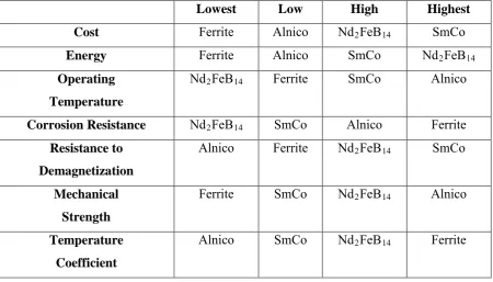
Alnico, Nd2Fe14B and SmCo magnet are classified as the rare earth permanent
16
Table 2.2: Comparison between Four Types of Permanent Magnet Material
Lowest Low High Highest
Corrosion Resistance Nd2FeB14 SmCo Alnico Ferrite
Resistance to
A rare earth permanent magnet, Nd2Fe14B is chosen as a component for this project
based on number of considerations especially in terms of producing high energy product. The physical, mechanical and magnetic properties of the magnet such as thermal conductivity, specific heat, electrical resistivity and magnetic flux density which are affected by temperature are investigated. Nd2Fe14B magnet is selected due to its high
energy at its maximum operating temperature [6].
2.2.3 The Care of Permanent Magnet