UNIVERSITI TEKNIKAL MALAYSIA MELAKA
DESIGN AND ANALYZE OF FLYWHEEL PLATE FOR FLYWHEEL HYBRID MODULE
This report submitted in accordance with requirement of the Universiti Teknikal Malaysia Melaka (UTeM) for the Bachelor Degree of Engineering Technology
(Automotive Technology) (Hons.)
by
MUHAMMAD AFIQ BIN JALALUDIN
B071110099
921217-08-5663
FACULTY OF ENGINEERING TECHNOLOGY 2015
ABSTRACT
Fuel efficiency is a thermal efficiency of energy convert or transfer. There are a lot of technologies that have been invented to improve the fuel efficiency for the vehicle. For example, hybrid car use electric motor to assist the internal combustion engine. The principle working of hybrid vehicle is depends on its drive train structure. Regenerative braking is a one of the
working principle of hybrid electric vehicle that stored the energy during deceleration. However, there is another technology that has same working principle to regenerative braking that is
kinetic energy recovery system. This system use flywheel to stores the energy because it has high energy density with the increasing of rotational speed. So, this project is conduct to design and analyze the flywheel plate for the flywheel hybrid module. Flywheel hybrid module consists of flywheel plate, clutch system, transmission system and shaft with housing. Flywheel hybrid module will be implemented in the front rim of motorcycle. There will need to consider amount of space available for the flywheel plate. The material of flywheel plate also important thing that affect the density which will relies the capability of energy storage by the flywheel. In this project, design of the flywheel plate has been done until the concept sketching. The future work will be continues on the next semester.
ABSTRAK
Kecekapan bahan
api adalah kecekapan haba memeluk tenaga atau pemindahan. Terdapat banyak teknologi yang direka untuk meningkatkan kecekapan bahan api untuk kenderaan. Sebagai
contoh, kereta hibrid menggunakan motor elektrik untuk membantu enjin pembakaran dalaman. Pengerjaan prinsip kenderaan hibrid adalah bergantung kepada struktur memandu kereta api itu. Brek regeneratif adalah salah satu prinsip kerja kenderaan elektrik hibrid yang disimpan tenaga semasa nyahpecutan. Walau bagaimanapun, terdapat satu lagi teknologi yang mempunyai prinsip
kerja sama untuk brek regeneratif yang kinetik sistem pemulihan tenaga. Ini penggunaan sistem r oda tenaga ke kedai-kedai tenaga kerana ia mempunyai kepadatan tenaga yang
tinggi dengan peningkatan kelajuan putaran. Oleh itu, projek ini adalah menjalankan untuk mereka bentuk dan menganalisis plat roda tenaga bagi modul roda tenaga hibrid. Modul roda tenaga hibrid terdiri daripada plat roda tenaga, sistem klac, sistem
penghantaran dan aci dengan perumahan. Roda tenaga modul hibrid akan
dilaksanakan dalam rim hadapan motosikal. Ada perlu mengambil kira jumlah ruang yang ada untuk plat roda tenaga. Bahan plat roda tenaga juga perkara penting yang memberi kesan kepada ketumpatan yang akan bergantung keupayaan penyimpanan tenaga dengan roda tenaga. Dalam projek ini, reka bentuk plat roda
tenaga yang telah dilakukan sehingga lakaran konsep. Kerja-kerja masa depan akan terus pada semester yang akan datang.
ACKNOWLEDGEMENT
I would like to express my special appreciation and thanks to my project supervisor
MUHAMMAD ZAIDAN B. ABDUL MANAF, you have been a tremendous mentor for me. I would like to thank you for encouraging my project and for allowing me to grow as a
technologist student. Your advice on project as well as on my experience has been priceless. I would also like to thank my project members for serving as my project members even at
hardship. I also want to thank you for your brilliant comments and suggestions, thanks to you. I would especially like to thank to all technician and teaching lecturer in the Faculty of
Engineering Technology at University Technical Malaysia Melaka that involved in guiding my in this project. All of you have been there to support me during completing this project.
A special thanks to my family. Words cannot express how grateful me to my parents for all of the sacrifices that you’ve made on my behalf. Your prayer for me was what sustained me thus far. I would also like to thank all of my friends who supporting me in this project, and incanted me to strive towards my goal.
TABLE OF CONTENT
Mechanical hybrid system ... 14
Mechanical hybrid based on flywheel energy storage ... 15
Advantages of flywheel ... 17
Chapter 3 ... 19
RESEARCH METHODOLOGY ... 19
Introduction ... 19
Benchmarking ... 23
Product development specification ... 25
Design concept ... 26
Morphological chart ... 27
Concept generation ... 31
Concept evaluation ... 32
CHAPTER 4 ... 35
RESULT ... 35
DETAIL DESIGN ... 35
MESHING COMPONENT ... 36
ANALYSIS ... 38
ChAPTER 5 ... 50
DISCUSSION ... 50
CHAPTER 6 ... 51
CONCLUSION ... 51
References ... 52
CHAPTER 1
INTRODUCTION
Background
Flywheel is a rotating mechanical device that is used to store rotational energy. Flywheels have a significant moment of inertia and thus resist changes in rotational speed. The amount of energy stored in a flywheel is proportional to the square of its rotational speed. Energy is transferred to a flywheel by applying torque to it, thereby increasing its rotational speed, and hence its stored energy. Conversely, a flywheel releases stored energy by applying torque to a mechanical load, thereby decreasing its rotational speed. Flywheel is used in many ways of applications such as in automotive, wind turbines, motor sports, grid energy storage, laboratories and rail vehicle.
In automotive system today, there are a lots of technology used to optimize the fuel efficiency. While many automakers have turned to turbocharged diesel and hybrid-electric propulsion in recent years to improve fuel economy and cut emissions, several companies, including Porsche, are trying out a different track. Taking a page out of Formula One racing, they are testing electromechanical kinetic energy recovery systems (KERS), which were
developed to enable racecars to store braking energy in spinning flywheels for later use during acceleration. Now, Volvo Car Corp. has joined their ranks.
In this project, it will be more on mechanical-hybrid system that called a flywheel hybrid module. Flywheel hybrid module will consist of flywheel plate, transmission system, clutch system and shaft with housing.
Problem statement
Front rim of motorcycle has limited space because the front rim’s width is always smaller than rear rim’s width. The conventional front rim of motorcycle only has only 1.6 inch width. So, this will become a problem to make an improvement on front rim for motorcycle power. The front rim also has been installed with brake system and speedometer. So, there is need a consideration of space for brake system and speedometer. The components in the flywheel hybrid module are also very complex because there is a limited of space. The flywheel diameter size should be less than 17 inch since the rim only has a diameter of 17 inch.
The flywheel width size also should be less than 1.6 inch. The difficult part is the clutch system for engage and dis-engage the flywheel to absorb and release the energy. There will be a major modification on the motorcycle in way of engage and dis-engage of flywheel which is
more on clutch system. This modification on front rim will increase the weight of the front rim and make it become more complex. The motorcycle will use new front rim that locate all the components. The rim will become the housing that will locate all the components.
Objective
There are two main objectives that need to be achieved in order to complete this project.
• To design the flywheel plate for flywheel hybrid module. • To analyze the flywheel plate for flywheel hybrid module.
Scope of project
To designs and analyze the flywheel plate for flywheel hybrid module. The result will consider the stress level on the flywheel plate and the design that can sustain the max rotation of the flywheel. There will be three type of flywheel design that is ring, solid disk and ring with circular end. For the power analysis, it will use math equation for flywheel power and calculate the max power conserve in flywheel. There will be a change in moment for a different shape of flywheel. Moment of inertia can be calculated manually or by using Catia.
CHAPTER 2
LITERATURE REVIEW
Motorcycle
Motorcycle has two type of internal combustion engine (ICE) there is two strokes engine and four strokes engine. Two stroke engines can complete one power cycle within two cycles, while four strokes engine can complete one power cycle within four cycles. Two strokes engine has more power and torque compare to four strokes engine. Even two strokes engine has less engine capacity than four strokes engine, but two strokes engine has more power than four strokes engine. Unfortunately, the fuel consumption for four strokes engine is more efficient than two strokes engine. That’s why today two strokes engine is not relevant and reliable.
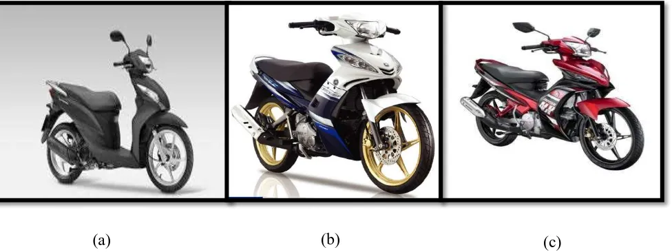
This study will be more on four strokes engine motorcycle power system. The power system for motorcycle is depends on what type of transmission does the motorcycle use. There are two types of transmission system which is manual transmission with hand clutch or auto clutch and automatic transmission. Figure 2.1 shows a various type of motorcycle transmission. There are some advantages and disadvantages between them. Transmission system is important to deliver and transmit the rotational energy and torque from crankshaft to the gearing system in order to enhance speed or torque to the drive line. This study will found on how we can implement new power system on motorcycle’s rim in order to enhance the fuel efficiency of motorcycle.
Motorcycle rim is important thing that makes the motorcycle to moving through the rotational of rims with the tire attached to it. As usual we can see that all the motorcycle that moving on the road is using two separated rims. We can see that the rear rim will be driven by the engine. The front rim is less complex than rear rim. Rear rim consist of sprocket and brake while front rim consist of speedometer cable and brake. Motorcycle rim have it own size and dimension. It depends on the engine capacity of motorcycle. The bigger the engine capacity, the bigger rim is needs to stabilize the power. Figure 2.2 shows a spoke rims that are available in market. While the figure 2.3 is an example of solid rims that available in market.
Figure 2.1: (a) Scooter with automatic transmission. (b) Motorcycle with auto clutch transmissions system. (c) Motorcycle with manual clutch transmission system. (Source: Hong Leong Yamaha)
(a) (b) (c)
Figure 2.2: Spoke rim Figure 2.3: Solid rim
(Source:
Previous studies
Hybrid system is a power system that uses two different types of system that is internal combustion system and electric motor system. Both systems can be combined and configured to improve fuel economy, increase power, additional auxiliary power device and power tools. Hybrid system also has equip the advance technology to improve the efficiency such as regenerative braking, electric motor drive support and automatic start shut off. Figure 2.4 show the components in hybrid vehicle.
For the regenerative braking, during braking or deceleration, the motor will acts as a generator to converts the rotational of drive shaft into an electrical energy and store it into battery. While for the electric motor drive or assist, the motor will assist the internal
combustion engine during accelerating, passing, or hill climbing. This will allow the smaller and more efficient engine to be used. Sometimes, the internal combustion engine and electric motor does not assisting each other. In some hybrid system design, the electric motor alone provides power for low-speed driving conditions where internal combustion engines are least efficient.
All hybrid vehicles are not created to be equal but they are depending on degrees of hybridization of the vehicle created and the different drive train. Hybrid vehicle can be determines it degrees of hybridization by considering five technological characteristics that separate the conventional vehicle from the electric vehicle. The five technological
characteristics of hybrid vehicle are idle-off capability, regenerative braking capacity, power assist or engine downsizing (mild hybrid), electric-only drive (full hybrid) and extended battery-electric range (plug-in hybrid).
There are many different of drive train structures for hybrid that is parallel hybrid (mild hybrid), series hybrid (extended range hybrid) and power-split or series-parallel hybrid. Parallel-hybrid system consists of both internal combustion engines with electric motor coupled. Both are coupled in parallel axis so they will be has same speed and summation of torque. Parallel hybrid use smaller battery pack and rely mainly on regenerative braking to
recharge the battery back. Figure 2.5 shows the various type of drive train structure in hybrid vehicle.
(b) Parallel hybrid
(c) Series-parallel hybrid
Figure 2.5: Various type of drive train structure for hybrid vehicle. (Source:http://www.ucsusa.org)
Mechanical hybrid system
Hybrid system is consists of two type that is hybrid electric system and hybrid mechanical system. Hybrid electric system is used in hybrid electric vehicle where it fulfills the requirement as a vehicle that emits the emission rate of 2% (M. Ehsani, 1997). Hybrid electric vehicle used more than one combination power sources to move the vehicle that is mechanical and electric.
In hybrid mechanical system vehicle, mechanical energy is obtained from internal
combustion engine and electric energy is obtained from energy that stored in the battery to move the vehicle. This system also requires electrical energy delivery system to convert electrical energy to mechanical energy. Electrical hybrid can be classified into series system and parallel system.
Mechanical hybrid system consists of internal combustion engine (ICE) and flywheel energy storage. Components in mechanical hybrid are different from electrical hybrid components where the flywheel is use as a secondary power sources by storing a kinetic energy and use it to vehicle’s wheel. Mechanical hybrid system used flywheel as the energy storage because it has minimum weight and size. Flywheel also is made from material that can achieve maximum speed and maximum shear stress allowable.
Mechanical hybrid based on flywheel energy storage
There are two basic components in kinetic energy recovering system, which are:- 1. A method of storing and recovering energy from drive train.
2. Energy storage medium.
Electrical hybrid system used chemical battery as energy storage medium and motor or generator as energy transfer and control medium. In conjunction with that, mechanical hybrid used rotating matter or flywheel as an energy storage and transfer device to the drive train. Kinetic energy release system (KERS) stores the rotational energy during braking and release it during acceleration.The flow of energy in a mechanical hybrid system from the initial kinetic energy of the vehicle goes through a series of rotating shafts and gears and end up as kinetic energy in the rotating flywheel.
This kind of storage is clearly needs to convert the energy from another form into another form.For example, electric KERS system must recover the kinetic energy of the vehicle, then convert this electricity using an electric motor, thereby changing the electrical energy from one voltage to another and eventually transform electrical energy into chemical potential energy in the battery (Douglas, 2008).
To release the rotational energy to the wheel, every process in the system need to reverse back.Any changes of energy will bring the loss of energy occurs and the overall efficiency is low compared to mechanical storage. The transfer of kinetic energy from vehicle to the flywheel can be seen as a changed of momentum. Kinetic energy is gathers from the vehicle and supplies it to the flywheel.
In this situation, flywheel is gathering rotating energy during braking which is flywheel rotating speed is increase. At the initial of braking, vehicle has a high speed rotating energy while the flywheel has a low speed rotating energy, there will be certain gear ration during this situation. At the end of braking, vehicle speed will be reduces while the flywheel will rotates at high-speed, so the speed ratio is change. The results show that the ratio of energy transfer between the vehicle’s speed and the speed of the flywheel undergoing continual change during the process of energy transfer (Douglas, 2008).
To cope with the continuous changes in the ratio between the flywheel and the wheels, continuously variable transmission (CVT) is used. The energy transfer is due to the 'push' or 'pull' on the CVT ratio. That is, if the ratio of the speed of the flywheel (RPM) / wheel (RPM) is a known value, then by giving a higher ratio will tend to increase the speed of the flywheel, and thus slow down the rotation of the wheel, causing the transfer of kinetic energy occurs. The same thing would happen if that system is reversed. So by giving the ratio of low speed flywheel will decrease and the wheel speed increases, so energy transfer occurred which accelerated the speed of the vehicle.
Advantages of flywheel
Mechanical hybrid consists of mechanism that used kinetic energy to store the energy. However, recent studies more focused on the flywheel with technological breakthroughs or Kinetic Energy Recovery System (KERS) by vehicle manufacturers such as Volvo. The KERS system is also used by the Williams Formula 1 racing car.
Flywheel
Flywheel is defined as the disk-shaped flywheel spins to store kinetic energy. More speed rotating flywheel more kinetic energy can be stored. Rotating flywheel with a connecting rod known as the shaft. The shaft will transfer energy either into or out of the flywheel. Use of the flywheel as a second power source has many advantages compared with the use of an electric motor that uses a battery to move the electric motor. One of the advantages of the flywheel is to improve the space in a hybrid electric. The idea of using alternative power sources that use less energy required components such as flywheel. (Lagunoff, 2008).
In the case of a flywheel hybrid, flywheel will acts as motors, generators and batteries. In this case, energy is stored as mechanical energy in form of rotation of flywheel (Mehmet, 2008). During deceleration (regenerative braking), flywheel will acts as generator that store kinetic energy in form of flywheel rotation. While during acceleration, flywheel will acts as motor that use stored energy in it. By using a single component than two components in electric hybrid, the mass of the space issue can be resolved. Figure 2.6 shows two types of flywheel shape.
(a) Flat type
(b) Rim type
(Source: http://www.ricardo.com) Figure 2.6: Two types of flywheel shape. (a) Flat
Performance
Flywheel stored kinetic energy relies on the mass moment of inertia and rotational speed. There are three factors that affect the flywheel performance that is material strength,
geometry (cross-section) and rotational speed. Material strength is important in other to run the flywheel at high rotational speed. So, this will allow the flywheel to store more energy. Rotational speed of flywheel will control the energy store. The higher speed of flywheel, the more kinetic energy can be stored. But, during high speed rotation, there will be more excessive load exert on the flywheel and bearing. The geometry of flywheel will affect the kinetic energy storage capability of the flywheel.
Any optimization effort of flywheel cross-section may contribute substantial
improvements in kinetic energy storage capability thus reducing both overall shaft/bearing loads and material failure occurrences. Flywheel efficiency includes the amount of specific kinetic energy (energy per unit mass) and mechanical losses (Shahare, 2013). Amount of energy stored is a function of the moment of inertia and angular velocity, as shown in equation (2.5.2.1).
Energy stored
,
�
=
12��
2(2.5.2.1)
�
is the moment inertia and � is the angular velocity. The moment of inertia is determined by it shape, mass and radius of flywheel as shown in equation (2.5.2.2).Moment of inertia,
�
=
���
2(2.5.2.2)
Where,I is moment of inertia
k is the inertia constant
CHAPTER 3
RESEARCH METHODOLOGY
Introduction
This section will explain about how this product is develops. It covers the constraint in this project, flow chart of project, collecting data procedure and analysis of data. Before designing the flywheel plate that will attach on front rim of motorcycle, all the data obtain needs to follow the method of engineering design process. Method in engineering design process is start from benchmarking activity until refining the design.
Flow chart of PSM 1& 2
Overall Methodology
Benchmarking Process
Product Development Specification
Morphological chart
Concept generation
Concept selection (concept scoring)
PSM 1
Conceptual sketching
Conceptual design
Start
PSM 2
Configuration Design
Parametric Design
Detailed Design
Analysis
End
GHANTT CHART
A. PROJECT PLANNING
List down the main activity for the project proposal. State the time frame needed for each activity.
Benchmarking
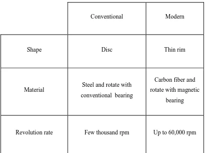
Benchmarking process was made by comparing the advantages and disadvantages of flywheel design with different shape. There are two different design shapes that have in the market. First is the rim type flywheel, second is the flat type flywheel. Table 3.3.1 shows that comparison between flywheel disc and flywheel rim.
Conventional Modern
Shape Disc Thin rim
Material Steel and rotate with conventional bearing
Carbon fiber and rotate with magnetic
bearing
Revolution rate Few thousand rpm Up to 60,000 rpm
(Anthony, 2011) Table 3.3.1: Comparison of different flywheel shape
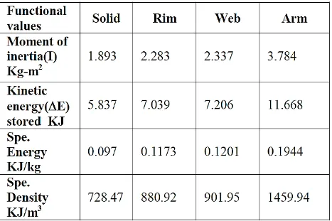
The flywheel has its own specific energy that is kinetic energy storage capability. This kinetic energy capability is depending on the flywheel shape. Table 3.3.2 shows the comparison of various flywheel shapes with it functional values. The all type of flywheel has the same mass and diameter. The mass is 60kg and diameter is 500mm.
Table 3.3.2: Comparison of various flywheel shapes with functional values.
(Choudary, 2013)