UNIVERSITI TEKNIKAL MALAYSIA MELAKA
DESIGN AND ANALYZE THE TRANSMISSION SYSTEM FOR
FLYWHEEL HYBRID MODULE
This report submitted in accordance with requirement of the Universiti Teknikal Malaysia Melaka (UTeM) for the Bachelor Degree of Engineering Technology
(Automotive Technology) (Hons.)
by
MUHD SHAMIL IQRAM BIN RAZALI B071110299
921225-14-5364
DECLARATION
I hereby, declared this report entitled “Design and Analyze the Transmission System for Flywheel Hybrid Module” is the results of my own research except as
cited in references.
Signature : ……….
Author’s Name : ………
APPROVAL
This report is submitted to the Faculty of Engineering Technology of UTeM as a partial fulfillment of the requirements for the degree of Bachelor of Engineering Technology (Automotive Technology) (Hons.). The member of the supervisory is as follow:
ABSTRAK
Projek ini bertajuk "Rekabentuk dan Analisis Sistem Penghantaran Mekanikal Roda Tenaga Modul Hibrid". Dalam kertas ini, pembangunan mekanisme asas dan reka bentuk konsep sistem penghantaran Modul Hibrid Mekanikal roda tenaga dipaparkan. Sistem gear planet atau sistem gear kisar digunakan dalam projek ini. Penggearan planet adalah sistem gear yang terdiri daripada satu atau lebih gear planet, berputar mengelilingi gear matahari yang terletak di tengah-tengah set gear. Biasanya, gear planet yang bercantum pada pembawa planet berputar berpaksikan gear matahari. Sistem penggearan kisar juga berfungsi dengan menggunakan gear cincin luar yang juga dikenali sebagai anulus. Gear planet bersentuhan dengan anulus. Keseluruhan kedudukan gear biasanya selari. Tambahan pula, pembawa gear planet, gear matahari dan kedudukan anulus umumnya sepaksi.
ABSTRACT
This project is entitled “Design and Analyze of the Transmission System for Mechanical Flywheel Hybrid Module”. In this paper, the development on basic mechanism and conceptual design of the transmission system of the Mechanical Flywheel Hybrid Module is shown. The planetary gear set or epicyclical gearing system is used. Planetary gearing is a gear system consisting of one or more planet gears, rotating about a sun gear which is located at the centre of the gearing set. Normally, the planet gears are attached on a planet carrier which itself revolve relative to the sun gear. Epicyclic gearing systems also function and use an outer ring gear acknowledged by the name of annulus. Planet gear meshes with the annulus. The axes of all of those gears are usually parallel. Furthermore, planet carrier, the sun and annulus axes are generally coaxial.
DEDICATION
ACKNOWLEDGEMENT
TABLE OF CONTENT
CHAPTER 3: METHODOLOGY 21
5.1 Conclusion 56
5.2 Future Work 57
LIST OF TABLE
3.1 Benchmark for 3 car makers 23
3.2 The new product components 23
3.3 Concept Generation 28
3.4 Concept Generation Chart 29
3.5 Concept Scoring 30
3.6 Mild Steel Mechanical Properties 32
3.7 Simple Planetary Gear Operation 33
3.8 Gear Efficiency Comparison Table 35
3.9 Gear Specification 36
3.10 Model Gear Ratio 36
3.11 Component Material Selection 38
4.1 Angular Speed of each gear for Low Speed Analysis 47
4.2 Low Speed Charging Comparison 48
4.3 Angular Speed of each gear for Medium Speed Analysis 50
4.4 Medium Speed Charging Comparison 51
4.5 Angular Speed of each gear for High Speed Analysis 53
4.6 High Speed Charging Comparison 54
LIST OF FIGURES
2.1a Toyota Prius 5
2.1b Honda Insight 5
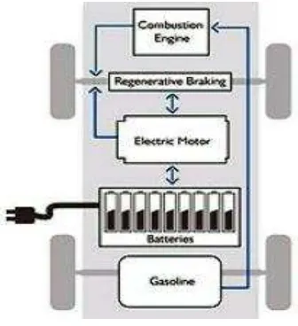
2.2 Diagram of a Plug-in Hybrid Electric Vehicle 5
2.3 Illustration of a Series Hybrid Drive Train 7
2.4 Illustration of a Parallel Hybrid Drive Train 8
2.5 How Regenerative Brake System Works 10
2.6 Mechanical KERS: The Flybrid® 9013 hybrid systems as fitted to the
Jaguar XF demonstrator 13
2.7 Sectional Views of a Final Rotor 14
2.8 Side view of a Manual Transmission Engine 17
2.9 Example of Automatic Transmission System 19
2.10 Example of Belt-type CVT 20
3.1 Flowchart PSM 1 21
3.2 Flowchart PSM 2 22
3.3 Simple Planetary Gear System 33
3.4 Example of Spur Gear 35
3.5 Spur Gear Terminology 35
3.6 CATIA V5R19 Design Interface 37
3.7 Planetary Gear Designer V1.03 Interface 38
3.9 Planet Gear Model 39
3.10 Ring Gear Model 40
3.11 Planet Carrier Model 40
4.1 Model Assembly 41
4.2 Drawn pitch diameter for all gears 42
4.3 Point located on pitch diameter of each gear 43
4.4 The planetary gears all in mesh 43
4.5 Sun Gear and Planet Gear in mesh 43
4.6 Planet Gear and Ring Gear in mesh 44
4.7 Set the time parameter with speed input data 45
CHAPTER 1
INTRODUCTION
1.1Background Study
Wheeled vehicle that transports passengers and carries its own engine is called an automobile. Nowadays automobiles comprise with modern technology such as sensors and actuator. Undoubtedly, it was not invented by a single inventor in a blink of time. In 1890s, with the horseless carriers were being invented, it was clearly indicated that the automotive industry has begun. Since then, the consumption of natural gas and fossil fuel had increased greatly and it is expected to be reduced as time goes by. Many alternatives and technologies had been invented and manufactured such as catalytic converters, electronic fuel injectors and aerodynamic body design in order to cut and reduce the engine fuel consumption. Besides, it is also to preserve the global towards a greener and cleaner world.
On the other hand, vehicle which uses two or more power sources to make the car propel is called as a hybrid car. The two power sources are an internal combustion engine (ICE) and an electric motor. This technology is slowly gaining popularity among the car buyers as they see the benefits that owning a hybrid will contribute to a greener world. With hybrid technology, the car’s carbon footprint will be reduced as the energy usage is efficient. The mechanical hybrid system recycles kinetic energy which would be otherwise wasted when a vehicle brakes. The entirely mechanical arrangement provides a commercially possible and cost effective substitute to battery-based electric hybrid systems.
recovers kinetic energy, stores it in the revolving flywheel and subsequently returns the energy to the vehicle driveline. Flywheel hybrid module basic gears are; a flywheel plate, a clutch system, shaft and housing, and a transmission system. Focusing on transmission system, it is a gathering of parts including the speed-changing gears which the power is transmitted from regenerative braking to the flywheel and then to the drive train.
1.2Project Title
Design and Analyze the Transmission System for Flywheel Hybrid Module.
1.3Problem Statement
The biggest issue of indecision is the compact space of motorcycle. The issue arises when the flywheel hybrid module needs to be assembled on the motorcycle system. The flywheel hybrid module needs to be placed in the most suitable parts so that the module can perform at its best performance with low space needed. The motorcycle engine is already packed with the power and electrical system. Besides, the front side consists of the front brake and the front suspension system. Similarly, the rear side lays the rear brake and rear suspension system with the rear wheel attached to the engine system by chains.
1.4Project Objective
1) To design the transmission system for Flywheel Hybrid Module. 2) To analyze the transmission system for Flywheel Hybrid Module.
1.5Project Scope
The transmission system project scopes are restricted to some method and equipment that have been provided:
Model the transmission system for flywheel hybrid module by using CATIA software.
Simulate the model generated by using CATIA software.
Analyze the transmission system developed by using CATIA software.
1.6Project Significance
CHAPTER 2
LITERATURE REVIEW
2.1 Hybrid Vehicle
A hybrid vehicle is a vehicle that has more than one major source of propulsion power. When the expression hybrid vehicle is used, it frequently refers to a Hybrid Electric Vehicle (HEV). Most hybrid cars nowadays have two major power sources which are conventional internal combustion engine (ICE) and electric motors. These two power sources can operate the vehicle by either one alone or in parallel. The existence of the electric power train is proposed to attain enhanced fuel economy as compared to a conservative vehicle engine. As the engine of the hybrid vehicle is comparably smaller than usual internal conventional engine, it produces less emission.
(a)
(b)
Figure 2.1: (a) Toyota Prius (b) Honda Insight (Sources: (a) Toyota, 2013 (b) Honda Malaysia, 2013)
The hybrids maintain the batteries charged by generating electric power via the regenerative braking system. The electric motor turns into a generator and the magnetic drag retard the vehicle down when the driver applies the brakes. In addition, when the regenerative braking is not adequate, the typical hydraulic braking system will assist the braking mechanism in order to stop the vehicle. In general, regenerative brakes capture energy and turn it into electricity to charge the battery that provides power to an electric motor [2]. The power sources found in a HEV can be combined in numerous ways. However, the most common drive train configurations are the series and parallel HEV.
2.1.1 Series Hybrid
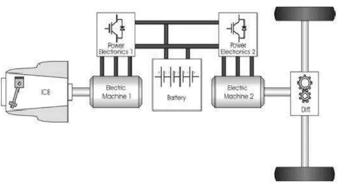
Figure 2.3: Illustration of a series hybrid drive train.
The advantage of series hybrid is that the internal combustion engine can be turned off when the vehicle is cruising in a zero-emission mode. Furthermore, another merit of the series hybrid is that the internal combustion engine and the electric machine can be mounted separately. This involves a possibility to distribute the weight of the vehicle drive system and in buses an opportunity to use low floor (Hemmingsson, 1999, Van Mierla et al, 1998).
2.1.2 Parallel Hybrid
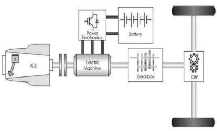
current insist for power can be met. Nevertheless, as the engine is linked straight to the transmission, it cannot always be operated in its most efficient region.
Figure 2.4: Illustration of a parallel hybrid drive train.
2.2 Regenerative Braking
Regenerative braking relates to a method in which a part of the kinetic force of the vehicle is stored by a small period storage space system. Energy generally scattered in the brakes is commanded by a power transmission system to the energy storage space during deceleration. That energy is detained until called for once again by the vehicle, whereby it is changed back into kinetic force and used to step up the vehicle. The amount of the part accessible for energy storage alters according to the storage type, drive train effectiveness, and drive cycle and inertia weight (Clegg, 1996).
Figure 2.5: How regenerative brake system works. [6].
To be successful, a regenerative braking system should ideally have the following properties [7]:
1) Efficient energy conversion
2) An energy store with a high capacity per unit weight and volume
3) A high power rating so large amounts of energy can flow in a short space of time
4) Not require over complicated control system to link it with the vehicle transmission
5) Smooth delivery of power from the regenerative system
6) Absorb and store braking energy in direct proportion to braking, with the least delay and loss over a wide range of road speeds and wheel torques.
schedule. This relative saving is reduced as the weight of the vehicle reduces. A 1000 kg vehicle can achieve theoretical savings of 15% [9, 10].
The main advantages of regenerative braking systems can be summarized [11] as: 1) Improved fuel economy – dependant on duty cycle, power train design,
control strategy and the efficiency of the individual components.
2) Emissions reduction – engine emissions reduced by engine decoupling, reducing total engine revolutions and total time of engine operation (engine on – off strategy).
3) Improved performance.
4) Reduction in engine wear – engine on/off strategy.
5) Reduced in brake wear reducing cost of replacement brake linings cost of labour to install them and vehicle downtime.
6) Smaller accessories – hybrid power train offers potential for eliminating (electric starter) or cost due to the hybrid hardware additions.
7) The operating range is comparable with non conventional vehicles – a problem not yet overcome by electric vehicles.
The possible disadvantages of regenerative braking system can be summarized [11] as:
1) Added weight/bulk – extra components can increase weight, increasing fuel consumption, offset by smaller engine operating at its best efficiency.
2) Complexity – depends on control necessary for operation of regenerative braking system.
3) Cost – of components, engineering, manufacturing and installation. Mass production would bring costs down to a more reasonable level.
4) Noise – depends on the system.
5) Safety – Primary concern with any energy storage unit of high energy density. There must be very little chance of dangerous failure during normal vehicle operation. Passengers must be protected from risks that may be caused by the failure of the hybrid system.
6) Size and packaging constrains – most important for cars.
![Figure 2.5: How regenerative brake system works. [6].](https://thumb-ap.123doks.com/thumbv2/123dok/495486.55150/23.595.220.403.67.281/figure-regenerative-brake-works.webp)
