iii
SCALED CONTROL OF DC MOTORS
NG CHO LIANG
A report submitted in partial fulfillment of the requirements for the degree of Mechatronics Engineering
Faculty of Electrical Engineering
UNIVERSITI TEKNIKAL MALAYSIA MELAKA
ii
“I hereby declare that I have read through this report entitle “Scaled Controled of DC Motors” and found that it has comply the partial fulfillment for awarding the degree of Bachelor of Mechatronics Engineering”
Signature :………. Name : Dr. Ahmad Zaki bin Haji Shukor
iv
I declare that this report entitle “Scaled Controled of DC Motors” is the result of my own research except as cited in the references. The report has not been accepted for any degree and is not concurrently submitted in candidature of any other degree.
Signature :………. Name : Ng Cho Liang
v
vi
ACKNOWLEDGEMENT
vii
ABSTRACT
viii
ABSTRAK
ix
TABLE OF CONTENTS
CHAPTER TITLE PAGE
ACKNOWLEDGEMENT iv
ABSTRACT v
ABSTRAK vi
TABLE OF CONTENTS vii
LIST OF TABLES ix
LIST OF FIGURES x
LIST OF ABBREVIATION xii
LIST OF APPENDICES xiii
1 INTRODUCTION
1.1Motivation 1
1.2 Problem Statement 3
1.3 Objective 3
1.4 Scope 4
2 LITERATURE REVIEW
2.1 Background Study 5
2.2 Theories and basic principles of the DC motor 5
2.3 Types of Sensors 6
2.4 Types of Actuator 7
2.5 Reviews of previous related works 9
2.6 Summary and discussion of review 16
3 METHODOLOGY
3.1 Introduction 17
x
3.3 Block Diagram 18
3.4 Calibrating the current sensor 19
3.5 Project Process 23
3.5.1 Relation of torque parameter 23
3.5.2 Motion Sensing 26
3.5.3 Control Parameter Relationship 29
3.5.4 Time delay parameter 31
4 RESULTS AND DISCUSSION
4.1 Introduction 33
4.2 Calibration results for current sensor 33
4.3 Project Results 35
4.3.1 Relation of Torque Parameter 35
4.3.2 Motion Sensing Result 41
4.3.3 Control Parameter Relationship 45
4.3.4 Time delay parameter 50
5 CONCLUSION
5.1 Introduction 52
5.2 Conclusion and Recommendation 52
5.3 Limitation of Project 53
xi
LIST OF TABLES
Table Title Page
2.1 Speed command and load torque 12
2.2 Comparison between controllers used 17
3.1 Time and current table 22
3.2 Force Sensitive Resistor Value for both DC motors 26
3.3 Reading of Encoder from Arduino Serial 28
3.4 Reading of Rotation by Protractor 29
3.5 Overall Results of the Calculation 29
3.6 Time delay for small and large motor 33
4.1 Current and time data 34
4.2 Force Sensitive Resistor Value 39
4.3 The encoder reading and current reading for both DC motors
39
4.4 Comparison between Theory and Measurement 41
4.5 Reading of Encoder from Arduino Serial 42
4.6 Reading of Rotation by Protractor 42
4.7 Overall Results of the Calculation 43
xii
LIST OF FIGURES
Figure Title Page
1.1 Robot Assisted Microsurgery (RAMS) arm 2
1.2 Pneumatic Filler Liquid (PNEUMAFLOW) 3
1.3 Illustration of scaling using a small motor to a bigger motor 3 1.4 Illustration of scaling using a small motor to a bigger motor 3
2.1 ACS-712 Breakout 7
2.2 Force Sensitive Resistor 7
2.3 SPG30E-150K 8
2.4 IG42E-49K 8
2.5 Motor driver MD10C 9
2.6 Motor driver L298N 9
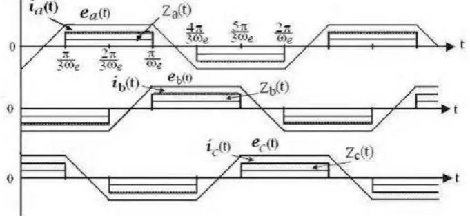
2.7 Waveforms of the EMFs, phase currents and commutating signal for brushless DC motor
10
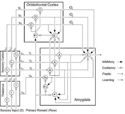
2.8 The sectional structure of the brain, which amygdala shown 11 2.9 Graphical presentation of the computational model of brain
emotional learning
11
2.10 The control structure of the brushless DC motor using BELBIC 12 2.11 Simulation using a conventional PID controller 12
2.12 Simulation of control speed 13
2.13 Multi motor synchronization control system 13
2.14 Fuzzy control with variable scale factor 14
2.15 Adjustment of phase at 33.33Hz 14
2.16 Adjustment of phase 25Hz 14
2.17 Adjustment process of scale factor 15
3.1 Overall flow chart process 18
3.2 Overall system block diagram 19
xiii
3.4 Electric circuit for current sensing 21
3.5 Current versus Time graph 22
3.6 Coding for current sensing 23
3.7 Apparatus set up for two DC motors 24
3.8 Motor link rotates and going touch the force sensor pad 25
3.9 Motor link touched the force sensor pad 25
3.10 Connection of motor driver and encoder 27
3.11 Measuring the angle of the motor link 28
3.12 PV vs time for PID controller 30
3.13 Set up of apparatus with stopwatch 32
4.1 Difference (%) over time (s) graph 35
xiv
LIST OF ABBREVIATIONS
cpm - Cubic feet per minute
s - Seconds in Time
Nm - Newton metre
º - Degree
V - Voltage or Voltage unit
I - Current
A - Ampere unit
RPM - Revolution per minute
α - Angular acceleration
- Power
- Torque
- Angular velocity - Constant
Hz - Hertz
J - Inertia
N - Force
xv
LIST OF APPENDICES
Appendix Title Page
A Gantt Chart for Final Year Project 56
1
CHAPTER 1
INTRODUCTION
1.1 Motivation
DC motors are widely used nowadays no matter in a small or big industry. The usage of DC motor advantage over AC motor is the starting torque. This advantage is important for the processor to save the delay time occurred when measuring the speed. DC motor steady state speed can be achieved in just less than 5 seconds while AC motor tends to use longer than 5 seconds. DC motor is a very useful application in robotics and industrial. For examples in robotics, as shown in Figure 1.1 below. The arm uses for microsurgery in the surgery for complicated surgery. Doctor just needs to move the robot assisted microsurgery (RAMS) and the other end of the micro forceps will apply the small and precise force [1].
2
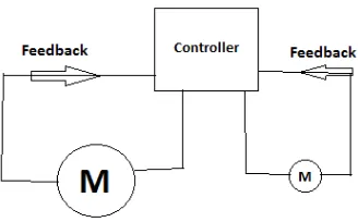
In a pneumatic system, the DC motor used for scaling from small to big motor as shown in Figure 1.2 below. The pneumatic system with 40 head rotary fillers can produce speed up to 400 cpm. The motor can turn from the PLC Allen Bradley controller to the 40 head rotary filler using the provided motor.
Figure 1.2: Pneumatic Filler Liquid (PNEUMAFLOW) [2]
DC motor with higher torque can amplify the torque with a DC motor with a smaller torque as a reference. This shows that the performance of the whole system will improve tremendously and hence given me, an aspiring idea to do this project. Examples of application can be used in this project will be electric cars, robotics parts and pneumatic cylinder in car manufacturing industry. The diagram below Figure 1.3 and Figure 1.4 shows the simple illustration of the project:-
3
1.2 Problem Statement
Due to the lack of performance when running two DC motors together synchronously, the value of the encoder in the motor varies a lot from the actual value. This cause a lot of problems to the user and the system. The system might breakdown or the whole operation will suspended. The problem arises is the deviation of values between the two motors when running together in which, causes the desired setpoint cannot be achieved. Secondly, the deviation to the error percentage of both the DC motor when being rotated and the delay time for the primary motor to the secondary motor response time which causes the motor to operate improperly. The force amplication of the small motor to the large motor need to be known in order to get the exact value after the small motor being rotated. The value of the force decrement from the large motor to the small motor also needs to be found out in order to get the correct decrement of force in the system. However, the tuning of the control parameter from the Proportional Intergral Derivative controller (PID) can reduce the deviation of angle and time delay in the motors.
1.3 Objectives
The objectives for this final year project are:-
1. To implement motion and force amplification for small DC motor to large DC motor which can replicate the movement of each other at different torque and scaling.
2. To implement motion and force decrement for large DC motor to small DC motor which can replicate the movement of each other at different torque and scaling.
4
1.4 Scope
5
CHAPTER 2
LITERATURE REVIEW
2.1 Background Study
Main characteristics of the DC motor depending on the motor current, magnetic field, voltage, torque, load and power. Each of the motors differs by the most important features that is torque and power. In AC motor characteristics, the starting torque will be more than 5s and this will cause time consuming. The steady state for the motor must be as short as possible in order to make the starting torque increase [6].
In DC motors, the speed (RPM) can be easily controlled and change in the desired speed that wanted while in AC motor, the speed hardly manageable due to the changing of the waveform from positive to negative or negative to positive. Normally in the industry, AC motors are being applied because they need a very fast start up speed which can increase the profit of the industry [6].
2.2 Theories and basic principles of the DC motor
6
2.3 Types of Sensors
Current sensor
Figure 2.1: ACS-712 Breakout
The current can sense up to 5Amp with model of xx05b version. The low noise analog signal path makes it easier to get the current data. Device bandwidth is the filter pin. 1.5% output error at 25 ºC. Output voltage proportional to AC or DC currents. Extremely stable output offset voltage which makes the graph stable [7].
Force Sensitive Resistor
Figure 2.2: Force Sensitive Resistor
The maximum mass can be withstood by this force sensitive resistor is 100kg and
7
2.4 Types of Actuator
Smaller torque motor
Figure 2.3: SPG30E-150K
Input voltage is DC12V. Output Power for this motor is 1.1 Watt. The rated speed is 26RPM. The rated current will be 410mA while the rated torque is 0.588Nm [8].
Large torque DC motor
Figure 2.4: IG42E-49K [9]
8
Motor driver
Figure 2.5: Motor driver MD10C
The motor driver which can support up to 25V of voltage in the DC motor. The current that can be input inside the motor driver can up to maximum 13A and 30A peak, which can only hold for 10 seconds. The motor driver provides a bi-directional way of turning. [15]
Figure 2.6: Motor driver L298N
9
2.5 Reviews of previous related works
DC Motor and Control Technique
Application of the DC motors can be controlled by many types of controller. One of it was using an emotional intelligent controller. Based on the article by Daryabeigi in [1], he concluded that the speed of the DC motor can be controlled using an emotional intelligent controller. The controller uses a brain emotional learning based intelligent controller. This intelligent controller inspired by the limbic system of human or animal brain especially in the amygdala. This intelligent controller had a design which looks simple and high auto learning feature. By using Matlab, the results of the simulation show that steady state and fast transient speed responses to a wide range of 20 to 300 rpm. The controller had been compared with a conventional PID controller [1].
Figure 2.7: Waveforms of the EMFs, phase currents and commutating signal for brushless DC motor [1]
10
Based on above Figure 2.7, the equation 2.1 formed and proven that three phase brushless DC motor equivalent to DC brush motor with equal back EMF and equal armature current which proportional to the torque of the system. Therefore, all this parameter can be reduced to a simple scalar control. [1]
Figure 2.8: The sectional structure of the brain, which amygdala shown [1]