ELEN 3441 Fundamentals of Power Engineering Spring 2008
BAB IV MOTOR DC
DASAR TEKNIK TENAGA
LISTRIK
FAKULTAS TEKNIK
INDUSTRI dan MESIN
Uniiversitas
ELEN 3441 Fundamentals of Power Engineering Spring 2008
Electric Motors
Alternating Current (AC) Motors
Direct Current (DC) Motors
Synchronous Induction
Three-Phase Single-Phase
Self Excited Separately
Excited
ELEN 3441 Fundamentals of Power Engineering Spring 2008
dcmotor 4
DC Generator and Load
Prime-mover
(Turbine)
DC Generator
L
oa
d
E
ais Generated voltage
V
Lis Load voltage
ELEN 3441 Fundamentals of Power Engineering Spring 2008
dcmotor 5
and Mechanical Load
DC Motor
V
Tis Applied voltage
T
devis the Torque developed by DC Motor
T
loadis the opposing load torque
I
aV
T+
-ELEN 3441 Fundamentals of Power Engineering Spring 2008
Generator/Motor DC
si
ELEN 3441 Fundamentals of Power Engineering Spring 2008
DC motors
ELEN 3441 Fundamentals of Power Engineering Spring 2008
dcmotor 10
ELEN 3441 Fundamentals of Power Engineering Spring 2008
The simplest DC machine
segments
ELEN 3441 Fundamentals of Power Engineering Spring 2008
ELEN 3441 Fundamentals of Power Engineering Spring 2008
ELEN 3441 Fundamentals of Power Engineering Spring 2008
ELEN 3441 Fundamentals of Power Engineering Spring 2008
ELEN 3441 Fundamentals of Power Engineering Spring 2008
Power Transmission
Tw = Tw
ELEN 3441 Fundamentals of Power Engineering Spring 2008
DC power systems are not very common in the contemporary engineering
practice. However, DC motors still have many practical applications, such
automobile, aircraft, and portable electronics, in speed control
applications…
An advantage of DC motors is that it is easy to control their speed in a
wide diapason.
DC generators are quite rare.
Most DC machines are similar to AC machines: i.e. they have AC voltages
and current within them. DC machines have DC outputs just because they
have a mechanism converting AC voltages to DC voltages at their
ELEN 3441 Fundamentals of Power Engineering Spring 2008
Electric Motor
el
ELEN 3441 Fundamentals of Power Engineering Spring 2008
ELECTROMAGNETISM
FIGURE 8–6 A magnetic field surrounds a current-carrying conductor.
ELEN 3441 Fundamentals of Power Engineering Spring 2008
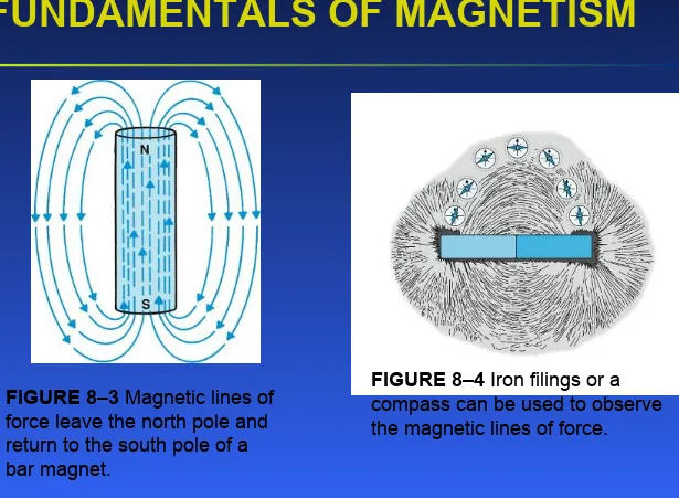
FUNDAMENTALS OF MAGNETISM
FIGURE 8–3 Magnetic lines of force leave the north pole and return to the south pole of a bar magnet.
FIGURE 8–4 Iron filings or a
ELEN 3441 Fundamentals of Power Engineering Spring 2008
ELEN 3441 Fundamentals of Power Engineering Spring 2008
ELEN 3441 Fundamentals of Power Engineering Spring 2008
ELEN 3441 Fundamentals of Power Engineering Spring 2008
ELEN 3441 Fundamentals of Power Engineering Spring 2008
ELEN 3441 Fundamentals of Power Engineering Spring 2008
FUNDAMENTALS OF MAGNETISM
ELEN 3441 Fundamentals of Power Engineering Spring 2008
dcmotor 34
FORE FINGER = MAGNETIC FIELD
900
900
900
MIDDLE FINGER= CURRENT
THU MB
= M OTI
ON
FORCE = B I
Al
ELEN 3441 Fundamentals of Power Engineering Spring 2008
dcmotor 35
FORE FINGER = MAGNETIC FIELD
900 900
900
MIDDLE FINGER = INDUCED VOLTAGE
TH UM
B = M O
TION
VOLTAGE = B
l
uELEN 3441 Fundamentals of Power Engineering Spring 2008
Carrying Conductor
h
e
ELEN 3441 Fundamentals of Power Engineering Spring 2008
depends on the magnitude of the current which it
carries. The force is a maximum when the current
flows perpendicular to the field (as shown in
ELEN 3441 Fundamentals of Power Engineering Spring 2008
the conductor, the external
magnetic field and the force the
conductor experiences
I
F
ELEN 3441 Fundamentals of Power Engineering Spring 2008
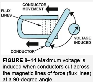
VOLTAGE STRENGTH
FIGURE 8–13 No voltage is induced if the conductor is
moved in the same direction as the magnetic lines of force (flux lines).
ELEN 3441 Fundamentals of Power Engineering Spring 2008
A
B C
D
A B
C D
A B
C D
A B C
ELEN 3441 Fundamentals of Power Engineering Spring 2008
How a DC Motor Works
Brushes
B
L
I
ELEN 3441 Fundamentals of Power Engineering Spring 2008
a magnetic field
N
L
R
S
I
F
F
Rotation
Commutator
(rotates with
coil)
ELEN 3441 Fundamentals of Power Engineering Spring 2008
Vertical position of the loop:
N
S
ELEN 3441 Fundamentals of Power Engineering Spring 2008
Parts of the Motor
r
ELEN 3441 Fundamentals of Power Engineering Spring 2008
ELEN 3441 Fundamentals of Power Engineering Spring 2008
•
The armature is an
electromagnet made by coiling
thin wire around two or more
poles of a metal core.
•
The armature has an axle, and
the commutator is attached to
the axle.
•
When you run electricity into
this electromagnet, it creates a
magnetic field in the armature
that attracts and repels the
magnets in the stator. So the
armature spins through 180
degrees.
•
To keep it spinning, you have
to change the poles of the
ELEN 3441 Fundamentals of Power Engineering Spring 2008
Brushless DC Motor
http://mot-sps.com/motor/tutorial/blac.html
Identify:
•
Permanent Magnets
•
Rotor
•
Brushes
•
Commentator
•
Armature
ELEN 3441 Fundamentals of Power Engineering Spring 2008
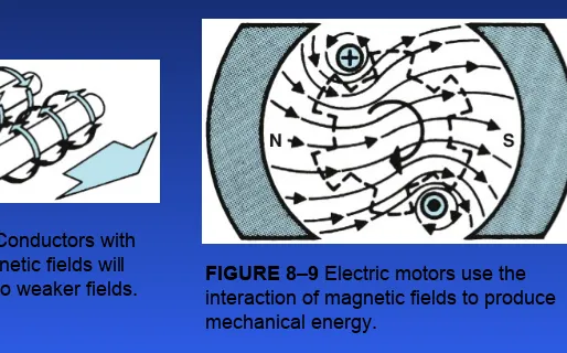
ELECTROMAGNETISM
FIGURE 8–8 Conductors with opposing magnetic fields will
ELEN 3441 Fundamentals of Power Engineering Spring 2008
DC
motor basics
N
S
N S
stator rotor
permanent magnets
commutator
attached to shaft
V +
ELEN 3441 Fundamentals of Power Engineering Spring 2008
DC motor basics
N
S
N S
stator rotor
permanent magnets
N S N S
V +
- V
+
-ELEN 3441 Fundamentals of Power Engineering Spring 2008
DC motor basics
N
S
N S
stator rotor
permanent magnets
N S N S N N S S
V +
- V
+
-V
+
-ELEN 3441 Fundamentals of Power Engineering Spring 2008
Brush DC Motors
Identify:
•
Stator
•
Rotor
•
Brushes
•
Commentator
•
Permanent Magnets
•
Armature
•
Field
http://mot-sps.com/motor/tutorial/blac.html
Electrical Engineering Terms:
Armature: The power-producing component of an alternator, generator, dynamo or motor. The armature can be on either the rotor or the stator.
ELEN 3441 Fundamentals of Power Engineering Spring 2008
ELEN 3441 Fundamentals of Power Engineering Spring 2008
Pulse Width Modulation
(PWM)
ELEN 3441 Fundamentals of Power Engineering Spring 2008
ELEN 3441 Fundamentals of Power Engineering Spring 2008
•
Commutator is simply a pair of plates
attached to the axle. These plates
provide the two connections for the coil
of the electromagnet.
•
Commutator and brushes work together
to let current flow to the electromagnet,
and also to flip the direction that the
ELEN 3441 Fundamentals of Power Engineering Spring 2008
The simplest DC rotating machine consists of a single loop of wire rotating about a fixed axis. The magnetic field is supplied by the North and South poles of the magnet.
Rotor is the rotating part;
ELEN 3441 Fundamentals of Power Engineering Spring 2008
The simplest DC machine
We notice that the rotor lies in a slot curved in a ferromagnetic stator core, which, together with the rotor core, provides a constant-width air gap between the rotor and stator.
The reluctance of air is much larger than the reluctance of core. Therefore, the magnetic flux must take the shortest path through the air gap.
As a consequence, the magnetic flux is perpendicular to the rotor surface everywhere under the pole faces.
ELEN 3441 Fundamentals of Power Engineering Spring 2008
ELEN 3441 Fundamentals of Power Engineering Spring 2008
( Motor atau Generator
1. Kumparan Medan Magnet , menghasilkan
medan magnet
2. Kumparan Jangkar , untuk menginduksi GGL
pada konduktor-konduktor yang terletak pada
alur jangkar
3. Celah udara, untuk memungkinkan
ELEN 3441 Fundamentals of Power Engineering Spring 2008
information
• Model and serial number
– Enable the manufacture to identify the
motor and useful for warranty and replacement
• Type, Horsepower, RPM, and duty
ratios all indicate the capabilities of the motor.
– Horsepower
• 1HP = 33,000lbs lifted one foot in
minute.
• Calculated HP = lbs. lifted x Distance in
feet x time in seconds ÷ 550
• W(LBS) X D(FT) X T(SEC) ÷ 550
• An efficient motor will generate one HP
while using about 800 watts.
– Duty Rating refers to the percent time
a motor may run without overheating.
– Temperature rise indicates how hot a
ELEN 3441 Fundamentals of Power Engineering Spring 2008
Why use electric motors?
• Adaptable – can be used anywhere • Automatic – can be controlled with
automatic devices.
• Compact – large power in small
unit.
• Dependable – if chosen properly
they give little trouble.
• Economical – can replace many
man hours.
• Efficient – can be up to 95%
efficient.
• Low-maintenance – require little or
no maintenance.
• Quiet • Safe
ELEN 3441 Fundamentals of Power Engineering Spring 2008
1. Voltage induced in a rotating loop
If a rotor of a DC machine is rotated, a voltage will be induced… The loop shown has sides ab and cd perpendicular to the figure plane, bc and da are parallel to it.
The total voltage will be a sum of voltages induced on each segment of the loop.
Voltage on each segment is:
(5.5.1)
ind
ELEN 3441 Fundamentals of Power Engineering Spring 2008
The simplest DC machine
1) ab: In this segment, the velocity of the wire is tangential to the path of rotation. Under the pole face, velocity v is perpendicular to the magnetic field B, and the vector product v x B points into the page. Therefore, the voltage is
2) bc: In this segment, vector product v x B is perpendicular to l. Therefore, the voltage is zero.
3) cd: In this segment, the velocity of the wire is tangential to the path of rotation. Under the pole face, velocity v is perpendicular to the magnetic flux density B, and the vector product v x B points out of the page. Therefore, the voltage is
4) da: In this segment, vector product v x B is perpendicular to l. Therefore, the voltage is zero.
(5.6.1)
(5.6.2)
0
into page under the pole face
beyond the pole edges
ba
0
out of page under the pole face
beyond the pole edges
ELEN 3441 Fundamentals of Power Engineering Spring 2008
The total induced voltage on the loop is:
When the loop rotates through 1800, segment ab is under the north pole face instead of the south pole face. Therefore, the direction of the voltage on the segment reverses but its
magnitude reminds constant, leading to the total induced voltage to be
(5.7.1)
vBl
under the pole faces
e
beyond the pole edges
ELEN 3441 Fundamentals of Power Engineering Spring 2008
The simplest DC machine
The tangential velocity of the loop’s edges is
(5.8.1)
where r is the radius from the axis of rotation to the edge of the loop. The total induced voltage:
(5.8.2)
The rotor is a cylinder with surface area 2rl.
Since there are two poles, the area of the rotor under each pole is Ap = rl. Therefore:
r Bl under the pole faces e
beyond the pole edges
A B under the pole faces e
beyond the pole edges
ELEN 3441 Fundamentals of Power Engineering Spring 2008
Assuming that the flux density B is constant everywhere in the air gap under the pole faces, the total flux under each pole is
The total voltage is
The voltage generated in any real machine depends on the following
factors:
1. The flux inside the machine;
2. The rotation speed of the machine;
3. A constant representing the construction of the machine.
(5.9.1)
under the pole faces
e
beyond the pole edges
ELEN 3441 Fundamentals of Power Engineering Spring 2008
The simplest DC machine
2. Getting DC voltage out of a rotating
loop
A voltage out of the loop is alternatively a constant positive value and a constant negative value.
One possible way to convert an alternating voltage to a constant voltage is by adding a commutator
segment/brush circuitry to the end of the loop. Every time the voltage of the loop switches direction,
ELEN 3441 Fundamentals of Power Engineering Spring 2008
3. The induced torque in the
rotating loop
Assuming that a battery is connected to the DC machine, the force on a segment of a loop is:
And the torque on the segment is
Where is the angle between r and
F. Therefore, the torque is zero when the loop is beyond the pole edges.
(5.12.1)
(5.12.2)
F i
l × B
sin
rF
ELEN 3441 Fundamentals of Power Engineering Spring 2008
The simplest DC machine
When the loop is under the pole faces:
ELEN 3441 Fundamentals of Power Engineering Spring 2008
The resulting total induced torque is
The torque in any real machine depends on the following factors:
1. The flux inside the machine;
2. The current in the machine;
3. A constant representing the construction of the machine.
(5.14.1)
i
under the pole faces
beyond the pole edges
rilB
under the pole faces
beyond the pole edges
ELEN 3441 Fundamentals of Power Engineering Spring 2008
Motor Modeling
Voltage and
Current In Torque and
Speed Out Heat Out
Power In = Power Out
ELEN 3441 Fundamentals of Power Engineering Spring 2008
B
L
I
F
I
K
m
ELEN 3441 Fundamentals of Power Engineering Spring 2008
dcmotor 75
Field Coil
Armature
RA
Vf
Separately Excited DC Machine
+
-ELEN 3441 Fundamentals of Power Engineering Spring 2008
dcmotor 76
Shunt Field Coil
Armature
RA
ELEN 3441 Fundamentals of Power Engineering Spring 2008
dcmotor 77
Series Field Coil
Armature
RA
ELEN 3441 Fundamentals of Power Engineering Spring 2008
dcmotor 78
Shunt Field Coil
Armature
RA
Series Field Coil
•
If the shunt and series field aid each other it is called a
cumulatively excited machine
•
If the shunt and series field oppose each other it is called a
ELEN 3441 Fundamentals of Power Engineering Spring 2008
dcmotor 79
Field Coil
Armature
Ra
Vf
Separately Excited DC Generator
ELEN 3441 Fundamentals of Power Engineering Spring 2008
Shunt Field Coil
Armature
Ra
ELEN 3441 Fundamentals of Power Engineering Spring 2008
Shunt Field Coil
Armature
Implicit field resistance
ELEN 3441 Fundamentals of Power Engineering Spring 2008
DC machine
Commutation
is the process of converting the AC voltages and currents in
the rotor of a DC machine to DC voltages and currents at its terminals.
A simple 4-loop DC machine has four complete loops buried in slots curved in the laminated steel of its rotor. The pole faces are curved to make a uniform air-gap. The four loops are laid into the slots in a special manner: the innermost wire in each slot (end of each loop opposite to the “unprimed”) is indicated by a prime.
Loop 1 stretches between
commutator segments a and
b, loop 2 stretches between
segments b and
ELEN 3441 Fundamentals of Power Engineering Spring 2008
DC machine
At a certain time instance, when t =
00, the 1, 2, 3’, and 4’ ends of the loops are under the north pole face and the 1’, 2’, 3, and 4 ends of the loops are under the south pole face. The voltage in each of 1, 2, 3’, and 4’ ends is given by
The voltage in each of 1’, 2’, 3, and 4 ends is
(5.16.1)
(5.16.2)
If the induced voltage on any side of a loop is (5.16.1), the total voltage at the brushes of the DC machine is
(5.16.3)
positive, out of the page
ind
e
vBl
v × B × l
positive, into the page
ind
e
v × B × l
vBl
4
0
ELEN 3441 Fundamentals of Power Engineering Spring 2008
DC machine
We notice that there are two parallel paths for current through the
ELEN 3441 Fundamentals of Power Engineering Spring 2008
DC machine
If the machine keeps rotating, at t = 450, loops 1 and 3 have rotated into the gap between poles, so the voltage across each of them is zero. At the same time, the brushes short out the commutator segments ab and cd.
This is ok since the voltage across loops 1 and 3 is zero and only loops 2 and 4 are under the pole faces. Therefore, the total terminal voltage is
(5.18.1)
2
45
ELEN 3441 Fundamentals of Power Engineering Spring 2008
DC machine
At t = 900, the loop ends 1’, 2, 3, and 4’ are under the north pole face, and the loop ends 1, 2’, 3’, and 4 are under the south pole face. The voltages are built up out of page for the ends under the north pole face and into the page for the ends under the south pole face. Four voltage-carrying ends in each parallel path through the machine lead to the
terminal voltage of
(5.16.3)
We notice that the voltages in loops 1 and 3 have reversed compared to t = 00. However, the loops’
connections have also reversed, making the total voltage being of the same polarity.
4
90
ELEN 3441 Fundamentals of Power Engineering Spring 2008
DC machine
When the voltage reverses in a loop, the connections of the loop are also switched to keep the polarity of the terminal voltage the same.
The terminal voltage of this 4-loop DC machine is still not constant over time, although it is a better approximation to a constant DC level than what is produced by a single rotating loop.
Increasing the number of loops on the rotor, we improve our approximation to perfect DC voltage.
ELEN 3441 Fundamentals of Power Engineering Spring 2008
ELEN 3441 Fundamentals of Power Engineering Spring 2008
real DC machines
1. Armature reaction
If the magnetic field windings of a DC machine are connected to the power
source and the rotor is turned by an external means, a voltage will be
induced in the conductors of the rotor. This voltage is rectified and can be
supplied to external loads. However, if a load is connected, a current will
flow through the armature winding. This current produces its own magnetic
field that distorts the original magnetic field from the machine’s poles. This
distortion of the machine’s flux as the load increases is called
armature
reaction
and can cause two problems:
ELEN 3441 Fundamentals of Power Engineering Spring 2008
real DC machines
A two-pole DC machine: initially, the pole flux is
uniformly distributed and the magnetic neutral plane is vertical.
The effect of the air gap on the pole flux.
When the load is connected, a current – flowing
ELEN 3441 Fundamentals of Power Engineering Spring 2008
real DC machines
This rotor magnetic field will affect the original magnetic field from the poles. In some places under the poles, both fields will sum together, in other places, they will subtract from each other
Therefore, the net magnetic field will not be uniform and the neutral plane will be shifted.
In general, the neutral plane shifts in the direction of motion for a generator and opposite to the
ELEN 3441 Fundamentals of Power Engineering Spring 2008
real DC machines
The commutator must short out the commutator segments right at the
ELEN 3441 Fundamentals of Power Engineering Spring 2008
real DC machines
2)
Flux weakening
.
Most machines operate at flux densities near the saturation point.
At the locations on the pole surfaces where the rotor mmf adds to the pole mmf, only a small increase in flux occurs (due to saturation).
However, at the locations on the pole surfaces where the rotor mmf subtracts from the pole mmf, there is a large
decrease in flux.
ELEN 3441 Fundamentals of Power Engineering Spring 2008
real DC machines
Observe a considerable decrease in the region where two mmfs are
subtracted and a saturation…
In generators, flux weakening
reduces the voltage
supplied by a
generator.
In motors, flux weakening leads to
increase of the motor speed.
ELEN 3441 Fundamentals of Power Engineering Spring 2008
real DC machines
2.
L di/dt
voltages
This problem occurs in
commutator segments being shorten by brushes and is called sometimes an inductive kick.
Assuming that the current in the brush is 400 A, the current in each path is 200 A. When a commutator segment is shorted out, the current flow through that segment must reverse.
ELEN 3441 Fundamentals of Power Engineering Spring 2008
real DC machines
The rate of change in current in the shorted loop averages
Therefore, even with a small
inductance in the loop, a very large inductive voltage kick L di/dt will be induced in the shorted commutator segment.
This voltage causes sparkling at the brushes.
400
266 667 /
0.0015
di
A s
ELEN 3441 Fundamentals of Power Engineering Spring 2008
commutation
1. Commutating poles or interpoles
To avoid sparkling at the brushes while the machine’s load changes, instead of adjusting the brushes’ position, it is possible to introduce small poles (commutating poles or interpoles) between the main ones to make the voltage in the commutating wires to be zero. Such poles are located directly over the conductors being
commutated and provide the flux that can exactly cancel the voltage in the coil undergoing commutation. Interpoles do not change the operation of the machine since they are so small that only affect few
conductors being commutated. Flux weakening is unaffected.
Interpole windings are connected in series with the rotor windings. As the load increases and the rotor current increases, the magnitude of neutral-plane shift and the size of Ldi/dt
ELEN 3441 Fundamentals of Power Engineering Spring 2008
commutation
However, the interpole flux increases too producing a larger voltage in the
conductors that opposes the voltage due to neutral-plane shift. Therefore,
both voltages cancel each other over a wide range of loads. This approach
works for both DC motors and generators.
The interpoles must be of the same polarity as the next upcoming main
pole in a generator;
The interpoles must be of the same polarity as the previous main pole in a
motor.
ELEN 3441 Fundamentals of Power Engineering Spring 2008
commutation
2. Compensating windings
ELEN 3441 Fundamentals of Power Engineering Spring 2008
commutation
Sum of these three fluxes equals to the original pole flux.
Pole flux
ELEN 3441 Fundamentals of Power Engineering Spring 2008
commutation
The mmf due to the compensating windings is equal and opposite to the mmf of the rotor. These two mmfs cancel each other, such that the flux in the machine is
unchanged.
The main disadvantage of
compensating windings is that
they are expensive since they
must be machined into the
faces of the poles. Also, any
motor with compensative
ELEN 3441 Fundamentals of Power Engineering Spring 2008
commutation
A stator of a six-pole DC machine with interpoles and compensating windings.
pole
ELEN 3441 Fundamentals of Power Engineering Spring 2008
Unfortunately, not all electrical power is converted to mechanical power by a motor and not all mechanical power is converted to electrical power by a generator…
The efficiency of a DC machine is:
or
(5.36.1)
(5.36.2)
100%
out
in
P
P
100%
in loss
in
P
P
P
ELEN 3441 Fundamentals of Power Engineering Spring 2008
The losses in DC machines
There are five categories of losses occurring in DC machines.
1. Electrical or copper losses
– the resistive losses in the armature and field windings of the machine.Armature loss:
Field loss:
(5.37.1)
(5.37.2)
Where IA and IF are armature and field currents and RA and RF are armature and field (winding) resistances usually measured at normal operating temperature.
2
A A A
P
I R
2
F F F
ELEN 3441 Fundamentals of Power Engineering Spring 2008
2. Brush (drop) losses
– the power lost across the contact potential at the brushes of the machine.(5.38.1)
Where IA is the armature current and VBD is the brush voltage drop. The voltage drop across the set of brushes is approximately constant over a large range of armature currents and it is usually assumed to be about 2 V.
Other losses are exactly the same as in AC machines…
BD BD A
ELEN 3441 Fundamentals of Power Engineering Spring 2008
The losses in DC machines
4. Mechanical losses
– losses associated with mechanical effects: friction(friction of the bearings) and windage (friction between the moving parts of the machine and the air inside the casing). These losses vary as the cube of rotation speed n3.
3. Core losses
– hysteresis losses and eddy current losses. They vary as B2(square of flux density) and as n1.5 (speed of rotation of the magnetic field).
ELEN 3441 Fundamentals of Power Engineering Spring 2008
On of the most convenient technique to account for power losses in a
machine is the
power-flow diagram
.
For a DC motor:
ELEN 3441 Fundamentals of Power Engineering Spring 2008
The power-flow diagram
The electrical power that is converted is
And the resulting mechanical power is
After the power is converted to mechanical form, the stray losses, mechanical losses, and core losses are subtracted, and the remaining mechanical power is output to the load.
(5.41.1)
(5.41.2)
conv A A
P
E I
conv ind m
ELEN 3441 Fundamentals of Power Engineering Spring 2008
The armature circuit (the entire rotor structure) is represented by an ideal voltage source EA and a resistor RA. A battery Vbrush in the opposite to a current flow in the machine direction indicates brush voltage drop.
The field coils producing the
magnetic flux are represented by inductor LF and resistor RF. The resistor Radj represents an
external variable resistor
ELEN 3441 Fundamentals of Power Engineering Spring 2008
Equivalent circuit of a DC motor
Sometimes, when the brush drop voltage is small, it may be left out. Also, some DC motors have more than one field coil…
The internal generated voltage in the machine is
The induced torque developed by the machine is
Here K is the constant depending on the design of a particular DC machine (number and commutation of rotor coils, etc.) and is the total flux inside the machine.
Note that for a single rotating loop K = /2.
(5.43.1)
(5.43.2)
A
E
K
ELEN 3441 Fundamentals of Power Engineering Spring 2008
The internal generated voltage EA is directly proportional to the flux in the machine and the speed of its rotation.
The field current in a DC machine produces a field mmf F = NFIF, which produces a flux in the machine according to the magnetization curve.
or in terms of internal voltage vs. field
current for a given speed.
ELEN 3441 Fundamentals of Power Engineering Spring 2008
and Shunt DC motors
Separately excited DC motor:
a field circuit is supplied from a separate constant voltage power source.
Shunt DC motor:
a field circuit gets its power from the armature terminals of the motor.
Note: when the voltage to the field circuit is assumed constant, there is no difference between them…
For the armature circuit of these motors:
(5.45.1)
T A A A
ELEN 3441 Fundamentals of Power Engineering Spring 2008
A
terminal characteristic of a machine
is a plot of the machine’s output
quantities vs. each other.
For a motor, the output quantities are shaft torque and speed. Therefore, the terminal characteristic of a motor is its output torque vs. speed.
If the load on the shaft increases, the load torque load will exceed the induced
torque ind, and the motor will slow down. Slowing down the motor will decrease
its internal generated voltage (since EA = K), so the armature current increases
ELEN 3441 Fundamentals of Power Engineering Spring 2008
Shunt motor: terminal characteristic
Assuming that the terminal voltage and other terms are constant, the motor’s speed vary linearly with torque.
ELEN 3441 Fundamentals of Power Engineering Spring 2008
– Example
Example 5.1: A 50 hp, 250 V, 1200 rpm DC shunt motor with compensating
windings has an armature resistance (including the brushes, compensating windings, and interpoles) of 0.06 . Its field circuit has a total resistance Radj + RF of 50 , which
produces a no-load speed of 1200 rpm. The shunt field winding has 1200 turns per pole. a) Find the motor speed when its input current is 100 A.
ELEN 3441 Fundamentals of Power Engineering Spring 2008
– Example
The internal generated voltage of a DC machine (with its speed expressed in rpm):
Since the field current is constant (both field resistance and VT are constant) and since there are no armature reaction (due to compensating windings), we conclude that the flux in the motor is constant. The speed and the internal generated
voltages at different loads are related as
ELEN 3441 Fundamentals of Power Engineering Spring 2008
– Example
a) Since the input current is 100 A, the armature current is
Therefore:
and the resulting motor speed is:
b) Similar computations for the input current of 200 A lead to n2 = 1144 rpm. c) Similar computations for the input current of 300 A lead to n2 = 1115 rpm. d) To plot the output characteristic of the motor, we need to find the torque corresponding to each speed. At no load, the torque is zero.
250
250 95 0.06 244.3
ELEN 3441 Fundamentals of Power Engineering Spring 2008
– Example
Since the induced torque at any load is related to the power converted in a DC motor:
the induced torque is
For the input current of 100 A:
For the input current of 200 A:
For the input current of 300 A:
ELEN 3441 Fundamentals of Power Engineering Spring 2008
– Example
The torque-speed
ELEN 3441 Fundamentals of Power Engineering Spring 2008
Shunt motor: Nonlinear analysis
The flux and, therefore the internal generated voltage EA of a DC machine are
nonlinear functions of its mmf and must be determined based on the magnetization curve. Two main contributors to the mmf are its field current and the armature
reaction (if present).
Since the magnetization curve is a plot of the generated voltage vs. field current, the effect of changing the field current can be determined directly from the
magnetization curve.
If a machine has armature reaction, its flux will reduce with increase in load. The total mmf in this case will be
(5.53.1)
It is customary to define an equivalent field current that would produce the same output voltage as the net (total) mmf in the machine:
ELEN 3441 Fundamentals of Power Engineering Spring 2008
Conducting a nonlinear analysis to determine the internal generated voltage in a DC motor, we may need to account for the fact that a motor can be running at a speed other than the rated one.
The voltage induced in a DC machine is
For a given effective field current, the flux in the machine is constant and the internal generated voltage is directly proportional to speed:
Where EA0 and n0 represent the reference (rated) values of voltage and speed,
respectively. Therefore, if the reference conditions are known from the magnetization curve and the actual EA is computed, the actual speed can be determined.
(5.54.1)
(5.54.2)
A
E
K
0 0
A
A
E
n
ELEN 3441 Fundamentals of Power Engineering Spring 2008
Example
Example 5.2: A 50 hp, 250 V, 1200 rpm DC shunt motor without compensating
windings has an armature resistance (including the brushes and interpoles) of 0.06 .
Its field circuit has a total resistance Radj + RF of 50 , which produces a no-load speed
of 1200 rpm. The shunt field winding has 1200 turns per pole. The armature reaction produces a demagnetizing mmf of 840 A-turns at a load current of 200A. The
magnetization curve is shown.
a) Find the motor speed when its input current is 200 A.
b) How does the motor speed compare to the speed of the motor from Example 5.1 (same motor but with compensating
windings) with an input current of 200 A? c) Plot the motor torque-speed
ELEN 3441 Fundamentals of Power Engineering Spring 2008
Example
a) Since the input current is 200 A, the armature current is
Therefore:
At the given current, the demagnetizing mmf due to armature reaction is 840 A-turns, so the effective shunt field current of the motor is
From the magnetization curve, this effective field current will produce an internal voltage of EA0 = 233 V at a speed of 1200 rpm. For the actual voltage, the speed is
250 195 0.06 238.3
ELEN 3441 Fundamentals of Power Engineering Spring 2008
Example
b) A speed of a motor with compensating windings was 1144 rpm when the input current was 200 A. We notice that the speed of the motor with armature reactance is higher than the speed of the motor without armature reactance. This increase is due to the flux weakening.
ELEN 3441 Fundamentals of Power Engineering Spring 2008
There are two methods to control the speed of a shunt DC motor:
1. Adjusting the field resistance RF (and thus the field flux) 2. Adjusting the terminal voltage applied to the armature
1. Adjusting the field resistance
1) Increasing field resistance RF decreases the field current (IF = VT/RF); 2) Decreasing field current IF decreases the flux ;
3) Decreasing flux decreases the internal generated voltage (EA = K);
4) Decreasing EA increases the armature current (IA = (VT – EA)/RA);
5) Changes in armature current dominate over changes in flux; therefore, increasing IA increases the induced torque (ind = KIA);
6) Increased induced torque is now larger than the load torque load and, therefore,
the speed increases;
7) Increasing speed increases the internal generated voltage EA; 8) Increasing EA decreases the armature current IA…
ELEN 3441 Fundamentals of Power Engineering Spring 2008
Shunt motor: Speed control
The effect of increasing the field
resistance within
a normal load
range: from no load to full load
.
Increase in the field resistance
increases the motor speed. Observe also that the slope of the speed-torque curve becomes steeper when field
ELEN 3441 Fundamentals of Power Engineering Spring 2008
The effect of increasing the field
resistance with
over an entire load
range: from no-load to stall
.
At very slow speeds (overloaded motor), an increase in the field
resistance decreases the speed. In this region, the increase in armature current is no longer large enough to
compensate for the decrease in flux.
ELEN 3441 Fundamentals of Power Engineering Spring 2008
Shunt motor: Speed control
2. Changing the armature voltage
This method implies
changing the voltage applied to the armature of the
motor without changing the voltage applied to its field
. Therefore, the
motor must be
separately excited
to use armature voltage control.
Armature
ELEN 3441 Fundamentals of Power Engineering Spring 2008
1) Increasing the armature voltage VA increases the armature current (IA = (VA - EA)/RA);
2) Increasing armature current IA increases the induced torque ind (ind = KIA);
3) Increased induced torque ind is now larger than the load torque load and,
therefore, the speed ;
4) Increasing speed increases the internal generated voltage (EA = K);
5) Increasing EA decreases the armature current IA…
6) Decreasing IA decreases the induced torque until ind = load at a higher speed .
ELEN 3441 Fundamentals of Power Engineering Spring 2008
Shunt motor: Speed control
If a motor is operated at its rated terminal voltage, power, and field current, it will be running at the rated speed also called a base speed.
Field resistance control can be used for speeds above the base speed but not below it. Trying to achieve speeds slower than the base speed by the field circuit control, requires large field currents that may damage the field winding.
Since the armature voltage is limited to its rated value, no speeds exceeding the base speed can be achieved safely while using the armature voltage control.
Therefore, armature voltage control can be used to achieve speeds below the base speed, while the field resistance control can be used to achieve speeds above the base speed.
ELEN 3441 Fundamentals of Power Engineering Spring 2008
For the armature voltage control, the flux in the motor is constant. Therefore, the
maximum torque in the motor will be constant too regardless the motor speed:
(5.64.1)
Since the maximum power of the motor is
(5.64.2)
The maximum power out of the motor is directly proportional to its speed.
For the field resistance control, the maximum power out of a DC motor is constant, while the maximum torque is reciprocal to the motor speed.
max
K I
A,max
ELEN 3441 Fundamentals of Power Engineering Spring 2008
Shunt motor: Speed control
ELEN 3441 Fundamentals of Power Engineering Spring 2008
Example 5.3: A 100 hp, 250 V, 1200 rpm DC shunt motor with an armature
resistance of 0.03 and a field resistance of 41.67 . The motor has compensating
windings, so armature reactance can be ignored. Mechanical and core losses may be ignored also. The motor is driving a load with a line current of 126 A and an initial speed of 1103 rpm. Assuming that the armature current is constant and the
magnetization curve is
a) What is the motor speed if the field resistance is increased to 50 ?
b) Calculate the motor speed as a function of the field resistance, assuming a constant-current load.
c) Assuming that the motor next is
ELEN 3441 Fundamentals of Power Engineering Spring 2008
Shunt motor: Speed control: Ex
shunt separately-excited
For the given initial line current of 126 A, the initial armature current will be
Therefore, the initial generated voltage for the shunt motor will be
1 1 1
250
126
120
41.67
A L F
I
I
I
A
1 1
250 120 0.03 246.4
A T A A
ELEN 3441 Fundamentals of Power Engineering Spring 2008
After the field resistance is increased to 50 Ω, the new field current will be
The ratio of the two internal generated voltages is
Since the armature current is assumed constant, EA1 = EA2 and, therefore
ELEN 3441 Fundamentals of Power Engineering Spring 2008
Shunt motor: Speed control: Ex
b) A speed vs. RF characteristic is shown below:
1 1 1 1 2
2 2
268
1103 1187
250
A
A
n
E n
n
rpm
E
ELEN 3441 Fundamentals of Power Engineering Spring 2008
c) For a separately excited motor, the initial generated voltage is
Since
and since the flux is constant
Since the both the torque and the flux are constants, the armature current IA is also constant. Then
1 1 1
200 120 0.03
1103 879
250 120 0.03
ELEN 3441 Fundamentals of Power Engineering Spring 2008
open field circuit
If the field circuit is left open on a shunt motor, its field resistance will be
infinite. Infinite field resistance will cause a drastic flux drop and,
therefore, a drastic drop in the generated voltage. The armature current
will be increased enormously increasing the motor speed.
A similar effect can be caused by armature reaction. If the armature
reaction is severe enough, an increase in load can weaken the flux
causing increasing the motor speed. An increasing motor speed increases
its load, which increases the armature reaction weakening the flux again.
This process continues until the motor overspeeds. This condition is
ELEN 3441 Fundamentals of Power Engineering Spring 2008
DC motor
A
permanent magnet DC (PMDC) motor
is a motor whose poles are
made out of permanent magnets.
Advantages:
1. Since no external field circuit is needed, there are no field circuit copper losses;
2. Since no field windings are needed, these motors can be considerable smaller.
Disadvantages:
1. Since permanent magnets produces weaker flux densities then externally supported shunt fields, such motors have lower induced torque.
ELEN 3441 Fundamentals of Power Engineering Spring 2008
magnet DC motor
Normally (for cores), a ferromagnetic material is selected with small residual flux Bres and small coercive magnetizing intensity HC.
However, a maximally large residual flux Bres and large coercive magnetizing intensity HC are desirable for
ELEN 3441 Fundamentals of Power Engineering Spring 2008
magnet DC motor
A comparison of magnetization curves of newly developed
permanent magnets with that of a conventional ferromagnetic alloy (Alnico 5) shows that magnets made of such materials can produce the same residual flux as the best ferromagnetic cores.
Design of permanent-magnet DC motors is quite similar to the design of shunt motors, except that the flux of a PMDC motor is fixed.
ELEN 3441 Fundamentals of Power Engineering Spring 2008
Motor types:
The series DC motor
A
series DC motor
is a DC motor whose field windings consists of a
relatively few turns connected in series with armature circuit. Therefore:
(5.75.1)
(
)
T A A A s
ELEN 3441 Fundamentals of Power Engineering Spring 2008
The terminal characteristic of a series DC motor is quite different from that of the shunt motor since the flux is directly proportional to the armature current
(assuming no saturation). An increase in motor flux causes a decrease in its speed; therefore, a series motor has a dropping torque-speed characteristic. The induced torque in a series machine is
(5.76.1)
Since the flux is proportional to the armature current:
(5.76.2)
where c is a proportionality constant. Therefore, the torque is
(5.76.3)
Torque in the motor is proportional to the square of its armature current. Series motors supply the highest torque among the DC motors. Therefore, they are used as car starter motors, elevator motors etc.
ELEN 3441 Fundamentals of Power Engineering Spring 2008
Series motor: terminal characteristic
Assuming first that the magnetization curve is linear and no saturation occurs, flux is proportional to the armature current:
Since the armature current is
and the armature voltage
The Kirchhoff’s voltage law would be
(5.77.1)
(5.77.2)
(5.77.3)
(5.77.4)
(5.77.5)
Since (5.77.1), the torque:
ELEN 3441 Fundamentals of Power Engineering Spring 2008
Therefore, the flux in the motor is
The voltage equation (5.77.4) then becomes
(5.78.1)
(5.78.2)
which can be solved for the speed:
(5.78.3)
The speed of unsaturated series motor inversely proportional
to the square root of its torque.
ELEN 3441 Fundamentals of Power Engineering Spring 2008
Series motor: terminal characteristic
One serious disadvantage of a series motor is that its
speed goes to infinity for a zero torque.
In practice, however, torque never goes to zero because of the mechanical, core, and stray losses. Still, if no other loads are attached, the
motor will be running fast enough to cause damage.
ELEN 3441 Fundamentals of Power Engineering Spring 2008
characteristic – Example
Example 5.4: A 250 V series DC motor with compensating windings has a total
series resistance RA + RS of 0.08 . The series field consists of 25 turns per pole and
the magnetization curve is
a) Find the speed and induced torque of this motor when its armature current is 50 A. b) Calculate and plot its
torque-speed characteristic.
a) To analyze the behavior of a series motor with saturation, we pick points along the operating curve and find the torque and speed for each point. Since the magnetization curve is given in units of mmf (ampere-turns) vs. EA for a speed of 1200 rpm, calculated
ELEN 3441 Fundamentals of Power Engineering Spring 2008
characteristic – Example
For IA = 50 A
Since for a series motor IA = IF = 50 A, the mmf is
From the magnetization curve, at this mmf, the internal generated voltage is
EA0 = 80 V. Since the motor has compensating windings, the correct speed of the motor will be
The resulting torque:
ELEN 3441 Fundamentals of Power Engineering Spring 2008
characteristic – Example
b) The complete torque-speed characteristic
ELEN 3441 Fundamentals of Power Engineering Spring 2008
Series motor: Speed control
The only way to control speed of a series DC motor is by
changing its terminal voltage, since the motor speed is
directly proportional to its terminal voltage
for any given
ELEN 3441 Fundamentals of Power Engineering Spring 2008
A
compounded DC motor
is a motor with both a shunt and a series field.
Long-shunt connection
Short-shunt connection
Current flowing into a dotted end of a coil (shunt or series) produces a positive mmf.
If current flows into the
dotted ends of both coils, the resulting mmfs add to
produce a larger total mmf –
cumulative compounding.
If current flows into the dotted end of one coil and out of the dotted end of another coil, the resulting mmfs
ELEN 3441 Fundamentals of Power Engineering Spring 2008
Motor types:
C
ompounded DC motor
The Kirchhoff’s voltage law equation for a compounded DC motor is
The currents in a compounded DC motor are
The mmf of a compounded DC motor: Cumulatively compounded
Differentially compounded
The effective shunt field current in a compounded DC motor:
Number of turns
ELEN 3441 Fundamentals of Power Engineering Spring 2008
torque-speed characteristic
In a cumulatively compounded motor, there is a constant component of flux and a component proportional to the armature current (and thus to the load). These motors have a higher starting torque than shunt motors (whose flux is constant) but lower than series motors (whose flux is proportional to the armature current).
The series field has a small effect at light loads – the motor behaves as a shunt motor. The series flux becomes quite large at large loads – the motor acts like a series motor.
Similar (to the previously discussed)
ELEN 3441 Fundamentals of Power Engineering Spring 2008
torque-speed characteristic
Since the shunt mmf and series mmf subtract from each other in a differentially compounded motor, increasing load increases the armature current IA and
decreases the flux. When flux decreases, the motor speed increases further
increasing the load. This results in an instability (much worse than one of a shunt motor) making differentially compounded motors unusable for any applications. In addition to that, these motors are not
easy to start… The motor typically remains still or turns very slowly
consuming enormously high armature current.
ELEN 3441 Fundamentals of Power Engineering Spring 2008
Example 5.5: A 100 hp, 250 V compounded DC motor with compensating windings
has an internal resistance, including the series winding of 0.04 . There are 1000
turns per pole on the shunt field and 3 turns per pole on the series windings. The magnetization curve is shown below.
The field resistor has been adjusted for the motor speed of 1200 rpm. The mechanical, core, and stray losses may be neglected. a)Find the no-load shunt field current.