0
UNIVERSITI TEKNIKAL MALAYSIA MELAKA
A STUDY AND DEVELOPMENT OF FOUR QUADRANT
H-BRIDGE DC MOTOR CONTROLLER USING PIC18F4550
This report submitted in accordance with requirement of the
Universiti Teknikal Malaysia Melaka (UTeM) for the Bachelor‟s
Degree in Electronics Engineering Technology (Industrial Electronics)(Hons.)
by
IDA FAIRUZ BINTI WAHID B071210031
900116045416
i
UNIVERSITI TEKNIKAL MALAYSIA MELAKA
BORANG PENGESAHAN STATUS LAPORAN PROJEK SARJANA MUDA
TAJUK: A Study and Development of Four Quadrant H-bridge DC Motor Controller
using PIC18F4550
SESI PENGAJIAN: 2014/15 Semester 2
Saya IDA FAIRUZ BINTI WAHID
mengakumembenarkanLaporan PSM inidisimpan di PerpustakaanUniversitiTeknikal
Malaysia Melaka (UTeM) dengansyarat-syaratkegunaansepertiberikut:
1. Laporan PSM adalah hak milik Universiti Teknikal Malaysia Melaka dan penulis. 2. Perpustakaan Universiti Teknikal Malaysia Melaka dibenarkan membuat salinan untuk
tujuan pengajian sahaja dengan izin penulis.
3. Perpustakaan dibenarkan membuat salinan laporan PSM ini sebagai bahan pertukaran antara institusi pengajian tinggi.
4. **Silatandakan ( )
(Mengandungimaklumat yang
berdarjahkeselamatanataukepentingan Malaysia sebagaimana
yang termaktubdalam AKTA RAHSIA RASMI 1972) SULIT
** Jika Laporan PSM ini SULIT atau TERHAD, sila lampirkan surat dari pada pihak berkuasa/organisasi
berkenaan dengan menyatakan sekali sebab dan tempoh laporan PSM ini perlu dikelaskan sebagai
ii
DECLARATION
I hereby, declared this report entitled
A Study and Development of Four
Quadrant H-Bridge DC Motor Controller using PIC18F4550
is the results ofmy own research except as cited in references.
Signature : ………...
Author‟s Name : IDA FAIRUZ BINTI WAHID
iii
APPROVAL
This report is submitted to the Faculty of Engineering Technology of UTeM as a partial fulfillment of the requirements for the degree of Bachelor of Engineering
Technology Department of Electronics & Computer Engineering Technology(Hons.). The member of the supervisory is as follow:
………
v
ABSTRACT
vi
ABSTRAK
vii
DEDICATIONS
viii
ACKNOWLEDGMENTS
Alhamdulillah, praise be to Allah for His blessings and giving me the strength along the challenging journey of completing the project as well as this thesis writing, for without it, we would not have been able to come this far.
Primarily, we would like to take this opportunity to express my deepest gratitude towards my project supervisor, En. A Shamsul Rahimi bin A Subki who has Persistently and determinedly assisted me during the project. It would have been very arduous to complete this project without the passionate supports and guidance encouragement and advices given by him.
We outmost thanks also go to my family who has given me support throughout my academic years. Without them, we might not be able to become who we are today. we grateful to have love affection and care from all of my family members as well. My fellow friends should also be recognized for their continuous support and encouragement. we sincere appreciation also extends to my entire course mate and others who have provided assistance at various occasions. Their views and tips are useful definitely.
x 2.3.1 Working and Analysis of the H– bridge Motor
Driver Circuit Designed for Wheeled Mobile Robots 9 2.3.2 Speed Control for DC Motor with Pulse Width
Modulation (PWM) Method using Infrared Remote 11 Control based on Atmega16 Microcontroller
2.3.3 DC motor braking (dc machines braking) 12 2.3.3.1 Dynamic or Rheostatic Braking 13 2.3.3.2 Plugging or counter current braking 14
2.3.3.3 Regenerative braking 15
2.3.4 Programmable Interface Controller (PIC) 17
2.3.5 DC Motor Speed Control 18
2.4 Previous Simulation Software Uses
2.4.1 Proteus VSM 19
2.4.2 Circuit Simulation ProSPICE 20
2.4.3 MPLAB 21
3.4.2 Microcontroller PIC18F4550 28
xi
4.3 Four Quadrant Operation 33
4.4 Braking System in Four Quadrant DC Motor 35
4.5 Controlling DC Motor with PWM 36
4.5.1 Digital Input 38
4.5.2 Controlling Pulse Width Modulation(PWM) 39 4.5.3 Develop LED‟s and LCD Display Application 40
4.6 Program Source Code 41
4.6.1 Software Implementation 44
CHAPTER 5 : CONCLUSION AND FUTURE WORK
5.1 Introduction 44
5.2 Summary
REFERENCES 46
xii (PWM) Method Using Infrared Remote Control Based on
ATmega16 Microcontroller
2.6 Flow of dynamic braking of DC Machines 13
2.6.1 Braking current equation 14
2.6.2 Dynamic torque equation 14
2.6.3 Armature current equation 15
2.6.4 Armature current for regenerative braking equation 16
2.6.5 regenerative braking torque equation 16
2.6.6 Speed torque equation 16
2.7 Flow of counter current braking of DC Machines 15 2.8 Speed vs time curves for various braking methods 16 3.1 The overview of H-Bridge DC motor using microcontroller 23
3.2 Flow chart of overall project 24
3.3 Microcontroller Embed with PIC18F4550 28
3.4 LED‟s PCB layout 29
3.5 H-Bridge PCB layout 29
3.6 Push button PCB layout 29
3.7 Etching process 29
3.8 Simulation design four quadrant using H-Bridge circuit 30
3.9 PIC C Compiler Software 31
3.10 PICkit2 V2.60 Software 31
4.1 Four quadrant circuit using PIC18F4550 29
xiii
4.3 Four quadrants of operation 35
4.4 Operating Modes 35
4.5 Formula PWM duty cycle 37
4.6 30% duty cycle reading 38
4.7 60% duty cycle reading 38
4.8 Push button as digital inpit 39
4.9 Variable resistor 39
4.10 LCD display 40
4.11 LED indicator 41
4.12 Define pin PORT 44
4.13 Define analog input 44
4.14 Define motoring modes 45
xiv
LIST OF TABLE
2.1 Characteristics of BD 139 and BD 140 10
3.1 List of Component 26
4.1 Basic Table for 4 Quadrant H-Bridge using PIC18F4550 33
4.2 The data collection by practically 37
4.3 The condition of LED‟s when PWM value 0 to 255 41
1
CHAPTER 1
INTRODUCTION
1.1 BACKGROUND
The main goal for this project is to build a motor controller that can control a DC motor with a digital input. For the purpose of this project, a microcontroller is use to turn the motor in four quadrant which are forward, reverse, forward breaking and reverse breaking. There should be one digital input for forward and one digital input for backward. Additionally the board should have two terminal blocks, one for the motor's power and one for connecting the H-bridge to the motor.
2
1.2 PROBLEM STATEMENT
In real world, motor applications not only use the maximum speed. It maybe uses only 5% of its speed. So, the speed of the motor must be control. For some applications, motor is using not only one direction but with alternate direction to control a machine. In industrial field, DC motor acting an important part in industrial. There are some types of applications need the load on the DC motor varies a speed range such as high precision digital tools, rolling mill, and double-hulled tanker.
Besides, in modern era the manual controller is also not practical which can waste cost and time. According to this situation it is important to make a controller to control the speed of DC motor which user can monitor their system at certain place rather than going to the plant. Furthermore this system is more precise and reliable which can reduced the man power. The hardware may be need a higher cost with maintenance but the low cost electronic devices can be design for this system but some machine or robot cannot get in touch according to safety and the location of those things. The system will create the program source code and conduct by designing circuit which contains H-bridge circuit, control circuit and DC motor
1.3 OBJECTIVES
3 1. To control direction either forward or backward of DC motor by using
microcontroller.
2. To study speed control of DC motor using PWM technique.
3. To develop a source code using assembly language of the microcontroller
1.4 PROJECT SCOPE
Project scope have two categories must be archive. It is start from software implementation until hardware installation. The project is implemented based on the scope. Among them :
1) Design a circuit for controlling motor of DC motor. i. The H-Bridge.
4
Projects background is discussed in this chapter. The method concept, theory, and some characteristic of component of hardware that are used in this project is discussed in this chapter. This chapter also defines terms used in this project and discussed the concept of the research and how it is related with the theory.
Chapter 3 :
Describes the methodology used in this project. The schedule or steps that need to be completed and the detailed reports of studies that were done to achieve the aim of the project are presented.
Chapter 4 :
This chapter presents the result and discussion. All the simulations, data collection and analysis obtained will be discussed in detail. The results will be compared with the objectives outlined in order to arrive to some hypothesis and conclusion.
Chapter 5:
5
CHAPTER 2
LITERATURE REVIEW
2.1 INTRODUCTION
Literature review is used as one of the method for the purpose of learning and to gain more knowledge in terms of project, designing the circuit and also to understand in details on the problem of designing the DC motor circuit.
2.2 TYPES OF DC MOTOR
2.2.1 DC motor
6
The first consideration is the motor‟s nominal voltage. DC motor as in figure 2.1 is controllers tend to offer a voltage range. For example, if the motor operates at 3V nominal, it should not select a motor controller that can only control a motor between 6V and 9V.
Figure 2.1 DC Motor
Once found a range of controllers that can power the motor with the appropriate voltage, the next consideration is the continuous current the controller will need to supply. Find a motor controller that will provide current equal to or above the motor‟s continuous current consumption under load. Should be choose a 5A motor controller for a 3A motor, the motors will only take as much current as they require. On the other hand, a 5A motors is likely to burn a 3A motor controller. Many motor manufacturers
provide a DC motor‟s stall current, which does not give a clear idea of the motor controller will need. If cannot find the motor‟s continuous operating current, a simple
rule of thumb is to estimate the motor‟s continuous current at about 20% to 25% of the
stall current. All DC motor controllers provide a maximum current rating – be certain
7 The Control method is another important consideration. Control methods include analogue voltage, I2C, PWM, R/C, UART (a.k.a. serial). If using a microcontroller, check to see which pin types have available and which motors are viable to choose. If the microcontroller has serial communication pins, choose a serial motor controller; for PWM, will likely need one PWM channel per motor.
2.2.2 Servo Motor Control
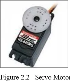
Since standard hobbyist servo motors are meant to use specific voltages (for peak efficiency), most operate at 4.8V to 6V, and their current consumption is similar, the steps for the selection are somewhat simplified. However, it may find a servo motor as shown in Figure 2.2 that operates at 12V; it is important to do additional research about a servo motor controller if the servo motor is not considered “standard”.
Figure 2.2 Servo Motor
8 2.2.3 Stepper Motor Control
A stepper motor as shown in Figure 2.3 is controller type accordingly, though a growing number are able to control both types. The number of leads is usually a dead give-away of the motor type: if the motor has 4 leads, then it is bipolar; should it have 6 or more leads, then it is unipolar.
Figure 2.3 Stepper Motor
9
2.3 PREVIOUS RESEARCH
Before beginning the process of designing a h-bridge circuit, some of the existing circuit should be learn.
2.3.1 Working and Analysis of the H– bridge Motor Driver Circuit Designed for Wheeled Mobile Robots from Vibhor Gupta, University Institute of Engineering and Technology, Panjab University, Chandigarh (2000).
Figure 2.4 H- Bridge Motor Driver Circuit
Simulation and construction of circuits, National instruments Multisim
10 The DC geared motor will work in two directions (Clockwise or anticlockwise) depending upon the direction of flow of current from it. The Inputs A and B will be fed from the microcontroller PIC 16F 877A [2] refer Figure 2.4. Transistors Q1 and Q4 and transistors Q2 and Q3 are given the same input. When A is HIGH, while B is LOW, transistors Q2 and Q3 triggers making the movement of the motors in one direction. Similarly when A is LOW, while B is HIGH, transistors Q1 and Q4 triggers making the direction of the motor opposite.
The transistors used are BD 139(NPN) and BD 140(PNP) as shown in Table 2.2. These are power transistors which are able to withstand the high starting current of the motors due to starting torque from the gears, unlike simple BJT‟s.
TABLE 2.1 Characteristics of BD 139 and BD 140 [3]
Symbol Parameter Max. Unit
VCBO Collector-base voltage 100 V
VCBO Collector-emitter voltage 80 V


![TABLE 2.1 Characteristics of BD 139 and BD 140 [3]](https://thumb-ap.123doks.com/thumbv2/123dok/485665.53320/24.612.182.474.335.491/table-characteristics-bd-bd.webp)
