i
THE APPLICATION OF DIFFERETIAL BOX-COUNTING METHOD FOR IRIS RECOGNITION
AHMAD AZFAR BIN MAHMAMI
This Report Is Submitted In Partial Fulfillment of the Requirements for the Award Of Bachelor of Electronic Engineering (Computer Engineering) With Hounors
Faculty of Electronic and Computer Engineering Universiti Teknikal Malaysia Melaka
ii
UNIVERSTI TEKNIKAL MALAYSIA MELAKA
FAKULTI KEJURUTERAAN ELEKTRONIK DAN KEJURUTERAAN KOMPUTER
BORANG PENGESAHAN STATUS LAPORAN
PROJEK SARJANA MUDA II
Tajuk Projek : The Application of Differential Box-Counting Method for Iris Recognition
Sesi Pengajian : 1 4 / 1 5
Saya AHMAD AZFAR BIN MAHMAMI
mengaku membenarkan Laporan Projek Sarjana Muda ini disimpan di Perpustakaan dengan syarat-syarat kegunaan seperti berikut:
1. Laporan adalah hakmilik Universiti Teknikal Malaysia Melaka.
2. Perpustakaan dibenarkan membuat salinan untuk tujuan pengajian sahaja.
3. Perpustakaan dibenarkan membuat salinan laporan ini sebagai bahan pertukaran antara institusi pengajian
tinggi.
4. Sila tandakan ( √ ) :
SULIT*
*(Mengandungi maklumat yang berdarjah keselamatan atau kepentingan Malaysia seperti yang termaktub di dalam AKTA RAHSIA RASMI 1972)
TERHAD** **(Mengandungi maklumat terhad yang telah ditentukan oleh organisasi/badan di mana penyelidikan dijalankan)
TIDAK TERHAD
Disahkan oleh:
__________________________ ___________________________________
iii
“I hereby declare that this report is the result of my own work except for the quotes as cited in the references”
Signature :
iv
“I hereby declare that I have read this report and in my opinion this report is sufficient in terms of the scope and quality for the award of Bachelor of Electronic Engineering
(Computer Engineering) With Honors”
Signature :
v
A special dedication to my parents, Mr. Mahmami Bin Alias and Mrs. Azizah Binti Abdul Aziz for giving me a moral support, for my supervisor Puan Norazlina Binti Abdul Razak for supervise teaching me during my final year project studies, and thanks
vi
ACKNOWLEDGEMENT
I would like to express my grateful to Allah S.W.T for blessing me with a good health, knowledge and strength to finish my thesis writing and final year project successfully.
My special thanks to my supervisor, Puan Norazlina Binti Abdul Razak for conducting me during this final year project studies. A lots of help, guidance and knowledge provided by her, helping me a lot during my final year project studies.
I would like to thanks to my parents for their support especially moralty support throughout my studies. They have been my inspiration since I started my degree studies in Universiti Teknikal Malaysia Melaka. This thesis is a part of their contribution.
vii
ABSTRACT
viii
ABSTRAK
ix
TABLE OF CONTENT
CHAPTER TITLE PAGE
TITLE i
SUPERVISOR CONFIRMATION ii
ACKNOWLEDGEMENT vi
ABSTRACT vii
ABSTRAK viii
TABLE OF CONTENT x
LIST OF FIGURES xi
I INTRODUCTION
1.1 PROJECT INTRODUCTION 1
1.2 OBJECTIVES 2
1.3 PROBLEM STATEMENT 2
1.4 SCOPE OF PROJECT 3
1.5 PROJECT LIMITATION 3
1.6 REPORT STRUCTURE
II LITERATURE REVIEW
2.1 INTRODUCTION 5
2.2 IRIS RECOGNITION SYSTEM 7
2.2.1 IMAGE ACQUISITION 7
2.2.2 SEGMENTATION 8
2.2.3 NORMALIZATION 9
2.2.4 FEATURE ENCODING 10
2.2.5 MATCHING 11
x
2.4 DIFFERENTIAL BOX-COUNTING METHOD 13
III RESEARCH METHODOLOGY
3.1 PROJECT PLANNING 18
3.2 GANTT CHART 19
3.3 PROJECT FLOWCHART 20
3.4 IMAGE PREPROCESSING 21
3.5 FEATURE EXTRACTION 21
3.6 NEURAL NETWORK CLASSIFICATION 21
3.7 MATLAB SIMULATION 21
IV RESULT & DISCUSSION
4.1 AUTOMATIC IRIS SEGMENTATION 26
4.2 FEATURE EXTRACTION 33
4.3 NEURAL NETWORK 36
4.4 ANALYZE PERFORMANCE 39
V CONCLUSION & RECOMMENDATION
5.1 CONCLUSION 41
5.2 RECOMMENDATION 42
REFERENCES 44
APPENDIX A 45
xi
LIST OF FIGURE
NO TITLE PAGE
2.1 Example of iris pattern 6
2.2 Iris recognition system 7
2.3 Sample of iris imeges from CASIA 8
2.4 Iris segmentation 8
2.5 Rectangular representation of an iris 9
2.6 Feature encoding 10
2.7 Example of iris image has been transformed into fractal image 12 2.8 Index value between Euclidean and fractal 12 2.9 Example of DBC method application for determining the 13
number of boxes
2.10 Example of DBC method application with boxes 14
2.11 Example of Richardson’s Plot 16
2.12 Example of comparing the complexity between three 16 methods (DBC, Gangepain and Keller)
2.13 Example of comparing the number of computations 17 between five methods
3.1 Gantt chart 19
3.2 Project flowchart 20
3.3 Step to use the neural network classification in MATLAB 22
4.1 Original eye and the find circle eye 27
4.2 Iris circle converted into a rectangular pattern 27 4.3 The good and the poor segmentation result 28
xii
4.5 Fail iris region 30
4.6 Correct iris segmentation 31
4.7 Fail iris segmentation 32
4.8 Selecting the iris region to be calculated 33
4.9 Value of Fractal Dimension for an image 34
4.10 Input data stored in Excel 34
4.11 Output target in Excel 35
4.12 Import the input and output data 36
4.13 Data used for validation, training and testing 37
4.14 Neural Network architecture 37
4.15 Training, validation and testing results 38
4.16 Confusion plot 39
1
CHAPTER 1
INTRODUCTION
1.1 Project Introduction
Private information is normally provided by using passwords or Personal Identification Numbers (PINs) for authentication, which are easy to implement, but it is exposed to probability that user forgotten their password. Biometric technology, which is uses human physiological character for personal identification, is a more effective alternative to replace the PIN based authentication techniques [1]. In biometrics nowadays, iris recognition is a type of physical identification that is based on the personal and unique characteristics of the iris, the colored ring around the pupil of an eye. Similar to the more common fingerprint recognition, iris recognition is based on scanning a person's iris and comparing the scan to a stored photograph or template to make an identification match [2].
2
The iris image database will be computed in order to find the estimation fractal dimension of the image. The methods that can be used for image fractal dimension estimation are such as Hausdorff dimension, counting dimension, differential box-counting method and many more. The box-box-counting method is widely used because of it's computability and conveniently. In those methods based on box-counting dimension estimation, the main methods are the differential box-counting method (DBCM) and probability method (PM), while differential box-counting method is more widely applied [5].
1.2 Objectives of this project
The main goal of this project is to use the differential box-counting method in the iris recognition system. Specifically, the main objectives of this project are:
a) To apply the application of differential box-counting method in iris recognition
b) To evaluate the performance and the accuracy of the differential box-counting method by using neural network.
1.3 Problem Statement
3
1.4 Scope of Project
The scope of this project is to perform the neural network classification and measure the performance of the classification. The neural network classification should result an 80% of accuracy. The iris image database will be obtained at CASIA website. The MATLAB software will be used to program the algorithm to compute the fractal dimension for iris image. To compute the fractal dimension of iris images, the differential box-counting method will be used. About 50-100 iris image database will be computed and also about 10 of humans irises will involve in this research.
1.5 Project Limitation
This project has a limitation of the study. In this project, only about 50-100 iris images and about 10 human irises will be used to perform the neural network classification and fractal dimension. Only MATLAB software will use to perform the neural network classification. For the fractal dimension estimation, only differential box-counting method will be used.
1.6 Report Structure
This thesis is a combination of five chapters that contain the introduction, literature review, methodology, result and discussion and the last chapter is the conclusion and recommendation of the project.
4
Chapter 3 will explain about the project methodologies of the project. This chapter will show the steps and flow for problem solving in such a specific method used to estimate the fractal dimension or feature extraction using the differential box-counting method and the neural network classification in order to find the 80% of accuracy will be focused on.
5
CHAPTER 2
LITERATURE REVIEW
This chapter will explain and discuss about the literature which is related to iris recognition and the implementation method that has been studied from different resources to perform this project.
2.1 Introduction
6
Figure 2.1: Example of iris pattern
As a vital and different trademark for status, the iris has numerous focal points, for example, uniqueness, steadiness, and many more. Non-contacting biometrics are the unavoidable pattern of the examination and the advancement of status identification. The error rate of iris distinguish is the most minimal in all the biometrics as indicated by the statistic [7].
To enhance the accuracy, the vast majority of the biometric verification system store numerous templates for every user to record for varieties in biometric information. Consequently, these systems may experience the problem of not enough storage room and computational overheads. With a specific end goal to address these issues, the system must be monitored and upgrade if needed and optimize the computational by making a solid example, an iris format for every user instead of keeping up numerous templates [9].
7
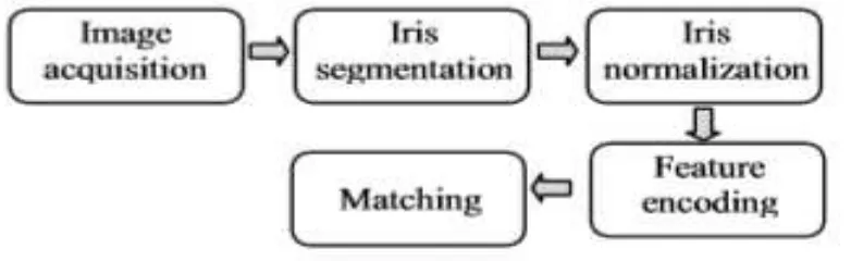
2.2 Iris Recognition System
The iris recognition process consists of 5 major steps. The first step is the image acquisition of a person's eye at enrollment time or check the time. The second step is to segment the iris out of the image containing the eye and part of the face, which localizes the iris pattern. Step three is the normalization; here the iris pattern will be extracted and scaled to a predefined size. Step four is the template generation, here the details of the iris are filtered, extracted and represented in an iris code. The last step is the matching phase, where two iris codes will be compared and a similarity score are computed [9] [10]. These steps are shown schematically in Figure 2.2.
Figure 2.2: Iris recognition system
2.2.1. Image acquisition
8
Figure 2.3: Sample of iris images from CASIA
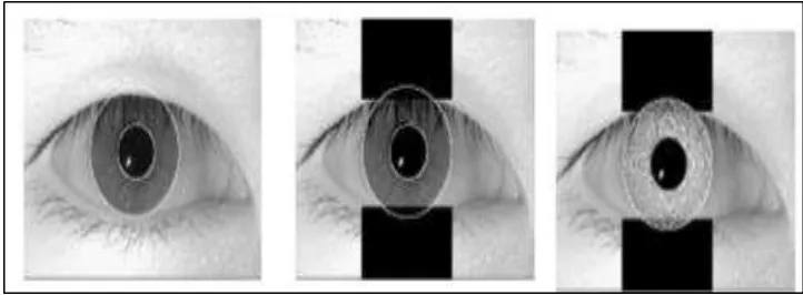
2.2.2. Segmentation
A good segmentation algorithm should involve two procedures, iris localization and noise reduction. The iris localization processes take the acquired image and find both the boundary between the pupil and iris, and the boundary between the iris and the sclera. The noise reduction process refers to localizing the iris from the noise (non-iris parts) in the image. These noises include the pupil, sclera, eyelids, eyelashes, and artifacts. Figure 2.4 shows the iris segmentation step [9] [10].
9
2.2.3. Normalization
Once the iris region has been duly segmented from a given image, it becomes important to organize its information to enable future comparisons. For the processing of an accurate match, it is essential to have in one database, images which contain the same dimensions. However, some factors contribute to dimensional inconsistencies such as varying imaging distance and also the stretching of the iris caused by pupil dilatation from varying levels of illumination. Other sources of inconsistency include a possible rotation of the camera, head tilt, and rotation of the eye within the eye socket. Another point to note is that the pupil region is not always concentric within the iris. Normally the pupil presents a slightly nasal position, that is, the pupil’s center is at a lower position than that of the iris’ center and closer to the nose. The normalization process is responsible for the generation of images with fixed dimensions, and so, images of the same iris captured under different conditions will have characteristic features at the same spatial location. John Daugman has proposed a method to generate a rectangular representation of the ring shaped iris region through a dimensional polar coordinates. This representation shows in the figure 2.5 [9] [10].
Figure 2.5: Rectangular representation of an iris
10
the vertical dimension of the rectangular representation. The number of radial lines represents the angular resolution and defines the horizontal dimension of the rectangular representation. This method takes into account pupil dilatation, imaging distance and non-concentric pupil displacement [9] [10].
2.2.4. Feature Encoding
In the feature encoding step, a template representing iris pattern information is created using a Gabor filter, log Gabor filter or zero-crossing of the wavelet transform. The differences in lighting between two different images cause error when directly comparing the pixel intensity of two different iris images. To alleviate this difficulty, Duagman extracted the features from the normalized iris image by using convolution with 2-D Gabor filters. In that system, the filters are multiplied by the raw image pixel data and integrated over their domain of support to generate coefficients which describe, extract, and encode image texture information. A noise mask associated with the feature template is generated to mark the corrupted bits in the template, Figure 2.6 [9] [10].
11
2.2.5. Matching
The goal of matching is to evaluate the similarity of two iris representations. Created templates are compared using the Hamming distance or Euclidean distance. The normalized Hamming distance used by Daugman measures the fraction of bits in which two iris codes disagree. A low normalized Hamming distance implies strong similarity of the iris codes. If parts of the irises are occluded, the normalized Hamming distance is the fraction of bits that disagree in the areas that are not occluded on either image. To account for rotation, a comparison between a pair of images involves computing the normalized Hamming distance for several different orientations that correspond to circular permutations of the code in the angular coordinate. The minimum computed normalized Hamming distance is assumed to correspond to the correct alignment of the two images [9] [10].
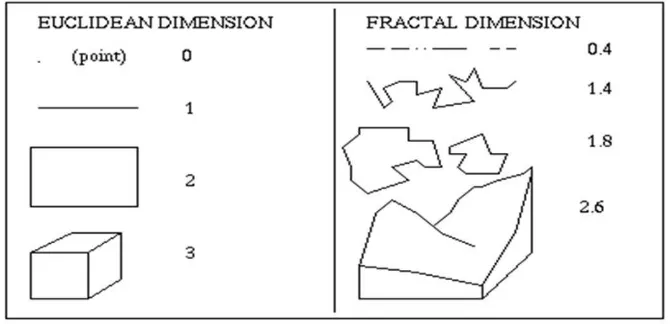
2.3 Fractal Dimension
12
Figure 2.7: Example of iris images has been transformed into fractal image
Figure 2.8: Index value between Euclidean and fractal dimension