The effects of Mg addition on the microstructure and mechanical
properties of thixoformed Al–5%Si–Cu alloys
M.S. Salleh
a,b, M.Z. Omar
a,⇑, J. Syarif
aaDepartment of Mechanical and Materials Engineering, Faculty of Engineering and Built Environment, Universiti Kebangsaan Malaysia, 43600 Selangor, Malaysia b
Department of Manufacturing Process, Faculty of Manufacturing Engineering, Universiti Teknikal Malaysia Melaka, Hang Tuah Jaya, 76100 Durian Tunggal, Melaka, Malaysia
a r t i c l e
i n f o
Article history: Received 17 July 2014
Received in revised form 17 September 2014
Accepted 19 September 2014 Available online 2 October 2014
Keywords: Al–Si–Cu alloy Thixoforming T6 heat treatment Mechanical properties
a b s t r a c t
In this study, the effects of different amounts of magnesium (Mg) on the microstructures and tensile properties of thixoformed Al–5%Si–Cu alloys were investigated. Three different alloys containing various amounts of Mg (0.5, 0.8 and 1.2 wt%) were prepared through the cooling slope casting technique, before they were thixoformed using a compression press. Several of the thixoformed samples were then treated with a T6 heat treatment, that is, solution treatment at 525°C for 8 h, quenching in warm water at 60°C, followed by aging at 155°C for 4 h. All of the samples were then characterised by optical microscopy (OM), scanning electron microscopy (SEM) energy dispersive X-ray (EDX) spectroscopy and X-ray diffraction (XRD) analysis as well as by tensile tests. The results revealed that magnesium was able to refine the size ofa-Al globules and the eutectic silicon in the samples. It was also observed that a compact p-Al9FeMg3Si5phase was formed when the magnesium content was 0.8 wt% and 1.2 wt%. The mechanical properties of the thixoformed alloys improved significantly after the T6 heat treatment. The highest attainment was recorded by the latter alloy (i.e. with 1.2 wt%Mg) with its ultimate tensile strength (UTS) as high as 306 MPa, yield strength (YS), 264 MPa, and elongation to fracture of 1.8%. The fracture of thixoformed alloy with a low Mg content (0.5 wt%) showed a combination of dimple and cleavage fracture, whereas in the alloy that contained the highest Mg content (1.2 wt%), cleavage fracture was observed.
Ó2014 The Authors. Published by Elsevier B.V. This is an open access article under the CC BY-NC-ND license (http://creativecommons.org/licenses/by-nc-nd/3.0/).
1. Introduction
Semisolid metal (SSM) processing is a near-net-shape processing method used particularly in the production of automotive compo-nents. This technology offers some advantages such as prolonged die life due to low thermal shock and large laminar cavity fill which could lead to reduced gas entrapment[1–3]. In recent years, the need to produce a product, that is superior in mechanical properties over those using conventional casting (e.g. permanent mould cast-ing), has drawn attention towards SSM processing. One type of SSM processes is thixoforming which involves the preparation of a feedstock alloys followed by re-heating to semisolid temperature to provide SSM slurry subsequently used for component shaping. Over the past few years, there has been extensive interest in the development of new aluminium alloys that are applicable for SSM processing[4,5]. Some of these alloys exhibit good thixoformability such as relatively low sensitivity of the liquid fraction, a suitable
melting range[6]and potential for age hardening[7,8]. However, to date, only a few commercially available cast aluminium alloys have been selected for SSM processing, such as A319, A356 and A357, for the production of commercial products and mainly in the automotive industry [9]. Therefore, there is a demand for expanding the range of aluminium alloys that can be used in this process[10].
The starting material for thixoforming must contain solid globules suspended in a liquid matrix[11]and the globules should consists of both a small size and a high sphericity of the primary
a
-phase[12]. In this state, an alloy can be handled as a solid when at rest, and flow like liquid when it is sheared during the forming pro-cess[13]. Many techniques for producing non-dendritic feedstock for thixoforming have been introduced, a comprehensive review of which can be found in[14]. Among these techniques is a cooling slope (CS) casting process that can produce a non-dendritic micro-structure requiring very little equipment and a low running cost [15,16]. In this method, molten alloys at a superheated temperature is cast over an inclined cooling plate and subsequently solidified into a die[17,18]. The ingot thus obtained exhibits a thixotropic behaviour when reheated to the semisolid temperature. Varioushttp://dx.doi.org/10.1016/j.jallcom.2014.09.152
0925-8388/Ó2014 The Authors. Published by Elsevier B.V.
This is an open access article under the CC BY-NC-ND license (http://creativecommons.org/licenses/by-nc-nd/3.0/).
⇑ Corresponding author. Tel.: +60 3 8911 8010; fax: +60 3 8925 2546. E-mail addresses:[email protected](M.S. Salleh),[email protected](M.Z. Omar),[email protected](J. Syarif).
Contents lists available atScienceDirect
Journal of Alloys and Compounds
parameters such as the pouring temperature, cooling slope length and cooling slope angle can affect the final microstructure[19].
Paes and Zoqui[3]investigated the effects of silicon (Si) and magnesium (Mg) content on the structure and rheological behav-iour of Al–Si–Mg alloys. The researchers’ work focused on the development of new aluminium alloys that are suitable for thixo-forming. In 2008, Birol [20] studied the effects of adding Si to A380 alloy and used low superheat casting (LSC) as a feedstock production method. The hardness of the thixoformed samples increased to up 96 HB as the Si content reached up to a maximum of 20 wt%. In 2011, Shabestari and Parshizfard[21]examined the effects of iron (Fe) and manganese (Mn) content on A380 thixo-formed alloys. In this experiment, the thixoforming feedstock was prepared through the recrystallisation and partial melting (RAP) processing route. The results revealed that the tensile prop-erties of the thixoformed samples were higher than those of A380 alloy. Moreover, the yield strength of the thixoformed samples increased and the ultimate tensile strength decreased as the iron content was increased up to a maximum 2.87 wt%.
Magnesium (Mg) is an alloying element that is usually added to Al–Si–Cu casting alloys to enhance the mechanical properties of the alloys[22]. Iron (Fe), manganese (Mn) and zinc (Zn) are consid-ered as impurities in most Al–Si–Cu alloys. During solidification, various constituent particles were formed including Mg2Si, Al2Cu, Al5Cu2Mg8Si6,b-Al5FeSi, Al8Mg3FeSi6, Al15(Mn, Fe)3Si2under vari-ous conditions[23–26]. In alloys containing Cu and/or Mg, T6 heat treatment is usually applied to improve the mechanical properties of the alloys[27]. Although a high content of Mg increases the strength of Al–Si–Cu alloys, the formation of a large Mg2Si phase of about 4–8
l
m during the solidification of conventional cast alloys is detrimental to the alloys’ ductility[1,28]. By contrast, it is expected that the size of Mg2Si phase is refined in thixoformed alloys due to the lower processing temperature used (560– 580°C) compared to that applied in the conventional casting process (660–700°C)[1,29].Although the effects of Mg on the microstructure of conven-tional cast Al–Si–Cu alloys have been frequently reported in the literature, reports on the effects of Mg on the microstructure and mechanical properties of thixoformed Al–Si–Cu is still lacking. Therefore, there is a significant need to investigate this alloy for thixoformed processing, to realise and exploit its full advantages. In this study, experimental work was carried out to evaluate the microstructural features and mechanical properties of thixoformed Al–5%Si–Cu alloys with different Mg contents (0.5 wt%, 0.8 wt% and 1.2 wt%). Three different alloys were produced using a cooling slope casting method, before they were thixoformed using a com-pression press. A T6 heat treatment schedule was also applied to some of the thixoformed samples. The samples’ tensile properties and fracture behaviour were also analysed.
2. Experimental procedures
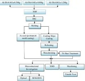
The alloys Al–5Si–0.8Cu–xMg (x= 0.5, 0.8 and 1.2 wt%) used in this study were fabricated via a conventional casting process. The X-ray fluorescence (XRF) is used to determine their chemical compositions, the results of which are coded as alloys A, B and C respectively, as shown inTable 1. The process flow for this experimental procedure is shown inFig. 1. Differential scanning calorimetry (DSC) was performed to estimate the solidus, liquidus temperature (Table 2) and liquid fraction profiles within the semisolid temperature of the alloys. The alloys were sectioned into small pieces (approximately 40 mg) for testing with a Netzsch-STA (TG-DSC) 449 F3 simultaneous thermogravimeter. The DSC analyses were carried out in a nitrogen atmosphere with a scanning rate of 10°C/min to prevent oxidation. The liquid
fraction of the alloys as a function of temperature was determined from heat flow versus temperature curves, as shown inFig. 2.
Table 1
Chemical composition of studied alloys (wt.%).
Alloy code Si Cu Mg Ni Zn Mn Fe Al
A (Al–5Si–Cu–0.5 Mg) 4.94 0.86 0.51 0.03 0.02 0.11 0.54 Remainder B (Al–5Si–Cu–0.8 Mg) 4.91 0.83 0.81 0.02 0.01 0.08 0.41 Remainder C (Al–5Si–Cu–1.2 Mg) 4.94 0.81 1.21 0.03 0.05 0.10 0.43 Remainder
DSC
Melting
Cooling Slope Casting
Reheating
Thixoforming T6 Heat Treatment As-cast (permanent
mold casting)
SEM-EDX
Tensile Test
Optical
Microstructural Investigation
XRD Machining
XRF
Al-5Si-0.8Cu-0.8Mg Al-5Si-0.8Cu-1.2Mg Al-5Si-0.8Cu-0.5Mg
The starting materials were subjected to the cooling slope (CS) casting process-ing route to prepare suitable feedstock for thixoformprocess-ing. A mass of 1.2 kg of the alloys was superheated at 700°C in a silicon carbide crucible located inside a resis-tance furnace in an argon atmosphere to prevent oxidation, and then cooled to the selected temperatures (i.e. 640–660°C) before being poured onto the surface of a 90-mm-wide inclined plate made of stainless steel (6 mm thick); various plate lengths were used, as listed inTable 3. The temperature for this experiment was selected to be above the liquidus temperature obtained by DSC. The cooling slope length and pouring temperature combinations ofTable 3were tested on Alloy A to study its morphological evolutions. The tilt angle (60°) of the cooling slope was constant for all the experiments to reduce the adhesion of the solidified alloy during its flow on the cooling slope plate. The plate was cooled with water to increase the nucleation rate of thea-Al particles and thereby produce a fine and less dendritic microstructure. The surface of the cooling slope plate was coated with a thin layer of boron nitride to prevent the adhesion of the molten alloy.
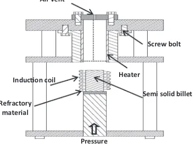
After pouring, the melt became semisolid at the end of the cooling plate and was then solidified in a 150°C preheated cylindrical stainless steel mould with a diameter of 30 mm and a depth of 155 mm. An as-cast (permanent mould casting) sample obtained at a pouring temperature of 700°C was poured directly into similar mould preheated to 150°C. For thixoforming, samples with the best shape factor and globule size were selected and were sectioned to dimensions of Ø 30120 mm; the section samples were then reheated to a semisolid state and thi-xoformed into a die (Fig. 3). The dimensions of the cylindrical billets after forming were Ø 3590 mm.
A high-frequency induction coil (30–80 kHz, 35 kW) placed under the die was used to heat the ingots into a semisolid temperature range. The die in the thixoforming unit was preheated to 300°C. The heating was monitored using a cal-ibrated K-type thermocouple located 8 mm from the top of the slug. Argon gas was flowed at 2.5 l/min in the thixoforming press, which was topped with a stainless steel cover to prevent oxidation during thixoforming. Measurements were taken to achieve rapid heating at 130°C/min in order to prevent grain growth. The spec-imens were rapidly reheated to 578°C, 572°C and 570°C for alloys A, B and C,
respectively for 5 min to allow for spheroidisation of the grains. The thermocouple was withdrawn from each specimen, and the compression process was carried out
using a hydraulic cylinder press that provided a load of 20 kN and had a maximum compression velocity of 85 mm/s. The applied pressure was held for 15 s during pressing the specimens. Some of the as-cast and as-thixoformed parts were subjected to aT6 heat treatment in a furnace equipped with a programmable temperature controller for both the solution heat treatment and the ageing heat Table 2
Solidus and liquidus temperature of the studied alloys.
Alloy Solidus temperature (°C) Liquidus temperature (°C)
A 533 635
B 536 633
C 541 628
0 10 20 30 40 50 60 70 80 90 100 0 10 20 30 40 50 60 70 80 90 100 0 10 20 30 40 50 60 70 80 90 100 0 0.2 0.4 0.6 0.8 1 1.2 0 0.2 0.4 0.6 0.8 1 1.2
500 520 540 560 580 600 620 640
Heat flow (mW)
Heat flow (mW)
Heat flow (mW)
Temperature (°C)
Temperature (°C) Temperature (°C)
DSc curve DSc curve Liquid fraction profile Liquid fraction profile DSc curve Liquid fraction profile
Liquid fraction (%)
Liquid fraction (%) Liquid fr
actio
n
(
%
)
a
b
c
highest Knee
highest Knee highest Knee
2 1.8 1.6 1.4 1.2 1 0.8 0.6
490 510 530 550 570 590 610 630 490 510 530 550 570 590 610 630
Fig. 2.DSC curve and liquid fraction profile (a) alloy A (b) alloy B and (c) alloy C. Table 3
Cooling slope parameters for alloy A.
Tilt angle° Cooling slope length (mm) Pouring temperature (°C)
60 300 640
300 650
300 660
60 400 640
400 650
400 660
60 500 640
500 650
500 660
Heater
Semi solid billet InducƟon coil Screw bolt Pressure Refractory material Air vent
treatment. The solution heat treatment was carried out over a period of 8 h at 525°C. The solution heat-treated samples were quenched in warm water at 60°C and then aged at 155°C for 4 h.
The microstructures of the samples were examined with an Olympus optical microscopy (OM), and the various phases of the samples were identified using a Carl Zeiss (EvoMa10) scanning electron microscope (SEM) equipped with attachments for energy dispersive X-ray (EDX) spectroscopy and X-ray diffraction (XRD) analysis. Moreover, image analysis, i.e. the calculation of the shape factor (SF) and globule size (GS), of thea-Al phase in the CS casting was carried out using Image-J software pro-gram. The shape factor was defined as 4pA/P2, wherePis the perimeter andAthe area of a particle (the shape factor of a circle is equal to one)[30]. The average size of the primary particles was defined as [R2(Ai/p)1/2]/N, whereAiis the area of each particle andNis the total number of particles in each image[31]. The samples for OM and SEM were prepared via the standard grinding technique, using silicon carbide (SiC) abrasive paper and polishing with a LECO microid diamond compound (6lm, 3lm followed by 1lm), and then etched for approximately 20 s with Keller’s reagent.
Cylindrical tensile specimens with a gauge dimension of 20 mm were machined from the as-cast, as-thixoformed and thixoformed T6 samples according to the ASTM: E8M standard. The tensile tests were conducted at room temperature using a 100 kN Zwick Roell Universal Testing Machine (UTM). Three tensile tests were performed from the as-cast, as-thixoformed and thixoformed T6 samples to obtain reliable tensile testing results. An extensometer was attached to the tensile speci-mens to measure the alloy ductility. The yield stress was based on a 0.2% plastic strain offset. After the tensile test, each specimen was sectioned into smaller sec-tions for microscopic observation. The specimens were inspected using a Carl Zeiss SEM at 800X and 2000X magnifications.
3. Results and discussions
3.1. Cooling slope casting and isothermal heating experiment
The optical microstructure of the as-cast of alloy A is illustrated in Fig. 4a. The microstructural features exhibit typical
a
-Alb
a
Fig. 4.Microstructures of the alloy A (0.5 wt%Mg) (a) as-cast and (b) cooling slope casting.
0 0.2 0.4 0.6 0.8 1
300 400 500
Shape Factor
Length on the cooling slope (mm)
Poured at 640°C Poured at 650°C Poured at 660°C
5 10 15 20 25 30 35 40 45 50
300 400 500
Globule size (µm)
Length on the cooling slope (mm)
Poured at 640°C Poured at 650°C Poured at 660°C
a
b
Fig. 5.Variations in the (a) shape factor and (b) globule size ofa-Al particles for alloy A (0.5 wt%Mg) relative to the pouring temperature and cooling slope length.
a b
Fig. 6.Microstructures of ingots cast over cooling slope plate at 650°C and 400 mm cooling length (a) alloy B (0.8 wt%Mg), and (b) alloy C (1.2 wt%Mg). Table 4
Semisolid process parameters for the materials of the present study.
Alloy Reheating temperature (°C) Reheating time (min)
A 578 5
B 572 5
dendrites and very fine interdendritic structures of the Al–Si eutectic throughout the sample.Fig. 4b shows the microstructural features of alloy A after cast over the cooling slope plate from a
pouring temperature of 650°C with a cooling slope length of 400 mm. As shown inFig. 4b, the changes in the primary phase mor-phology after the cooling slope casting was very clear, and all of the
a
b
c
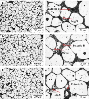
Fig. 7.Optical micrographs of the alloys after isothermal heating at different temperatures for 5 min (a) alloy A (0.5 wt%Mg), (b) alloy B (0.8 wt%Mg) and (c) alloy C (1.2 wt%Mg).
Mg2Si
Mg
2Si
Mg
2Si
Eutectic Si
a
b
c
Eutectic Si
Eutectic Si
dendritic microstructure was replaced by
a
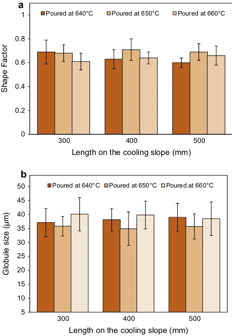
-Al globule and rosette. Fig. 5shows a variation in the shape factor and globule size of var-ious pouring temperatures and cooling slope lengths used for alloy A. For the pouring temperature of 640°C, cooling slope length of 300 mm has generated a more spherical and smallera
-Al particle size than those generated by the 400 and 500 mm long slopes. When pouring at 650°C, cooling slope length of 400 mm shows betterresults than the 300 and 500 mm long slopes, while pouring at 660°C yielded better results at the cooling slope length of 500 mm. The results indicate that for each pouring temperature, there was an optimum slope length for which the most refined and near globular microstructure was obtained. The best micro-structural features for feedstock preparation sample was obtained with a pouring temperature of 650°C and a cooling slope length of 400 mm to transform the fully dendritic structure into a spherical one with a globule size of 34.9 ± 6.1
l
m and shape factor of 0.7 ± 0.10. However, the difference in both shape factor and globule size for all the combinations of pouring temperatures and slope lengths used is trivial, indicating the simplicity and flexibility of the cooling slope method in producing suitable aluminium alloy feedstocks for thixoforming. Therefore, the same combination of pouring temperature and slope length was used for alloys B and C. Fig. 6shows the microstructures for these two alloys after cooling slope casting.The cooling slope casting samples were sectioned and heated in an induction coil to the reheating temperature listed inTable 4, before they were quenched in water. These temperatures were estimated from the liquid fraction versus temperature curve in Fig. 2. The microstructures of the cooling slope casting after being isothermally held for 5 min are shown in Fig. 7. The average globule size of the alloys A, B and C before and after reheating at the temperatures as inTable 4were (34.9 ± 6.1
l
m, 33.8 ± 6.5l
m and 32.1 ± 5.1l
m) and (53.2 ± 4.1l
m, 52.9 ± 4.8l
m and 50.6 ± 3.6l
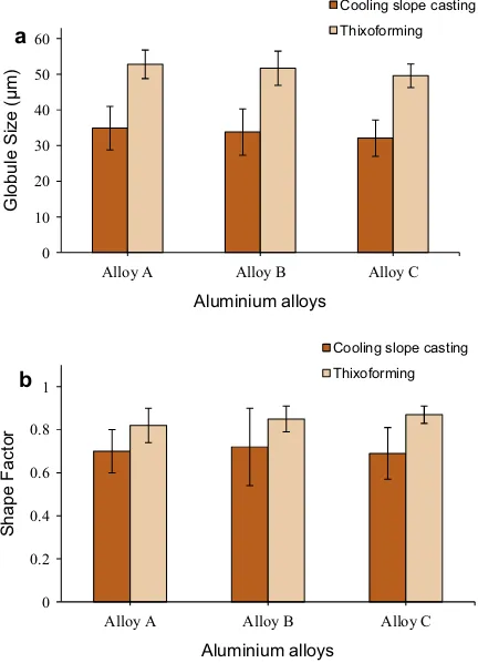
m) respectively, implying substantial coarsening during isothermal holding at respective temperatures.3.2. Microstructures of thixoformed samples
Previous work has shown that a liquid content of 30–50% is required in a feedstock material for thixoforming[4,32]. Hence, in this work, thixoforming was carried out at a liquid content of approximately 45%, which corresponded to 578°C, 572°C and 570°C for the alloys A, B and C respectively. The alloys were thixo-formed after being heated in situ at the respective temperatures in a compression press. As illustrated inFig. 8, the thixoformed sam-ples showed a uniform distribution of nearly globular
a
-Al grains, and no micro pores were observed throughout the samples. The 010 20 30 40 50 60
Alloy A Alloy B Alloy C
Globule Size (µm)
Aluminium alloys
Cooling slope casting
Thixoforming
0 0.2 0.4 0.6 0.8 1
Alloy A Alloy B Alloy C
Shape Factor
Aluminium alloys
Cooling slope casting
Thixoforming
a
b
Fig. 9.Variations in the (a) globule size and (b) shape factor in cooling slope casting and thixoformed alloys.
α-Al
Mg
2Si
a
b
c
20 µm 20 µm
20 µm
Si
Si
Si
Mg
2Si
size of
a
-Al globules was higher than those in the cooling slope casting samples. The difference in the globule size of the thixo-formed samples is believed to be due to the appropriate heating rates used in thixoforming, which increased the size of thea
-Al phase and also helped with the rounding of thea
-Al grains throughout the samples. Moreover,Fig. 9a and b indicate that that the size of thea
-Al globule of alloys A, B and C has decreased slightly while the corresponding shape factor slightly increased when the Mg content increases. A few Mg2Si were observed in the microstructure, and the eutectic silicon was more effectively refined in alloy C, relative to that in alloy A and B. As indicated inTable 1, there was no strontium or antimony in the composition of the alloys, which could help modify the morphology of the eutectic silicon phase. Hence, the refinement can be attributed to the further addition of Mg to alloy A. Micrographs of the partstreated with the T6 heat treatment are illustrated inFig. 10. The T6 heat treatment affected the microstructure of the samples, modifying the eutectic Si particles (help to spheroidise the Si eutectic particle) during solid solution strengthening and develop-ing an intra-granular contrast durdevelop-ing agedevelop-ing[33]. The structure of the thixoformed T6 alloys shows a dispersion of fine Si particles embedded between the solid
a
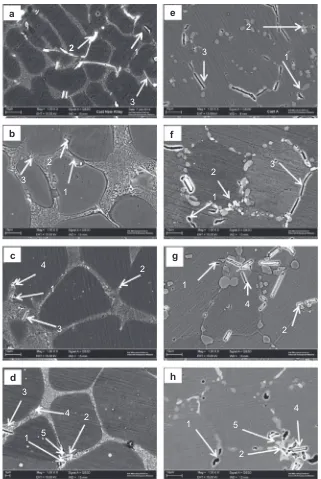
-Al globules.Fig. 11shows SEM images of as-cast, thixoformed and thixo-formed T6 alloys with different Mg contents. As shown inFig. 11, there were five types of intermetallic phases formed in the alloy: Mg2Si, Al2Cu, b-Al5FeSi,
p
-Al9FeMg3Si5 and Al5Cu2Mg8Si5. It is reported that the iron-rich intermetallic compound consists ofb -Al5FeSi,p
-Al9FeMg3Si5 orp
-Al8FeMg3Si6 depending on the Mg content of the alloys[34,35]. The iron-rich intermetallic phase that appeared in the microstructure after the thixoforming process2
1
3
2
1
3
2
1
3
4
a
c
b
d
3
1
4
2
5
e
f
g
h
1
3
2
2
3
1
2
1
4
5
1
4
2
reduced the mechanical properties of the alloys[29]. Moreover, iron is the most harmful impurity in aluminium alloys; indeed, iron can lead to reduced tensile strength and ductility. As the Mg content increased, the
p
-phase was also observed in alloy B and C, as shown in Fig. 11(c and d).p
-Al9FeMg3Si5 had a compact morphology and was less harmful than the acicular b-Al5FeSi [24]. The microstructure of a sample obtained after the T6 heat treatment is shown inFig. 11(e–h). In the thixoformed T6 sample, the particle distribution has improved relative to those of the as-thixoformed sample and the silicon particles have completely transformed into the spheroidal form. Small amounts of Mg2Si were precipitated alongside the silicon particles dispersed homog-enously throughout the samples, which may have improved the mechanical properties of the alloys.3.3. Mechanical properties
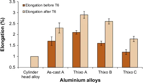
The effect of the addition of Mg on the tensile properties of Al– 5Si–Cu alloy in as-cast, as-thixoformed and thixoformed T6 samples were investigated, and the results are shown inFig. 12. As shown inFig. 12, the ultimate tensile strength (UTS) and yield strength (YS) has increased with the increasing amount of Mg (alloy A; 0.5 wt%Mg, alloy B; 0.8 wt%Mg, alloy C; 1.2 wt%Mg). How-ever, as indicated inFig. 13, the addition of 0.8 wt% and 1.2 wt% of Mg reduced the elongation to fracture of the thixoformed alloys. The reduction in the elongation to fracture of the alloys was nearly
linear with the increase in the Mg content of alloy A. This effect was due to the formation of brittle phases (i.e. Mg2Si,
p
-Al9FeMg3Si5 and Q-Al5Cu2Mg3Si5) that are associated with the Mg content in the alloys[36].T6 heat treatment improved significantly the tensile properties of the alloys. As shown inFig. 12, for the thixoformed alloy A, the UTS, YS and elongation to fracture are 251 MPa, 224 MPa and 2.9%, respectively, while for the alloy B, the corresponding values are 267 MPa, 233 MPa and 2.6%, respectively. For the thixoformed alloy C, the UTS and YS are increased significantly (306 MPa and 264 MPa respectively) while the elongation to fracture decreased to 1.8%. It is evident that increasing the Mg content yielded greater tensile strength in the T6 treated samples, which could be attrib-uted to the formation of more Mg2Si precipitates during T6 heat treatment. The precipitation hardening sequences of the Mg2Si due to the addition of Mg to the Al–Si alloys is as follows[37]:
Saturated solid solution!GP zones!
g
0ðMg2SiÞ !g
ðMg2SiÞThe saturated solid solution was obtained by heating the alumin-ium alloys to their solvus line and then quenching the alloys to form GP zones, consistent and unstable
g
0(Mg2Si) and non-consistentand stable
g
(Mg2Si) intermetallic phase during ageing [29]. Theg
(Mg2Si) phase that was formed at the end of the sequence, made dislocation movement more difficult, and as a result, the tensile strengths of the alloys were increased. On the other hand, this situ-ation led to the reduction in the ductility of the alloys. It is evident fromFig. 13that the elongation to fracture was reduced as the Mg content was increased. Moreover, the formation of different types of Fe-rich compounds associated with the increasing Mg content also contributed to the decrease in the ductility of the alloys[24].It was reported that alloy that is used for fabrication of automo-tive engine blocks and cylinder heads should have tensile proper-ties ranging from 250 MPa to 300 MPa for yield and ultimate tensile strength, respectively, and 1% for elongation[27]. As shown inFigs. 12 and 13, the tensile properties of thixoformed alloy C (1.2 wt%Mg) in T6 condition has achieved the minimum require-ment of automotive cylinder head alloys. Therefore, the result indi-cates the suitability of the alloy as a potential material for automotive application.
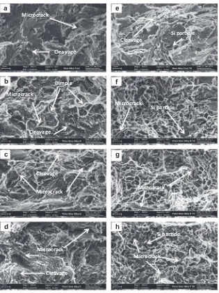
3.4. Fracture behaviour
Fracture surface studies were carried out on the tensile frac-tured samples of the as-cast and thixoformed alloys to provide insight into the various fracture mechanisms that occurred during the tensile testing of the alloys.Fig. 14shows the SEM fractographs of the tensile fracture surface of Al–5Si–Cu with different Mg con-tents in the as-cast, as-thixoformed and heat treated conditions. Fig. 14a illustrates the brittle nature of the samples, as evidenced by the fracture of long Si particles (see white arrow inFig. 14a) in as-cast alloy A. Crack propagation was observed to have occurred between the interdendritic region. In the case of as-thixo-formed alloy A (0.5 wt%Mg), the fractograph inFig. 14b shows a cellular-morphology-type fracture and a small number of dimples, which, in turn, improved the alloy’s ductility relative to that of the alloy in the as-cast condition[38]. For the as-thixoformed alloys B(0.8 wt%Mg) and C (1.2 wt%Mg), the fractographs inFig. 14c and d shows brittle fracture, as evidenced by the cleavage rupture in the alloys.
As mentioned earlier, the T6 heat treatment accelerates the pre-cipitation of fine Mg2Si, which increases the alloy strength. In the case of alloy A in the as-cast T6 condition, depicted inFig. 14e, the Si particles were observed to have been coarser and the cracks were mainly localised in the interdendritic regions. In the case of T6 treated thixoformed alloy A, the fractograph inFig. 14f shows 100 120 140 160 180 200 220 240 260 280 300 320 340 360 380 Cylinder head alloy
As-cast A Thixo A Thixo B Thixo C
St
rength (
MPa)
Aluminium alloys Ultimate tensile strength (UTS)
Ultimate tensile strength (UTS) T6 Yield strength (YS) T6 Yield strength (YS)
Fig. 12.Comparison of ultimate tensile strength and yield strength of the cylinder head alloy, as-cast, thixoformed and thixoformed T6 alloys.
0.5 1 1.5 2 2.5 3 3.5 Cylinder head alloy
As-cast A Thixo A Thixo B Thixo C
Elongation (%)
Aluminium alloys Elongation before T6
Elongation after T6
smaller Si particles with a dimple structure, and the crack occurred by void initiation at the silicon particle, which are believed to have improved the ductility of the alloy. In the case of the T6 treated samples of thixoformed alloys B and C, shown inFig. 14g and h, the fracture samples show ductile fracture, as evidenced by the dimple structure in the alloys. Increasing the Mg content leads to the increase in the amount of precipitate-hardening phase, Mg2Si, resulting with the increase in strength. This is evidenced from the higher number of microcracks seen in the micrograph ofFig. 14h when compared toFig. 14f and g. Crack propagation between
a
-Al grains, which is believed to originate in the Si, Fe and Mg-con-taining phase (see white arrow inFig. 14g and h), reducing the elongation to fracture of thixoformed alloys B and C.4. Conclusions
In this work, the effects of Mg addition at different ratios (0.5 wt%, 0.8 wt% and 1.2 wt%) on the microstructure and mechan-ical properties of thixoformed Al–5Si–Cu aluminium alloy were investigated. Based on the analysis of the results, the following conclusions are drawn:
(1) It is observed that Al–5Si–Cu alloy with a variation in Mg content is tailored for the thixoforming process. Moreover, adding 0.8 wt% and 1.2 wt%Mg resulted in the formation of the
p
-Al9FeMg3Si5 phase, whose morphology is compact compared to that of theb-Al5FeSi phase.(2) The addition of magnesium to Al–5%Si–Cu has slightly refined the size of
a
-Al globule and eutectic silicon in the microstructure of the thixoformed samples.(3) In parallel to the increase in the Mg content, the tensile strength of the alloys increased and the percent elongation values decreased. The T6 treated samples displayed higher ultimate and yield tensile strengths as high as 306 MPa and 264 MPa respectively, when 1.2 wt%Mg was added to the alloys. However, the elongation to fracture was reduced to 1.8%. But these have surpassed the minimum require-ments of certain automotive applications such as the cylin-der heads.
(4) The fracture behaviour of thixoformed alloys with low Mg content showed cellular morphology-type fracture, and a small number of dimples were observed in the samples, whereas the fracture behaviour of thixoformed alloys with
Microcrack
Microcrack Cleavage
Dimple
Cleavage
Cleavage
Microcrack
Cleavage
a
b
c
h
Si parƟcle
e
f
Si parƟcle
g
Microcrack
d
Si parƟcle
Microcrack Microcrack Microcrack
Cleavage
a high Mg content showed brittle-type fracture with cleav-age rapture in the alloys. However, the fracture behaviour of the thixoformed alloys in T6 condition showed a heavily dimpled structure, an indicator of improved material ductility.
Acknowledgements
The authors would like to thank Universiti Kebangsaan Malay-sia (UKM) and the Ministry of Education (MOE), MalayMalay-sia, for the financial support under research Grants GUP-2012-040 and AP-2012-014.
References
[1]A. Abedi, M. Shahmiri, B. Amir Esgandari, B. Nami, J. Mater. Sci. Technol. 29 (2013) 971–978.
[2]A. Fadavi Boostani, S. Tahamtan, J. Alloy. Comp. 481 (2009) 220–227. [3]M. Paes, E.J. Zoqui, Mater. Sci. Eng., A 406 (2005) 63–73.
[4]D. Liu, H.V. Atkinson, H. Jones, Acta Mater. 53 (2005) 3807–3819. [5]J.B. Patel, Y.Q. Liu, G. Shao, Z. Fan, Mater. Sci. Eng., A 476 (2008) 341–349. [6]G. Chen, Z. Du, Y. Cheng, Mater. Des. 35 (2012) 774–781.
[7]M.S. Salleh, M.Z. Omar, J. Syarif, M.N. Mohammed, K.S. Alhawari, Int. J. Math. Comput. Simul. 7 (2013) 286–293.
[8]M. Salleh, M. Omar, J. Syarif, M. Mohammed, SAINS MALAYSIANA 43 (2014) 791–798.
[9]M.S. Salleh, M.Z. Omar, J. Syarif, M.N. Mohammed, ISRN Mater. Sci. 2013 (2013) 9.
[10]M.S. Salleh, M.Z. Omar, J. Syarif, M.N. Mohammed, Adv. Sci. Lett. 19 (2013) 3503–3507.
[11]M.Z. Omar, H.V. Atkinson, A.A. Howe, E.J. Palmiere, P. Kapranos, M.J. Ghazali, J. Mater. Sci. 44 (2009) 869–874.
[12]K.N. Campo, C.T.W. Proni, E.J. Zoqui, Mater. Charact. 85 (2013) 26–37. [13]M.Z. Omar, H.V. Atkinson, P. Kapranos, Metall. Mater. Trans. A 42 (2011)
2807–2819.
[14]M.N. Mohammed, M.Z. Omar, M.S. Salleh, K.S. Alhawari, P. Kapranos, Sci. World J. 2013 (2013) 16.
[15]Y. Birol, J. Mater. Process. Technol. 186 (2007) 94–101. [16]H.V. Atkinson, Solid State Phenom. 192–193 (2012) 16–27. [17]T. Haga, S. Suzuki, J. Mater. Process. Technol. 118 (2001) 169–172. [18]M.S. Salleh, M.Z. Omar, J. Syarif, K.S. Alhawari, M.N. Mohammed, Mater. Des. 64
(2014) 142–152.
[19]F. Taghavi, H. Saghafian, Y.H.K. Kharrazi, Mater. Des. 30 (2009) 115–121. [20]Y. Birol, J. Mater. Sci. 43 (2008) 3577–3581.
[21]S.G. Shabestari, E. Parshizfard, J. Alloy. Comp. 509 (2011) 7973–7978. [22]C.T. Wu, S.L. Lee, M.H. Hsieh, J.C. Lin, Mater. Charact. 61 (2010) 1074–1079. [23]M.F. Ibrahim, E. Samuel, A.M. Samuel, A.M.A. Al-Ahmari, F.H. Samuel, Mater.
Des. 32 (2011) 2130–2142.
[24]A.M.A. Mohamed, F.H. Samuel, S. Al kahtani, Mater. Sci. Eng., A 543 (2012) 22–34.
[25]A.M. Samuel, H.W. Doty, S. Valtierra, F.H. Samuel, Mater. Des. 53 (2014) 938–946.
[26]C.H. Cáceres, M.B. Djurdjevic, T.J. Stockwell, J.H. Sokolowski, Scripta Mater. 40 (1999) 631–637.
[27]F.J. Tavitas-Medrano, J.E. Gruzleski, F.H. Samuel, S. Valtierra, H.W. Doty, Mater. Sci. Eng., A 480 (2008) 356–364.
[28]P. Ouellet, F.H. Samuel, J. Mater. Sci. 34 (1999) 4671–4697. [29]M. Yıldırım, D. Özyürek, Mater. Des. 51 (2013) 767–774.
[30]M.A.M. Arif, M.Z. Omar, N. Muhamad, J. Syarif, P. Kapranos, J. Mater. Sci. Technol. 29 (2013) 765–774.
[31]F. Czerwinski, Acta Mater. 50 (2002) 3265–3281.
[32]A.M. Camacho, H.V. Atkinson, P. Kapranos, B.B. Argent, Acta Mater. 51 (2003) 2319–2330.
[33]Y. Birol, J. Alloy. Comp. 473 (2009) 133–138.
[34]Z. Ma, A.M. Samuel, F.H. Samuel, H.W. Doty, S. Valtierra, Mater. Sci. Eng., A 490 (2008) 36–51.
[35]E.R. Wang, X.D. Hui, S.S. Wang, Y.F. Zhao, G.L. Chen, Mater. Sci. Eng., A 527 (2010) 7878–7884.
[36]E. Rincon, H.F. Lopez, M.M. Cisneros, H. Mancha, Mater. Sci. Eng., A 519 (2009) 128–140.
[37]R.X. Li, R.D. Li, Y.H. Zhao, L.Z. He, C.X. Li, H.R. Guan, Z.Q. Hu, Mater. Lett. 58 (2004) 2096–2101.