MODELLING EFFECT OF CUTTER GEOMETRICAL
FEATURE FOR TRIMMING CFRP COMPOSITE
MUHAMMAD AKMAL BIN MOHD ZAKARIA
B051110358
UNIVERSITI TEKNIKAL MALAYSIA MELAKA
UNIVERSITI TEKNIKAL MALAYSIA MELAKA
MODELLING EFFECT OF CUTTER GEOMETRICAL
FEATURE FOR TRIMMING CFRP COMPOSITE
This report submitted in accordance with requirement of the Universiti
Teknikal Malaysia Melaka (UTeM) for the Bachelor of Manufacturing
Engineering (Manufacturing Process) (Hons.)
By
MUHAMMAD AKMAL BIN MOHD ZAKARIA B051110358
900525-04-5265
FACULTY OF MANUFACTURING ENGINEERING
DECLARATION
I hereby, declared this report entitled “MODELLING EFFECT OF CUTTER GEOMETRICAL FEATURE FOR TRIMMING CFRP COMPOSITE” is the results of my own research except as cited in references.
Signature : ………..
Author’s Name : MUHAMMAD AKMAL BIN MOHD ZAKARIA
APPROVAL
This report is submitted to the Faculty of Manufacturing Engineering of UTeM as a partial fulfilment of the requirements for the degree of Bachelor of Manufacturing Engineering (Manufacturing Process) (Hons.). The member of the supervisory committee is as follow:
i
ABSTRAK
ii
ABSTRACT
Carbon Fibre Reinforced Polymer (CFRP) has found widely used for multi- purpose in many of industries, especially in aerospace industries due to the great in strength to weight ratio as well as the ability to create large integrated structure. In a CFRP panel or the like, a peripheral portion becomes a region having an unstable quality because
of the production process. In practice the part is ideally been fabricated oversize and
will be trimmed using cutter to obtains the specific size. Due to the inhomogeneous
nature of CFRP composite, the trimming process can be challenging. To secured a
good surface finish CFRP part, understanding the phenomenon during the material
iii
DEDICATION
iv
ACKNOWLEDGEMENT
In the name of Allah, the Most Merciful and the Most Beneficent. It is with the deepest senses gratitude of the almighty that gives strength and ability to complete my PSM.
First of all I would like to express my gratitude to everyone that involve officially or unofficially in my PSM as I have successfully completed my PSM without having any problems. Most of all, I would like to dedicate my profound gratitude to my supervisor,
Dr. Raja Izamshah bin Raja Abdullah for his full supports and efforts to guide and give advises along the period of PSM. Under his guidance, I gained a lot of knowledge and experience from this PSM.
Not to forget, thanks to the lab technicians involved from Faculty of Manufacturing Engineering for assisting and sharing their skills, opinions, advices and guidance in handling the equipment throughout the study.
v
List Abbreviations, Symbols and Nomenclatures xii
CHAPTER 1 : INTRODUCTION 1
1.1 Background 1
1.2 Problem Statement 3
1.2.1 Challenge in CFRP Machining 3 1.2.2 Challenge in FEA modelling 5
1.3 Research Objectives 6
1.4 Scope and Limitation 6
1.5 Significant of the research 6 1.6 Structure of Dissertation 7
CHAPTER 2 : LITERATURE REVIEW 9 2.1 Carbon- Fibre- Reinforced Polymer (CFRP) 9 2.1.1 Significance of CFRP 10
2.1.2 CFRP Machining 12
vi 2.5.1 Right(+) and Left(-) Handed Helix 19
2.5.2 Helical Angles 21
2.6 Finite Element Analysis 21 2.6.1 ABAQUS Software 22 2.6.2 Cohesion Element on ABAQUS 22 2.6.3 Element Deletion on ABAQUS 22 2.6.4 Previous Studies: FEA Machining Model 23
CHAPTER 3: METHODOLOGY 25
3.1 Project Planning 25
3.2 Modelling Architecture 26
3.2.1 Planning Phase 27
3.2.2 Experiment and Analysis Phase 27 3.2.3 Result and Discussion Phase 27 3.3 Cutting Tool Modelling 28
3.4 Workpiece Modelling 31
3.5 Composite Material 31
3.6 Composite Orientation 34
3.7 Mesh Creation 36
3.7.1 Influence of Mesh Density 36 3.7.2 Tool and Workpiece Mesh Model 37
3.8 Tool Friction Model 39
3.9 Boundary Condition 40
3.10 Validation 42
3.11 Summary 43
vii 4.3 Effects of Left and Right Tool Helical Features 56 4.4 Result of Different Type Helical Features 58 4.4.1 Fibres Formation 59 4.4.2 Number of Chips Produced 62 4.4.3 Chips Formations by Right Helix Angle 63 4.4.4 Chips Formations by Left Helix Angle 65 4.4.5 Relationship to the Experimental Surface Roughness 67
4.5 Summary 68
CHAPTER 5: CONCLUSION AND FUTURE WORK 69
5.1 Conclusion 69
5.2 Future Work 70
REFERENCES 71
APPENDIX A Project Gantt Chart
viii
LIST OF TABLES
2.1 The features for trimming cutting tool 18
3.1 The general properties of CRFP and Johnson Cook Fracture Model for the brittle material
34
3.2 Properties of the Cohesive Behaviour 34 3.3 CFRP plies orientation 34 3.4 Results of the convergence analysis in mesh density 36
ix
LIST OF FIGURES
1.1 The material used in Boeing 787 Dreamliner 2 1.2 Defects on CFRP machined surface 4 1.3 The global demand of CFRP start from 2007 until 2020 7
2.1 The global demand of CFRP start from 2007 until 2020 10 2.2 Market revolutions of CFRP composite in industries 11 2.3 Wear on CFRP machined surface 13 2.4 Defects on CFRP machined surface 13 2.5 Composite structure of wing damage on 40 plies 14 2.6 Composite structure of wing damage on 60 plies 14 2.7 Bidirectional and unidirectional material properties 15 2.8 Quasi-isotropic material lay-up 16 2.9 Cross section of a bond which adhesion and cohesion bond 16 2.10 The different between forces of adhesion and cohesion on the
atom
17
2.11 Cutter Technical Features 18 2.12 Positive helix angle (b) and negative helix angle (a) 20 2.13 Deformation of the human skin by apply element deletion
interface
21
3.1 Flow Chart of Final Year Project 26 3.2 Process flow of modelling of composite structure 28 3.3 The Autodesk Inventor Coil Feature that contributed to tool
helical features
29
3.4 The helix angle on left and right tool feature 30 3.5 The completed model of the double helix cutting tool 30 3.6 The model of the workpiece that served as CFRP panel 31 3.7 The workpieces model architecture with the type of the
material behaviour
x 3.8 Implemented the Johnson Cook Fracture Model for the CFRP
panel
33
3.9 Implementation the Cohesive Behaviour for the CFRP panel 33 3.10 Prescribed the plies orientation in workpiece model by
ABAQUS Part Orientation features
35
3.11 Model and mesh of the double helical cutting tool 38 3.12 Model and mesh of the workpiece that serves as CFRP panel 38 3.13 Prescribed the penalty contact method by using ABAQUS
Interaction feature
39
3.14 Cutting tool fixation to the workpiece with up- milling configuration
40
3.15 Workpiece fixation on the HAAS CNC milling machine 41 3.16 Schematic view of the edge-trimming model showing the
tool, workpiece and boundary condition
42
3.17 Schematic view of the edge-trimming model in ABAQUS interface that showing the tool and workpiece
42
3.18 Example of the validation on uncut fibres between experiment and FEA model
43
4.1 Results of the trimming process model on CFRP panel 44 4.2 Non-contact state between cutting tool and CFRP panel 45 4.3 The fibres slightly deform due to interaction between cutting
tool and workpiece
46
4.4 Fibres continuous deforming through plastic region 47 4.5 Evolution of damage led to complete chip formation 48 4.6 Damage at displacement 15 mm from the start point on CFRP
panel
49
4.7 The occurrence of uncut fibres on machined surface 50 4.8 Comparison the resulted on uncut fibres between experiment
and FEA model
51
4.9 The occurrence of the fibre pull- out between experiment and FEA model
xi 4.10 Fibre pull- out occurred at first ply between Experiment and
FEA model
53
4.11 Comparison the resulted of fibre pull- out between experiment and FEA model
54
4.12 The similar fibres formation occurred in experiment and FEA model machined surfaces
55
4.13 The top, side and front view of the machined surface 56 4.14 Fibres formation due interaction of left and right tool helical
features
57
4.15 The fibre formation on the machined surfaces with different type of the cutting tool
61
4.16 Number chips produced by means of time with different type cutting tool
62
4.17 The number chips generated due to the right helix angle by means of time with different type cutting tool
64
4.18 The number chips generated due to the left helix angle by means of time with different type cutting tool
65
xii
LIST OF ABBREVIATIONS, SYMBOLS AND
NOMENCLATURES
2D - Two Dimensional 3D - Three Dimensional
CFRP - Carbon Fibre Reinforced Polymer CBN - Cubic boron nitride
CPU - Central processing unit
FEA - Finite Element Analysis
IGES - Initial Graphics Exchange Specification
Knn - Stiffness values for a Traction (Stress) normal direction 3 Ktt - Stiffness values for a Traction (Stress) tangential directions 1 Kss - Stiffness values for a Traction (Stress) tangential directions 2 L8 R35 - Left helix angle 8° with right helix angle 35° tool
L7 R40 - Left helix angle 7° with right helix angle 40° tool L10 R47 - Left helix angle 10° with right helix angle 47° tool R3D4 - 4-node 3-D rigid triangular facet
RPM - Revolutions per minute
S4R - 4- node doubly curved thin or thick shell
STEP - Standardfor theExchange of Product Model Data
Ti - Titanium
- Plastic flow stress
- Plastic strain
- Equivalent plastic strain rate
n - Strain hardening exponent
p - Ratio of the pressure
τ - Surface traction
1
CHAPTER 1
INTRODUCTION
This section provides the background of the research that focuses on the modelling of cutter geometrical features on Carbon Fibre Reinforced Polymer (CFRP) trimming. The background of the research included the nature of the composite and particularly CFRP. The effect of tool geometry influenced the quality of material and the basic of the Finite Element Analysis (FEA) were also briefly introduced. In addition, this chapter also discusses the challenges in CFRP trimming followed by the research objectives and scope.
1.1 Background
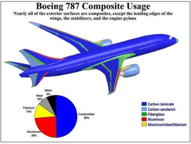
Hybrid material which also known as composite is widely used for multi- purpose in many of industries, especially in aerospace industries because this material offer high strength to weight ratio as well as the ability to create large integrated structure. For instance, the Boeing 787 Dreamliner (Figure 1.1) consists of 50 % composite material by weight, with much of that being carbon fibre laminates or sandwiches. CFRP consist
of the carbon fibres, which are effective in reducing the weight of structures and their
2
Figure 1.1: The material used in Boeing 787 Dreamliner
(Source: <http://webfiles.wichita.edu/cedbr/WIRED_comp_ov_5_14_08.pdf>09/10/13)
The mechanical strength of this material is affected by two major factors, which are the amount of distributions state of carbon and the bond of the binding material. Based on Oka et al. (2009), in a CFRP panel or the like, a peripheral portion becomes a region having an unstable quality because of the production process. Therefore, a method is
employed in which it is required to fabricate an extra peripheral portion in advance,
and after the resin is cured, the extra peripheral portion is cut off to get the product.
The trimming by using an end - mill cutter provides several advantages in which it
does not require the large- scale equipment and the existing processing machine still
can be used. Furthermore, the extra peripheral portion able to be removes without
preparing pilot holes. (Oka et al. 2009).
3 In consequence to the cost and time- consuming to conduct an experiment according to the design of experiment, prediction models is the best solution as it offer lots of advantages which allows a prevalent tool to analyse arbitrary geometries and loading conditions. Between the presences of numerical methods, FEA has been comprehensively used with success. Nevertheless, this analysis needs a large set in generation data in order to obtain authentic and accurate results.
The advantages of the prediction model in the machining will lead to optimize the performances of the cutting tool besides enhancing the quality of the workpieces. By developing the prediction model, the circumstances that occurred by cutting process able to discover and be able to analyse the phenomenon. Therefore, any of the factors that contributed to the performance and quality issues can be control.
1.2 Problem Statement
Trimming of CFRP is a common activity in the manufacturing of aircraft, marine and automotive application. Since a CFRP is a material for which burrs easily occur, even when the abrasion of the cutting edge is considered to be at a level that does not cause
a problem in metal machining, burrs occur in CFRP machining, and the cutting tool is
determined to have reached the end of its life at that moment. Therefore, even in an
end mill coated with a high-hardness coating, the end mill life is short in CFRP
machining (Oka et al. 2009).
1.2.1 Challenge in CFRP Machining
4 caused by the inhomogeneous nature of composite materials. Furthermore, CFRPs used for fuselages, wings and other parts of airplanes that are large in size in many cases, and fixing of such large workpieces easily becomes unstable because fixing points are limited during machining.
Figure 1.2: Defects on CFRP machined surface (Nor Khairusshima et al. 2013)
Therefore, it would be great if there is an alternative method to predict any complication in CFRP machining. Accurate prediction of the machining result will allow development of standard in processing CFRP and also able to optimize the parameter that controls the risk of consequences that can be intimidate of the material quality as well as the cutting tool performance.
To determine the relationship between CFRP and tool geometry, it is necessary to conduct an experiment, but there are lots constraints to conduct the actual experiment in terms of time and cost. CFRP is more costly due to their processing from primary material to hybrid material and by conducting the actual experiment; it would require lots quantity of CFRP as specimens and cutting tool as performance parameter.
5 simulate as well as studies on trimming of the composite structure not to mention CFRP.
1.2.2 Challenge in FEA modelling
Basically, the FEA modelling has become a daily engineering tool. But without proper fundamental knowledge and guidance will lead to poor experimental data correlate with FEA results. There are also have misconceptions about the solid structures represent best results. The challenge in build- up solid model more difficult in meshing because solid models often produces poor meshes with many degenerated elements. Besides that, automatically generated solid meshes need a larger number of elements to indicate the good model of the real stress distribution.
The other challenges in FEA modelling is the time trap, it occurred when the modelling process takes too long time in computing due the limitation of the computer hardware and it would cost a large investment in time. (Andruet et al. 2001). In reducing the cost of analysis, computational time is one of the important factors that should be reduce to allow running a relatively complex model along with modelling uncertainties regarding the boundary and loading conditions.
Modelling structures by using composite materials poses distinctive challenges, especially due to the need for concurrent design of both material and structure. Mostly, the difficulties in design and analysis of composite structures is about the anisotropic nature of the materials and the processing techniques used. The requirement in developing finite element analysis with composite materials are necessary to account for both of these aspects. Although, the widely of commercial FEA codes dominate the anisotropy effectively the application of the processing technique.
6
1.3 Research Objectives
The objectives of this project are:-
a) To develop a Finite Element Analysis (FEA) model for Carbon Fibre Reinforced Polymer (CFRP) trimming
b) To validate the Finite Element Analysis (FEA) model through the actual experiment.
1.4 Scope and Limitation
The scopes of this project are:-
a) The FEA modelling of CFRP trimming focus on cutter geometrical features b) Model of cutter assigns as un- deformable part
c) Apply the CFRP properties in Finite Element Analysis modelling
d) Experimental result focus on behaviour of machined surface and roughness.
1.5 Significant of the research
7
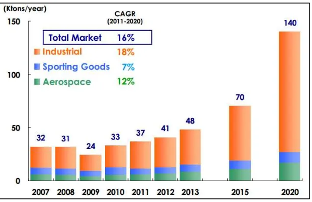
Figure 1.3: The global demand of CFRP start from 2007 until 2020 (Source: <http://www.toray.com/ir/pdf/lib/lib_a136.pdf> 09/10/13)
In addition, in terms of producing a CFRP panel, there are sections that called peripheral becomes an area that having unstable quality causes by the production process. Therefore, the current method to eliminate this problem is to produce the parts with an extra peripheral portion during the fabrication process. Then, after the resin cured, the extra peripheral portion is removed (cut off) to obtain a product. Therefore, this case was lead to requirement in trimming process of CFRP nowadays. The accurate prediction of the trimming results will increase the quality of the CFRP composite besides capable to optimize the parameter that controls the risk of consequences that can be intimidated of the material quality.
1.6 Structure of Dissertation
This report consists of five chapters which is covered on Projek Sarjana Muda I (PSM I) and Projek Sarjana Muda II (PSM II). The chapters of the reports are organised as follows: