REMOTELY OPERATED UNDERWATER VEHICLE (ROV)
RAYMOND TAN KEAN TATT
This report is submitted in partial fulfillment of the requirements for the award of Bachelor of Electronic Engineering (Computer Engineering) With Honors
Faculty of Electronic and Computer Engineering University Teknikal Malaysia Melaka
UNIVERSTI TEKNIKAL MALAYSIA MELAKA
FAKULTI KEJURUTERAAN ELEKTRONIK DAN KEJURUTERAAN KOMPUTER
BORANG PENGESAHAN STATUS LAPORAN
PROJEK SARJANA MUDA II
Tajuk Projek : ………
Sesi
Pengajian :
Saya ……….. (HURUF BESAR)
mengaku membenarkan Laporan Projek Sarjana Muda ini disimpan di Perpustakaan dengan syarat-syarat kegunaan seperti berikut:
1. Laporan adalah hakmilik Universiti Teknikal Malaysia Melaka.
2. Perpustakaan dibenarkan membuat salinan untuk tujuan pengajian sahaja.
3. Perpustakaan dibenarkan membuat salinan laporan ini sebagai bahan pertukaran antara institusi
pengajian tinggi.
4. Sila tandakan ( √ ) :
SULIT* *(Mengandungi maklumat yang berdarjah keselamatan atau kepentingan Malaysia seperti yang termaktub di dalam AKTA RAHSIA RASMI 1972)
TERHAD** **(Mengandungi maklumat terhad yang telah ditentukan oleh
organisasi/badan di mana penyelidikan dijalankan)
TIDAK TERHAD
Disahkan oleh:
__________________________ ___________________________________
(TANDATANGAN PENULIS) (COP DAN TANDATANGAN PENYELIA)
“I hereby declare that this report is the result of my own work except for quotes as cited in the references.”
Signature :………..
Author :……..………
“I hereby declare that I have read this report and in my opinion this report is sufficient in terms of the scope and quality for the award of bachelor of Electronic Engineering
(Computer Engineering) With Honors.”
Signature :………..……….
Supervisor’s Name :………..
v
ACKNOWLEDGEMENT
First I want to thank my supervisor Mr. David Yap Fook Weng. He had provided me guided for my final year project of University Technical Malaysia Melacca (UTeM). Mr. David is a responsible supervisor, he help me gather the component that I needed, and also pull me on the correct track when I off the track of my final year project. Besides that, he also encourage me while I facing problem in the progress of finishing my final year project, he had been a great supervisor and also a lecturer as well.
Secondly I want to thank my university (University Technical Malaysia Melacca). My University had provided me facilities and fulfills my needs on my final year project. All the equipment that I needed for my PLC based remotely operated underwater vehicle was well provided by my university. After that, I would like to thank my friends who give me moral support and encouragement. They had encourage continuously during progress of building PLC based remotely operated underwater vehicle.
vi
ABSTRACT
This report will state in detail the design of remotely operated underwater vehicle (ROV). Basically remotely operated underwater vehicle is control by a user on the boat and the ROV is used for research in undersea location where human cannot be able to reached. Remotely Operated Underwater Vehicle is designed base on low cost material and low electricity consumption. The application of the remotely operated underwater vehicle widely used in industry. Due to feature like camera, robotic arm and etc that can be add on, it very famous in underwater field. Beside this, the ROV is remotely control, so it can ensure the operator’s safety from the unknown condition under sea. Thrusters on the ROV enable it to move left, right, forward, backward, up and down. And the
vii
TABLE OF CONTENTS
CHAPTER TITLE PAGE
PROJECT TITLE i
BORANG PENGESAHAN STATUS LAPORAN PSM II ii STUDENT DECLARATION iii SUPERVISOR DECLERATION iv
ACKNOWLEDGEMENT v
ABSTRACT vi
TABLE OF CONTENTS vii
LIST OF TABLES x
LIST OF FIGURES xi
LIST OF ABBREVIATIONS xiii
LIST OF APPENDIX xiv
I INTRODUCTION 1.1 Introduction 1
1.2 Objective of Project 2
1.3 Problem Statement 2
1.4 Scope of Work 3
1.5 Explanation of Project Flow 3
1.6 Report Structure 4
viii
II LITERATURE REVIEW
2.1 Introduction 5
2.2 Background study 6
2.3 Programmable Logic Controller(PLC) 7 2.3.1 Advantage of Using PLC 7 2.3.2 PLC programming language 9 2.3.2.1 GX-Developer-FX 10
2.4 High Speed DC Motor 11
2.5 Propeller (Thruster) 13
2.6 Silicone (hot glue) 14
2.7 Glue Stick 16
2.8 Relay 16
2.8.1 Basic Operation and Designs 17
2.8.2 Type of Relay 17
2.8.3 H-Bridge (motor controller) 19
2.9 Polyvinyl Chloride (PVC) 20
2.10 Push Button 21
2.11 High Bright LED Underwater Light 22
2.11.1 High Brightness LED 23
2.12 Underwater Camera 24
III PROJECT METHODOLOGY
3.1 Introduction 26
3.2 Flow Chart of Project 27
3.3 System Block Diagram 29
3.4 Methodology 31
ix
IV RESULT AND DISCUSSION
4.1 Introduction 32
4.2 Hardware Design of ROV 32
4.2.1 Chassis of ROV 33
4.2.2 Thruster Unit 34
4.2.3 Motor Control 35
4.2.4 Motor Waterproofing 37
4.3 Ladder Diagram 38
4.4 Underwater Camera and Underwater Lighting System 40
4.5 Finalize ROV 41
4.6 Conclusion 42
V CONCLUSION & RECOMMENDATION
5.1 Recommendation 43
5.1.1 Robotic Arm 43
5.1.2 Floating System 44
5.1.3 RC controller 44
5.2 Conclusion 46
x
LIST OF TABLES
NO TITLE PAGE
1 Specification of Underwater Camera 24
xi
LIST OF FIGURES
NO TITLE PAGE
1 Mitsubishi FX1S PLC 7
2 High Speed Motor 11
3 Propeller Blade 13
4 Hot Glue Gun Loaded with Hot Glue Stick 14
5 Hot Glue Stick 15
6 Relay (24VDC) 16
7 The type of relay 17
8 A complete H-Bridge for motor control 19
9 Power on motor 20
10 PVC Pipe 21
11 Push Button 21
12 High Bright Led underwater torch 22
13 High Brightness LED overview 23
14 Underwater Camera 22
15 Flow Chart of Project Flow 27
16 System Block Diagram of ROV 29
17 Initial Chassis of ROV 33
18 After assembly with other component part 34
19 MY2 Omron Relay Connection Pin 35
20 Circuit Design of H-Bridge Using MY2 Omron Relay 36
xii
22 Motor seal by hot glue gun 37
23 Ladder Diagram of Thruster 38
24 Ladder diagram of bottom motor 39
25 ROV with installed underwater camera and underwater lighting system 40
26 Finalize ROV 41
27 ROV inside the water 41
xiii
LIST OF ABBREVIATIONS
ROV - Remotely Operated Vehicle
PVC - Polyvinyl Chloride
xiv
LIST OF APPENDIX
NO TITLE PAGE
1
CHAPTER I
INTRODUCTION
In this chapter, contains introduction, objective of the project, problem statement, and scopes of work, brief methodology, and report structure.
1.1Introduction
ROV has several sizes from small vehicles equipped with a tiny water proof camera which is used for observation, and mechanical tools like robotic arm for complex job requirement. Generally they are the freest flying in underwater. The ROV vehicle class includes the majority of low-cost vehicles, mostly are electrical controlled and operates above 984 feet (300 meters) water depth. The next step in advancing the technology is performed by commercial firms that saw the future in ROV support of offshore oil operations and the transition from military use to the commercial world was rather rapid. ROV had gained popularity with the military, oil and gas operations, and science markets due primarily to their quiet operation. In the case of ROV technology the answer is quite simple. There is no other practical, safe and economically feasible way to perform deep underwater intervention.
2
and expensive ownership. The idea of this ROV project is small, low cost, and underwater research vessel that capable of performing in deep depths of the ocean [1].
1.2Objective
There are three objectives for doing this project:
1. To design a robotic device which can travel through water, controlled by programmable logic circuit.
2. To create movement of the vehicle by controlling the polarity of motor. 3. To create low cost ROV compare to conventional ROV.
1.3Problem Statement
3
1.4Scope of Work
The scopes of work for this project are:
1. Using programmable logic control and interactive program GX-Developer FX to control the movement of ROV. Switches are defines as input of the programmable logic control, and the output of the programmable logic control are connect to relay to create movement of ROV.
2. PVC and silicon will be main material for waterproofing thruster of ROV, the connection between DC motor and cable must well water proofing, besides that the motor also must been water proofed, because water will cause short circuit.
1.5Explanation of Project Flow
4
1.6Report Structure
This report is to deliver the ideas generated, concepts applied, activities done, and finally the product of project itself. It consists of five chapters. Following is a chapter-by-chapter description of information in this report.
Chapter 1 gives reader a basic introduction to how the idea of this project generated. The chapter contains introduction, objective of the project, problem statement, scopes of work, brief methodology, and report structure.
Chapter 2 is a literature review on theoretical concepts applied in this project. The chapter concludes the background study of ROVs. Besides that, this chapter also explains how the ROVs work, what is PLC, what is waterproofing dc motor, and application of others component.
Chapter 3 introduces the methodology of the project. The chapter contains the flow chart which explains the overall method taken along the project carry out. Besides that, this chapter also introduces the construction of the project, which involves hardware development and software development. Basically, the hardware development for the project concludes with circuit design, prototype and body design. On the other side, the software development of project will discuss what programming is used, how to use the PLC, and how to implement it on this project.
Chapter 4 will be covered all the result from designing process. It will also include a discussion about the project. The chapter concludes with discussion on ROVs and control circuit for the system.
5
CHAPTER II
LITERATURE REVIEW
This chapter will describe details about the ROV, literature review on the parts and systems used in the project. It includes the explanation of individual component characteristic and also the advantages of using the particular component chosen for the project. The chapter will explain ROV, PLC, motor thrusters, battery supply, and serial communication method used in the ROV project.
2.1 Introduction
6
2.2 Background Study
Before any instruments had been made for working on water, underwater task has to be carried out by divers, this was a big problem because the natural conditions could be an restriction for any work for example in deep water is restricted the use of diver for high deep inspection was necessary to build some kind of instruments that can do the inspection work like maintenance and research work. They can be divided in three groups, machines that are controlled and manned by humans (like submarines), Remotely operated vehicles (ROV’s) and Autonomous vehicles (AV), first ones are generally used works of inspection and recognition of great areas or as warlike element, in other hand other ROV’s was developed unmanned because in some cases despite of being protected by the submarine, the conditions for the work wasn’t safe for humans like space, and duration of operation, for this kind of problem the ROV’s was used they are remotely operated far away for the place of the operation, maintaining safe of the operator for the risk conditions.
7
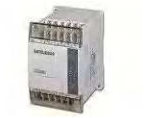
[image:21.612.214.457.102.301.2]2.3 Programmable Logic Control (PLC)
Figure 2.1: Mitsubishi FX1S PLC
A programmable logic controller (PLC) or programmable controller is a digital computer used for automation of electromechanical processes, such as control of machinery on factory assembly lines, amusement rides, or lighting fixtures. PLCs are used in many industries and machines. Unlike general-purpose computers, the PLC is designed for multiple inputs and output arrangements, extended temperature ranges, immunity to electrical noise, and resistance to vibration and impact. Programs to control machine operation are typically stored in battery-backed or non-volatile memory. A PLC is an example of a real time system since output results must be produced in response to input conditions within a bounded time, otherwise unintended operation will result.
2.3.1 Advantage of using PLC
8
low compared to the cost of a specific custom-built controller design. On the other hand, in the case of mass-produced goods, customized control systems are economic due to the lower cost of the components, which can be chosen instead of a smart solution, and where the non-recurring engineering charges are spread over thousands or millions of units [3].
A microcontroller-based design would be appropriate where hundreds or thousands of units will be produced and so the development cost can be spread over many sales, and where the end-user would not need to alter the command. Automotive applications are an example; millions of units are built each year, and very few end-users alter the programming of these controllers. However, some specialty vehicles such as transit busses economically use PLCs instead of custom-designed controls, because the volumes are low and the development cost would be uneconomic. Very complex process control, such as used in the chemical industry, may require algorithms and performance beyond the capability of even high-performance PLCs. Very high-speed or precision controls may also require customized solutions [4].
Programmable controllers are widely used in motion control, positioning control and torque control. Some manufacturers produce motion control units to be integrated with PLC so that G-code (CNC machine) can be used to instruct machine movements.
Processor plays a main role in most of the electronic circuit that manages the input and implements the output. It will take the signal input from switches, processes the signal and then to produce the logic output in order to control the rotation of the motor. In this project, the PLC CJ1G is chosen as the controlling unit. The PLC actually is a digital electronics system which uses a programmable memory for implementing specific functions like logic, sequencing, timing, counting and arithmetic to control through analog or digital input/output modules and other necessary types of machines or processes.
9
also allowing user to scale the system without having to change to another PLC family. The internal features built in this controller like normally open (NO), normally close (NC), timer, counter could make the ROV becomes one of the flexible underwater vehicles.
Other that, the CJ1G units CPUs range from very small CPUs for simple sequence control to powerful and fast models that offer flexible control circuit which can handle up to 16 I/O points for future adds-on purpose. This enables to modularize the machine into logical sections without changing PLC series. Then, CJ1G Power Supplies systems can operate on 24 V DC power supply, or on 100 - 240 V AC mains. Besides, the CJ1G digital I/O units serve as the PLC's interface to achieve fast, reliable sequence control. A full range of units, from high-speed DC inputs to relay outputs, let user adapt CJ1G to someone needs. Lastly, the CJ1G communication unit also provides both standardized open networks interfaces, and cost-efficient high-speed proprietary network links [5].
2.3.2 PLC programming language
10
to the PLC though a programming board which writes the program into a removable chip such as an EEPROM or EPROM [6].
There are three elements that commonly use in PLC ladder diagram:
The symbol of contact (normally close and normally open) is use for input. And the symbol of coil is use for output. While using this model of PLC, we need the software which use for this PLC – GX-developer-FX.