i
WIRELESS SERVER ROOM TEMPERATURE SYSTEM
MUHAMMAD ZAID BIN HASANI
WIRELESS SERVER ROOM TEMPERATURE SYSTEM
This Report Is Submitted In Partial Fulfillment of Requirements For The Bachelor Degree of Electronic Engineering (Wireless
Communication) With Honors
Fakulti Kejuruteraan Elektronik dan Kejuruteraan Komputer Universiti Teknikal Malaysia Melaka
“I hereby declare that this report is result of my own effort except for quotes as cited in the references.”
Signature : ……….
iii
“I hereby declare that I have read this report and in my opinion this report is sufficient in terms of the scope and quality for the award of Bachelor of
Electronic Engineering
(Wireless Communication) With Honors”
Signature : ……….
Supervisor’s Name : Cik Siti Aisah Binti Mat Junos@Yunus
v
ACKNOWLEDGEMENT
Alhamdullilah and praised be to Allah for his blessings and giving me the strength along the challenging journey to completing the project as well as this thesis writing, without it, I would not have been able to goes this far.
First of all, I would like to express my sincere gratitude to my supervisor, Siti Aisah Binti Mat Junos@Yunus for the continuous support for my PSM, for his patience, motivation, enthusiasm, and immense knowledge. His guidance helped me in all the time of research, developing and writing of this thesis.
ABSTRACT
vii
ABSTRAK
TABLE OF CONTENTS
CHAPTER TITLE PAGES
ACKNOWLEDGEMENT iv
ABSTRACT v
ABSTRAK vi
CONTENTS vii-ix
LIST OF FIGURE x-xi
LIST OF TABLE xii
1 INTRODUCTION
1.1 Background 1
1.2 Problem Statement 2
1.3 Objectives 2
1.4 Scope of project 3
1.5 Project Methodology 3
1.51 Flow chart 5
1.6 Report Structure 6
2 LITERATURE REVIEW
2.1 Sensor Review 7
2.1.1 Method of applying Sensor 8
2.1.3 Sensor Features 8
2.1.4 The advantages of Temperature 9 Sensor
2.2 PIC Microcontroller 10
2.2.1 PIC16F877A 11
2.2.2 Peripheral Features 12
2.2.3 Analog Features 13
ix
2.4 MAX 232 & RS 232 16
2.5 GSM Devices 17
2.6 Regulator LM7805 20
2.7 RS 232 Cables 21
2.8 Proteus 7 Software 22
2.9 CCS Compiler 23
3 PROJECT METHODOLOGY
3.1 Project Implementation 25
3.2 Project Flow Chart 29
3.3 Expected Result 31
4 RESULT AND DISCUSSION
4.1 Circuit Design 33
4.1.1 Power Supply 37
4.1.2 LM 35 48
4.1.3 LCD Display 40
4.1.4 PIC 16F877A 41
4.2 Software Design 41
4.2.1 C Programming Language 42
4.2.2 LM 35 Calculation 46
4.2.3 Hyperterminal 48
4.2.4 LCD Display Result 49
4.2.5 Overall View of Wireless Server 50 Room Temperature System
5 CONCLUSION AND SUGGESTION
5.1 Conclusion 52
5.2 Suggestion 53
xi
LIST OF FIGURES
NO TITLE PAGE
1.1 2.1 2.2 2.3 2.4 2.5 2.6 2.7 2.8 2.9 2.10 2.11 2.12 3.1 3.2 3.3
Flow Chart of the Project
Precision Centigrade Temperature Sensor (LM35) Full-Range Centigrade Temperature Sensor (LM35) PIC 16F877A
PIC 16F877A Bubble Diagram PIC 16F877A Memory Mapping LCD Display
MAX 232 and RS 232
Design Overview of GSM System GSM Device
LM 7805
LM 7805 Diagram RS 232 Cable
Flow Chart for Project Methodology Flow Chart of the Project
Block Diagram of Expected Result
5 8 9 10 13 14 15 16 17 17 20 20 21 26 29 31
4.1 Overall Block Diagram 34
4.2 Schematic Design using Proteus 7.8 35
4.3 Overall Schematic Circuit 36
4.4 PCB Layout 36
4.5 4.6 4.7 4.8 4.9
Power Supply Circuit LM 35
LCD Connection PIC 16F877A
LM 35 Calculation Coding
4.10 Function String on LCD Display 44
4.11 Warning Condition Coding 45
4.12 4.13 4.1.4 4.2.5
Schematic of LM 35 output Voltage Hyperterminal Output
LCD Display Result
Overall View of Wireless Server Room Temperature System
xiii
LIST OF TABLES
NO TITLE PAGE
2.1 2.2 3.1 4.1
PIC 16F877A Device Features
GSM Open AT Command and Description Pin Connection
Relationship between Temperature LM 35
Output Voltage and ADC Resolution (1°C-10 °C)
11 19 30 46
CHAPTER 1
INTRODUCTION
This chapter will explain about the background of project, objective of project, problem statement, scope of project and project methodology.
1.1 Background
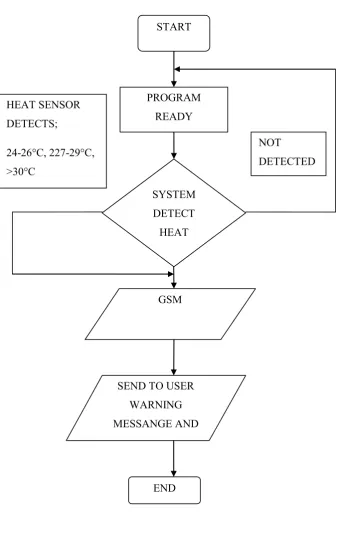
A server room needs continuous supervision to maintain their temperature. So to make sure the electronic component in the room is not damage, the server room, need to monitor by the technician 24 hours. From this state of problem the idea of Wireless Server Room Temperature System are developed. This project will help the technician to monitored the server room wirelessly by alert the technician that the temperature in the server room is not compatible with right temperature of server room and it need to be maintained. The right temperature of server room is 10°C - 16°C, if the temperatures are above that temperature it will alert the technician by sending message to the technician and also display it’s to the control room wirelessly through this system. There are 3 type of alert temperature that will send there are: (24-26°C early stage), (27-29°C middle stage) and (>30°C final stage).In the server room, there are 3 different temperatures that system are ready to set as a risk
2
1.2 Problem Statement
Server room requires constant monitoring to enable the cooling system running smoothly. The technician always have a problem in maintaining server temperature in idle temperature, they are also required a lot of time monitoring while they have other work to do. Normally the technician need to standby in server room to troubleshoot the problem that cause from server room overheating. The technician also have a problem to detect the heat in early stage that maybe cause from slightly malfunction of air conditioner or maybe the direct heat from outside temperature. All this problem will cause the early stage of server room overheating and bring damage to the component in server room.
1.3 Objective
The objectives of the project are:
To build the system that can reduce the damage of the component in the server room from the cause of overheating. The damage or the heat can be detected early from the setting of heat sensor in the system that installed in the server room.
To monitor in 3 stages of heat detection level 24-26°C early stage, 27-29°C middle stage, >30°C final stage. All this level can cause the damage for component in the server room.
1.4 Scope of Project
Project scope is listed as follow:
Study the principle and application of the project
Investigate the problem cause from server room overheating
Identify the component that related to the system like heat sensor circuit, PIC, Relay circuit, GSM, LCD Display
Construct the flow of the project progress and set the limitation of the project
Basically, this project is divided into two main parts:
Hardware design: The hardware for system is consist 3 heat sensor that detected 3 different temperature in the server room, it connected to relay circuit that triggered to PIC (microcontroller) to allow the message that can be sent to LCD Display. In The same time it also sent the message to Hand phone through GSM ( Global system for Mobile Telecommunication).
Software design: This system need to be programmed to be activated. To
make the heat sensor can be detected and triggered to PIC 16F877A programmed it on MP lab software.
1.5 Project Methodology
Figure 1.1 : Flow Chart of the Project SYSTEM
DETECT HEAT
GSM
SEND TO USER WARNING MESSANGE AND
LCD DISPLAY
NOT
DETECTED HEAT SENSOR
DETECTS;
24-26°C, 227-29°C, >30°C
START
END PROGRAM
6
1.6 Report Structure
This report represented by 5 chapters. The following paragraph below is the structure of developing Wireless Server Room Temperature System report:
Chapter 1: This chapter discusses about the brief overview about the project likes project background, problem statement, objective, scope of project and project methodology.
Chapter 2: This chapter discusses about all the information that have in this project. This chapter includes more about literature review about the hardware and software for developing this project.
Chapter 3: This chapter discusses more about the methodology, the implementation of the project and the expected result of Wireless Server Room Temperature System, it’s also include the explanation about all the flow of the project.
Chapter 4: This chapter discusses about the result and analysis of the development of this project, it’s also include the discussion of the project.
CHAPTER 2
LITERATURE REVIEW
This chapter presents the details about literature review of Wireless Server Room Temperature Sensor. Its consist the review of Precision Centigrade Temperature Sensor(LM 35), PIC Microcontroller, LCD display, MAX 232 and GSM device related with this project.
2.1 Sensor Review
To make the objectives of this project successful, some step must be used as a starting step. First step should be taken is doing a research on sensor that suitable in this project and select the sensor for Temperature Sensor.
Precision Centigrade Temperature Sensor (LM 35).
The LM35 is shown in figure 2.1 is precision integrated- circuit temperature sensor. The output voltage is linearly proportional to the Celsius temperature. The LM35 thus has an advantage over linear temperature sensors calibrated in Kelvin, as the user is not required to subtract a large
constant voltage from its output to obtain convenient Centigrade scaling. The LM35 does not require any external calibration or trimming to provide typical accuracies of ±1⁄4°C
8 linear output, and precise inherent calibration make interfacing to readout or control circuitry especially easy. It can be used with single power supplies, or with plus and minus supplies. As it draws only 60 μA from its supply, it has very low self-heating, less than 0.1°C in still air. The LM35 is rated to operate over a −55° to +150°C temperature range, while the LM35C is rated for a −40° to +110°C range (−10°with improved accuracy).
Figure 2.1 : Precision Centigrade Temperature Sensor (LM 35).
2.1.2 Methods of applying sensor
As shown in figure 2.2, LM35 can be applied easily in the same way as other integrated-circuit temperature sensors. It can be glued or cemented to a surface and its temperature will be within about 0.01°C of the surface temperature. This presumes that the ambient air temperature is almost the same as the surface temperature; if the air temperature were much higher or lower than the surface temperature, the actual temperature of the LM35 die would be at an intermediate temperature between the surface temperature and the air temperature.
2.1.3 Sensor Features
Calibrated directly in ° Celsius (Centigrade) Linear + 10.0 mV/°C scale factor
Low cost due to wafer-level trimming Operates from 4 to 30 volts
Less than 60 μA current drain Low self-heating, 0.08°C in still air Nonlinearity only ±1⁄4°C typical
Low impedance output, 0.1 W for 1 mA load
Figure 2.2: Full – Range centigrade Temperature Sensor (LM 35)
2.1.4 The Advantage of Temperature Sensor
Low cost and power usage, good stability, resolution and speed. Easy to integrate with PIC16F877A
Solid-state units have virtually unlimited, maintenance-free lifespan 0.5°C accuracy guarantee able (at +25°C)