PC BASED EXPERIMENT ON MS150 MODULAR SERVO SYSTEM
MOHD. HAMZI BIN ZAKARIA B010510066
PC BASED EXPERIMENT ON MS150 MODULAR SERVO SYSTEM
MOHD. HAMZI BIN ZAKARIA
This report is submitted in partial fulfillment of the requirements for the Bachelor of Electrical Engineering (Control, Instrumentation and Automation)
FACULTY OF ELECTRICAL ENGINEERING UNIVERSITI TEKNIKAL MALAYSIA MELAKA
“I hereby declared that I have read through this report and found that it has comply the partial fulfillment for awarding the degree of Bachelor of Electrical Engineering (Control, Instrumentation, & Automation)”
Signature : ………
“I hereby declared that this report is a result of my own work except for the excerpts that have been cited clearly in the references.”
Signature : ………
iii
To my beloved parents
Mr.Zakaria Mohd Noor & Mrs. Fadmah Abd. Majid
And
ACKNOWLEDGEMENT
v
ABSTRACT
ABSTRAK
Mesin Servo digunakan secara meluas di industri masa kini dan kebanyakan sistem kawalan yang di aplikasikan adalah melalui kawalan daripada komputer. Komputer dan instrument selalunya mudah dan biasa dihubungkaitkan, sama ada melalui modul antara muka. Pelajar kejuruteraan di dalam pengkhususan kawalan seharusnya mengenal dengan lebih mendalam mengenai sistem servo ini. Dalam usaha untuk mendalami ilmu ini, pembelajaran melalui amali adalah sangat digalakkan. Salah satu alat yang digunakan dalam amali ini ialah MS150 Servo System tetapi pembelajaran manual menyebabkan pembelajaran kurang efektif
vii
TABLE OF CONTENTS
CHAPTER SUBJECT PAGE
DECLARATION i
DEDICATION iii
ACKNOWLEDGEMENT iv
ABSTRACT v
ABSTRAK vi
TABLE OF CONTENTS vii
LIST OF TABLES x
LIST OF FIGURES xi
LIST OF APPENDICES xiii
1 INTRODUCTION 1
1.1 Project Background 1
1.2 Project Objectives 1
1.3 Project Scopes 2
1.4 Problem Statement 2
1.5 Project Layout 2
2 LITERATURE REVIEW 4
2.1 Introduction 4
2.2 Control System 4
2.3 Process 6
2.4 System Tools 7
2.4.1 Computer 8
2.4.2 Interfacing Module 12 2.4.2.1 Parallel Interface 13 2.4.2.2 Serial Interface 13 2.4.3 Feedback MS150 Modular Servo
System 13
3 METHODOLOGY 15
3.1 Overview 15
3.2 MS150 Modular Servo System 16 3.2.1 Power Supply PS150E 18 3.2.2 DC Motor DCM 150F 19 3.2.3 Servo Amplifier SA150D 19 3.2.4 Reduction Gear Tacho Unit
GT150X 20
3.2.5 Attenuator Unit AU150B 20 3.2.6 Op Amp Unit OA150A 21 3.2.7 Experiment setup 22
3.3 Interfacing Module 24
3.3.1 Advantech PCI-1711 Data
Acquisition Card 25
3.3.2 Product specifications 25 3.3.2.1 Analog Input 25 3.3.2.2 Analog output 26 3.3.2.3 Digital Inputs 26 3.3.2.3 Digital Outputs 26 3.3.2.4 Pacer/Counter 27
3.3.2.5 General 27
3.3.3 Analog Input Connections 27 3.3.3.1 Single-ended Channel
Connections 28
3.3.3.2 Analog Output
ix
3.3.4 Feedback 33-301 Analogue
Control Interface 30
3.4 Computer 31
3.4.1 Model Design 31 3.4.2 Feedback DAC Ch2 DA2 32
3.4.3 Slider Gain 34
3.4.4 Analog Input 35
3.4.6 To Workspace 37
3.4.7 Display 38
3.4.8 Model Setup 39
3.4.9 Model Execution 39 3.4.10 Data Storage 43
3.5 Project Flow 44
4 RESULTS AND DISCUSSION 46
4.1 Computer Control Experiment 46 4.2 Simple Speed Control System 46
4.3 Graph Plotting 48
4.4 Discussion 54
5 CONCLUSION AND RECOMMENDATION 56
5.1 Conclusion 56
5.2 Recommendation 56
REFERENCES 58
LIST OF TABLE
NO TITLE PAGE
4.1 Result of simple speed control for manual tuning 47 4.2 Result of simple speed control system for computer
xi
LIST OF FIGURES
NO TITLE PAGE
2.1 Closed-Loop Control System 6
2.2 The concept of a servo system 7
2.3 Basic component of servo systems 8 2.4 Overview of analog digital converter and digital analog
digital converter 8
2.5 Rapid prototyping process 10
2.6 Traditional versus rapid prototyping process 11 2.7 Real-Time Windows Target library 19
3.1 Methodology overview 15
3.2 Overview of the project 16
3.3 Block diagram of basic components of MS150
Modular Servo System 17
3.4 Electrical layout of servo motor 17
3.5 Power Supply PS150E 18
3.6 Servo Amplifier SA150D 19
3.7 Reduction Gear Tacho Unit GT150X 20
3.8 Attenuator Unit AU150B 21
3.9 Layout of Op. Amp. Unit OA150A 21
3.10 Connections for manual tuned environment 22
3.11 PC based connection setup 23
3.17 Connection between Computer and servo system 31 3.18 Simulink model for simple speed control 32
3.19 DAC Unit Parameters 33
3.20 Under mask of Feedback DAC block 33 3.21 Subsystem for scaling and safety block 34
3.22 Parameters of slider gain 34
3.23 Analog Input block with display 35
3.24 Parameters for analog input and DAQCard testing 36
3.25 Card testing 36
3.26 Test result shows the board available 36
3.27 To Workspace parameters 37
3.28 Display block parameters 39
3.29 Parameters for simulation time and solver option 39 3.30 Configuration to save data at workspace 40 3.31 Configuration for Real-Time Workshop 40
3.32 System target file browser 41
3.33 Building the model 42
3.34 Workspace 43
3.35 Axes editor 43
3.36 Flow project 44
3.37 Overall project flow chart 45
xiii
LIST OF APPENDICES
NO TITLE PAGE
A PCI-1711 Block Diagram 60
B C code for RTW 61
C Generated C code for model 62
D C code for data 68
CHAPTER 1
INTRODUCTION
1.1 Project Background
Control system is a system or a device or set of device to manage, conduct command, order and direct or regulate the behaviors of the other device or one system. With it we can control or change the speed of the motor to our own desired one.
So, this proposed project is about to develop a user interface of these controllers for controlling the speed of the motor which means user can control the servo system variable via Personal Computer (PC). The development of user interface will be implementing using Mathwork Matlab Simulink software. This produced system will incorporate interactive and graphical for convenience and user-friendly.
1.2 Project Objectives
The main objectives of this project are to execute laboratory exercises for DC servo system with aided control from Personal Computer (PC). Other purposes of this project are:
To improve the experiment studies on analog servo control system.
To avoid difficulties with analog implementation
2
1.3 Project Scope
This project may cover an experiment of servo control system, which is simple speed control system. It also may cover:
Using Matlab Simulink/ Real-Time Workshop to run the servo system in computer environment.
Develop user interface in computer environment.
Implement DAQCard Advantech PCI-1711 to interfacing servo system with computer.
Using Feedback MS150 Modular Servo System for project hardware
1.4 Problem Statement
The laboratory exercise usually tuned manually. Therefore, some problem might occur during laboratory session. Those problems are:
Less accurate in tuning the experiment equipment.
Difficult to test the designed digital servo control model.
Less accurate in data acquisition for analysis.
1.5 Report Outline
Layout of the thesis will tell the flow of the whole thesis and its contents. This could be the referring section for this project.
This chapter also includes the main objectives of the project and the scope of whole project.
Chapter 2 contains the theory of the whole project. It comprises the element that need to be covered in this project. The theories of the project are based from the references that will be guidance for the project.
Chapter 3 indicates the methodology to complete and success the project. Project methodology is about defining fundamental principles, rules and manners to complete the project. It is a way to use all available techniques, tools and approaches used to achieve predetermined objectives. It shows the flow of the project from the beginning and illustrates with the flow chart that review the important methods that should be considered by developers before a project is carried out. It is important for a developer to demonstrate an awareness of methodological tools available and the understanding that is suitable for the project.
Chapter 4 likewise point out the results and discussion of the project. The developed real-time data simulation system will be shown in the result part. For the discussion part, the system will be compare with manual tuning experiment to make sure it is in accurate condition.
CHAPTER 2
LITERATURE REVIEW
2.1 Introduction
Machine Servo is used extensively in industrial sector nowadays because of its advantages. It includes shorter positioning time, higher accuracy, better reliability, improved repeatability (consistency), coordinated movement and servo clamping [6],[11],13] For this case, servo control system is very important. As for the engineering student in control field, they should be familiar with this system and in order to achieve it, laboratory educational is needed. Instead of manual laboratory educational, discovery learning also can be applied by giving the freedom for student to choose their own procedures rather than just following the outlines [2],[6],[13]. Refer to [5], manual laboratory exercises can now be enhanced or upgraded to the automatically tuned with the aid from computer. With the technology that available nowadays, graphical user interface also can be developed along with the laboratory exercises as refer to[3],[5],[9],[12].
2.2 Control System
One type of control system is Open Loop control system. It also called linear control system or non-feedback control system. This type of system may compute its input into a system using only the value of set point from the input and its model of the system. A characteristic of the open-loop controller is that it does not use feedback to determine if its input has achieved the desired goal. This means that the system does not observe the output of the processes that it is controlling. Consequently, a true open-loop system can not engage in machine learning and also cannot correct any errors that it could make as refer to [5-6].
It also may not compensate for disturbances in the system. Open-loop control is useful for well-defined systems where the relationship between input and the resultant state can be modeled by a mathematical formula. For example determining the voltage to be fed to an electric motor that drives a constant load, in order to achieve a desired speed would be a good application of open-loop control. If the load were not predictable, on the other hand, the motor's speed might vary as a function of the load as well as of the voltage, and an open-loop controller would therefore not be sufficient to ensure repeatable control of the velocity. An open-loop controller is often used in simple processes because of its simplicity and low-cost, especially in systems where feedback is not critical. A typical example would be a conventional washing machine, for which the length of machine wash time is entirely dependent on the judgment and estimation of the human operator. Generally, to obtain a more accurate or more adaptive control, it is necessary to feed the output of the system back to the inputs of the controller. This type of system is called a closed-loop system [5-6].
6
Figure 2.1: Closed-Loop Control System from [5]
In this configuration a feedback component is applied together with the input R. The difference between the input and feedback signals is applied to the controller. In responding to this difference, the controller acts on the process forcing C to change in the direction that will reduce the difference between the input signal and the feedback component. This, in turn, will reduce the input to the process and result in a smaller change in C. This chain of events continues until a time is reached when C approximately equals R. A closed-loop system is able to regulate itself in the presence of disturbance or variations in its own characteristics. In this respect, a closed-loop system has a distinct advantage over an open-loop system as refer to [5-6].
2.3 Process
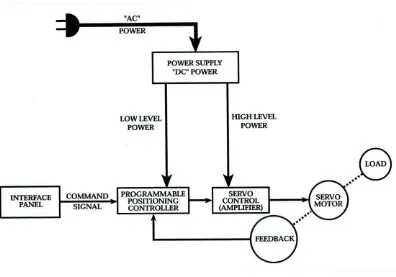
Figure 2.2: The concept of a servo system
After the load begins to move, there is other device that also moves to provide a feedback signal to the controller. This device can be a tachometer, resolver or encoder as refer from[7]. In this servo system, process variable such as position and speed of the motor is control. The system can be fully control by computer if the computer control the process variable [11],[5-6],[7].Refer to [11], in order to complete the project, 3 element is needed to develop. Those 3 elements were computer (software), interfacing and hardware.
2.4 System Tools
8
Figure 2.3: Basic component of servo systems.
2.4.1 Computer
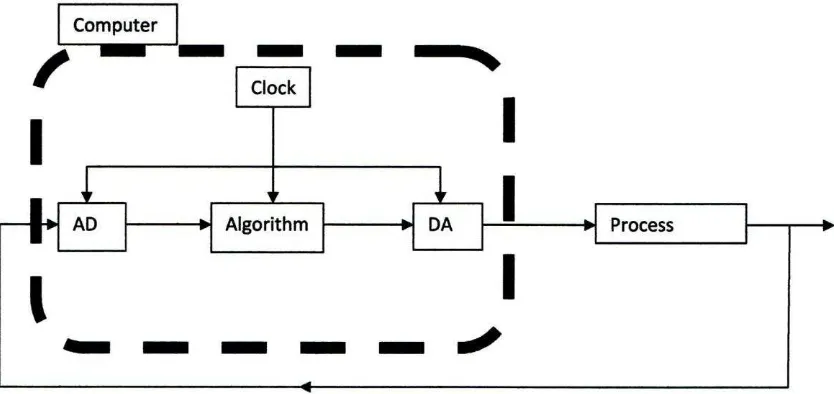
Personal Computer, (PC) will be the controller that send signal to the servo amplifier before it level up the signal to the proper level that move the DC motor. PC input is digital while servo system input is analog, so the translator is needed. In this case, interfacing will be the translator from [1],[4-5],[8],[11]. The figure 2.3 refers to [5] show the overview of analog to digital converter and digital to analog converter.
[image:23.595.101.518.444.641.2]2.4.1.1 Matlab Simulink
Simulink is a software package that can be model, simulate, and analyze systems whose outputs change over time. These systems are always referred to as dynamic systems. Simulink can also be used to explore the behavior of a wide range of real-world dynamic systems, including electrical circuits, shock absorbers, braking systems, and many other electrical, mechanical, and thermodynamic systems. There are two step processes in simulating dynamic systems with Simulink. First, a user creates a block diagram, using the Simulink model editor, which graphically depicts time-dependent mathematical relationships among the system's inputs, states, and outputs. The user then commands Simulink to simulate the system represented by the model from a specified start time to a specified stop time. In order to control the project in real time, real-time workshop is needed [16].
2.4.1.2 Real-Time Workshop
![Figure 2.1: Closed-Loop Control System from [5]](https://thumb-ap.123doks.com/thumbv2/123dok/633079.76718/21.595.131.475.87.179/figure-closed-loop-control-system-from.webp)