Journal of Instrument
journal homepage: http://icoci.org/joiImplementation of Active Force Control to Reduce Vibration Displacement in Active
Mass Damper during Seismic Activity
M.A.Salim1, A.Noordin2, M.H.C.Aman3
(1,3 Faculty of Mechanical Engineering, Universiti Teknikal Malaysia Melaka, Hang Tuah Jaya, 76100, Durian Tunggal, Melaka, Malaysia)
(2 Faculty of Electrical Engineering, Universiti Teknikal Malaysia Melaka, Hang Tuah Jaya, 76100, Durian Tunggal, Melaka, Malaysia)
RECEIVED DATE (2011-6-11)
Abstract: High structure in this world are using damper as a vibration controller device. The vibration control in a building is very important due to the public safety. In this study, Active Mass Damper (AMD) is used as a building’s structure and tested using Active Force Control (AFC) during the seismic activity. By using a software, two dimensional mathematical models and transfer function, stability of AMD and stability of AMD with AFC was identified, respectively. From the analysis, without AFC, the vibration displacement of AMD is slightly proportional due to amplitude and time. With AFC, the overshoot of the AMD system was reduced to 0% and the relationship between vibration displacement, amplitude and time was nonlinear for each others. For a conclusion, the AFC has a potential to reduce the relationship between vibration, amplitude and time and can gives AMD system more stable.
Key words: Active mass damper, active force control, seismic, vibration displacement.
1.0 Introduction
For the reason subjected to series of the structural vibration when considered the location exposing the structure such as high building and long bridge to the earthquake or strong windfall, advanced technology in engineering and improvement in material quality becomes important and relevant to study the structures span. Vibration can be pleasant and useful in massaging and therapeutic application but at the same time it can be unpleasant and harmful because it can lead to catastrophic failures of components and materials. Unwanted vibration yield issues of comfortable, damage to the structures, and reduction of equipment performance and machinery noise level. Electronics components used in automobile or planes, machine and even building structure could fail because of the vibration. Structural control is a different field of study. These studies look promising to attain the reducing of vibration if loadings such as an earthquake or strong winds happen. The important way to reduce this vibration is by installing a mechanical system to the structure. The structural control is based on passive, active, semi active and hybrid controllers depending on their consumption energy which offering more option to mitigate the losses and damage caused by the natural hazards.
Any structure that is built must be designed with certain forces in consideration. The forces buildings must withstand are live and dead loads. Dead loads is referred to the loads that are permanent and do not move. Live loads refer to the loads that can be moved. Other forces that play a big role in consider overall strengths of a building are wind, snow, earthquake, and waves. Many buildings have been built as passive structures. Passive structures use mass and solidity to resist forces. As passive structure, it cannot adapt to the changes of environment. Year-by-year, structural safety is of great importance. Thus, the structural control takes on a new technology that permits the design of lighter structures with control. The new concepts of structural protection are damping, passive control and active control. Active control acts as a means of extra protection for structures that are at the high risk for seismic activity. Passive control devices used to protect some existing structures or buildings in are as of low seismic activity. Overall idea of active control is a revolutionary one. It has the capability to elevate structural concepts from static and passive level to a dynamic and adaptable level. Active control may not be the most cost effective measure in protecting buildings those are in areas of low risk for earthquakes. Comparing with the passive control, active control is capable in adapting to the surrounding changes. This mean they are capable to use the force by both adding and dissipating energy in the structure.
2.0 Active Force Control
Active Force Control (AFC) is a very robust control scheme and first proposed by Hewit et al in late 1970s [1]. The AFC method is a technique that relies on the appropriate estimation of the inertial or mass parameters of the dynamic system and the measurements of the acceleration and force signals induced by the system if practical implementation is ever considered [2]. For theoretical simulation, it is normal that perfect modeling of the sensors is assumed and that noises in the sensors are totally neglected. In AFC, it is shown that the system subjected to a number of disturbances remains stable and robust via compensating action of the control strategy [3]. The system mainly uses the estimated or the measured values of a number of parameters to accomplis h the compensation of all disturbances that are prevalent in any dynamical system [4]. This system is a closed loop that can automatically adjust to reduce
force. The essence of the AFC strategy is to obtain the estimated disturbances force, F*via the measurement of mass
acceleration, a and actuator force,
a
F together with an appropriate estimation of the estimated mass, M * as
described in the equation 1:
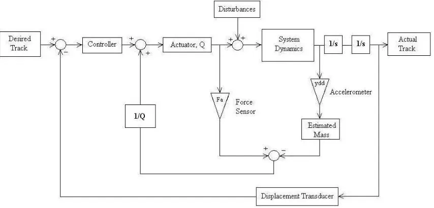
The equation is very simple and is expected to be computationally light, in fact a very attractive option for real time or on-line implementation [1]. The AFC device relies on a stand-alone controller that takes the user requested force and automatically delivers that force to the part with high degree of accuracy. The stand -alone controller allowed additional processing features. In the simplest application, the force remains constant throughout the process; a user can input the value directly into the active controller and operate completely separately. The schematic diagram of AFC is shown in Figure 1 below.
Fig. 1 Schematic diagram for Active Force Control
3.0 Active Mass Damper
An Active Mass Damper (AMD) is also known as Tuned Mass Damper (TMD) or harmonic absorber, is a device mounted in structures to prevent discomfort, damage or outright structural failure caused by vibration. These devices are frequently used in power transmission, automobiles and buildings. In AMD phase, the active mass moves for two degree of freedom vibration structure. When the actuator is stopped, the active mass combines with the passive mass and both are regarded as dynamic absorber. This AMD is a mechanical device that suppresses the vibrations of a structural system using reaction forces generated by moving the auxiliary mass with an actuator connected between the structure and the auxiliary mass. Many applications of AMD to real buildings and civil structures have been reported [5]. The AMD is a passive control device that can be attached to the building in order to reduce its response and vibration. The device consists three parts and there are:
ii. Spring. It is constant and chosen to tune AMD to several modes of the building controller. iii. Viscous damper. It is damping coefficient obtain by iteration.
In order to achieve the most efficient energy absorbing capacity, the damper tunes its natural frequency with the natural frequency of the structure but has a phase shift.
4.0 Mathematical Modeling of Active Mass Damper
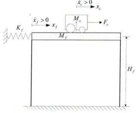
The working principle of AMD is using two degree of freedom vibration structures. When the actuator is stopped, the active mass combines with the passive mass and both are regarded as dynamic absorber [6] -[7]. AMD schematic diagram is shown in Figure 2 below:
Fig 2 Schematic diagram for Active Mass Damper
The Lagrange’s technique is used to derive the mathematical model of two degree of freedom of AMD. By
using this technique, the potential and kinetic energies of the system can be derived. The total potential ener gy, in a system is the amount of the energy of the system. This energy can make a vertical displacement from normality (gravitational potential energy) or by a spring related sort of displacement (elastic potential energy). According to this situation, there have no gravitational potential energy with both of AMD cart and the structure is assumed to stay at a constant elevation. The top floor of the AMD is modeled as a linear spring mass system. The total energy of AMD is only due to the elastic potential energy [8]. The basic equation of force that applied to the AMD is,
The inertial rotation of the motor’s armature is neglected, therefore the dynamic model of this motor will be more accurate. Then, the inertial force of the cart will be applied to the Newton’s second law of motion with the
D’Alembert’s principle equation. The equation can be expressed by,
For the motor pinion, the armature inertial force into the motor rotation and it can act to the armature inertial torque. The equation can be expressed by,
Then, using the Newton’s second law, the equation of motion of the motor shaft can be expressed by,
The mechanical configuration of the cart’s rack opinion system can be defined at the following relationship,
Substitute the equation 5 and 6 into equation 4. The new equation of armature inertial force is,
Then, substitute equation 2 and 7 into equation 8. By rearranging, the new equation can be expressed by,
From equation 9, it is expressed by second order differential equation in the cart position. Using the Laplace Transform technique and rearranging for open loop transfer function, the new equation of AMD can be expressed by,
5.0 Analytical Analysis
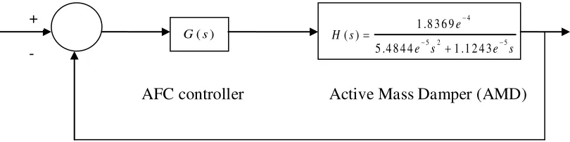
The block diagram of AFC and AMD is shown in Figure 3 below:
Fig 3 Block diagram of Active Force Controller and Active Mass Damper
The transfer function of AMD is:
The final closed loop transfer function is:
6.0 Result and Discussion
This sub-chapter discusses the stability analysis for AMD without any controller involved and for the second analysis is AMD with AFC. In this stability analysis, four stability diagrams were used and they are:
i. Step response diagram analysis ii. Bode diagram analysis
iii. Nyquist diagram analysis iv. Root locus diagram analysis
(b) Bode diagram for AMD
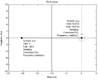
(d) Root locus diagram for AMD
Fig 4 Stability analysis for AMD without any controller
Figure 4 (a) shows the step response diagram for AMD. According to this graph, the linear line is represented the behavior of AMD itself. It is means that, if the AMD in working condition, the vibration displacement is slightly proportional to the amplitude and time. Based on the vibration condition, if vibration displacement proportional to amplitude and time, it has a big potential the building structural to collapse when the vibration displacement increase based on time. Controller is needed to reduce this and finally avoid the phenomenon from happens. Figure 4 (b) shows bode diagram analysis of AMD. Based on this diagram, the value of peak gain is approximately 232 dB. The frequency of this AMD is approximately . The natural frequency of AMD system cannot be detected because the analysis in the experimental is only used a plant and not involved any disturbances to influent the system. From Figure 4 (c), the margin point 1 is infinity. It means the value cannot be read by the system and based on this value, the AMD system has a critical condition to control the vibration displacement when the seismic problem happen. The closed loop for AMD system is under stabilizing. The phase margin of this system is approximatel y to 89.5 deg and the delay margin is 9.57 deg, respectively. The frequency of this system is 0.163 rad/sec. According to Figure 4 (d), it represents the root locus diagram for AMD system. For the first impression, the diagram shows the unstable condition because they have a linear line between point 1 and point 2. Theoretically, if the system is in a stable condition, point 1 must be nearly to point 2.
(c) Nyquist diagram for AMD with AFC
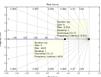
(d) Root locus diagram for AMD with AFC
Fig 5 Stability analysis for AMD with AFC
Figure 5 (a), shows the step response diagram for AMD with AFC. According to this figure, the overshoot of the system is approximately to 0% and this is for sure that the condition of the system is obeying the regulation of the necessary to reduce and avoid the vibration displacement happen. Besides, the rise time of the system is 20 sec, peak
amplitude is and with rise time is 6.85 sec. Figure 5 (b) describes the natural frequency of the system. The frequency of the system is approximately to where this frequency is referred as a natural frequency of the system. Then, the peak gain of this system is 74.7 dB. Figure 5 (c) shows two points which is position in the circle. This means that the system is stable and the poles express the performance of the controller. In point 1, the phase margin is 90 deg and frequency is . The peak gain is 74.7 dB and the frequency in point 2 is . For the root locus diagram, the overshoot is 0% and it shows that the system is in the stable condition. Besides, it also has same values for the damping point and gain point. The differences are only at the value of the pole point and frequency. At point 1 has pole point -0.214 and point 2 has pole -46.8. For frequency, point 1 is 0.214 rad/sec while point 2 has 46.8 rad/sec.
7.0 Conclusion
Active Mass Damper (AMD) is used as a building to simulate the vibration situation. By adding a controller device, the vibrations occur is reduced but the most practical controller is giving more value to the engineering field. Throughout the experiments and simulation using physical testing and software, Active Force Control (AFC) has a highly potential to reduce the vibration displacement to the building structural during the seismic activity.
8.0 Acknowledgement
The author would like to thank to Fakulti Kejuruteraan Mekanikal, Universiti Teknikal Malaysia Melaka.
References
[1] M. Mohammad, M. Mailah, A.H. Muhammad, Vibration control of mechanical suspension system using active force control, Universiti Teknologi Malaysia.
[2] S.B. Hussein, H. Jamaluddin, M. Mailah, An intelligent method to estimate the inertia matrix of a robot arm for active force control using on-line neural network training scheme, Jurnal Mekanikal, 1999, 2(8): 38-53, 1992.
[3] M.Z.M. Zain, Active force control with input shaping technique for a suspension system, Jurnal Mekanikal, 2008, Universiti Teknologi Malaysia, No 27, 91-104.
[4] M.Mailah, An active control method to reduce the effect of negative damping in disk brake system, Conference on Innovatrive Technologies in Intelligent Systems and Industrial Applications, 2009, Monash University.
[5] Y. Kazunobo, M. Itaru, Vibration control for a structural system using AMD with restricted stroke, American Control Conference, 2009, 1237-1243.
[6] K.Villarreal, Effects of MR damper placement on structure vibration parameter, Proceeding of the 2005 IEEE Conference Control Engineer. 12 – 44, 2005.
[7] T.Kobori, N.Koshika, K.Yamada, Y.Ikelda, Seismic response controlled structure with active mass driver system. Proceeding of the 1991 IEEE Verification Earthquake and Structural Engineering Dynamic, Japan, 65
– 86, 1991.