ISSN: 1693-6930
accredited by DGHE (DIKTI), Decree No: 51/Dikti/Kep/2010 645
Genetic Algorithm of Sliding Mode Control Design for
Manipulator Robot
Ahmad Riyad Firdaus1, Arief Syaichu Rahman2 1
Department of Electrical Engineering Politeknik Negeri Batam
Parkway Batam Center, Batam Kepulauan Riau 29461, Indonesia, Ph./Fax:0778-469856/0778-463620 2
Electrical Engineering STEI – Institut Teknologi Bandung, Jl.Ganesha 10, Bandung, Indonesia e-mail: [email protected], [email protected]
Abstrak
Model dinamika robot manipulator direpresentasikan dengan sistem persamaan matematika yang sifatnya nonlinear. Selain dari itu, manipulator memiliki parameter-parameter inersia yang bergantung pada beban robot dan sifat fisis lainnya yang nilainya sulit diketahui secara pasti. Pengendali Modus Luncur (PML) memiliki kekokohan yang baik dalam megendalikan sistem linear maupun nonlinear. Kinerja pengendali ini sangat ditentukan oleh pemilihan parameter pengendali dari penguat pensaklaran (k) dan permukaan luncur (s).Sangat sulit untuk memperoleh parameter kendali yang optimal. Pada makalah ini, algoritma genetika dibuat untuk mengoptimisasi pemilihan parameter pengendali dalam melacak nilai-nilai parameter pengendali yang optimal agar menghasilkan kinerja PML yang diinginkan. Pengujian dilakukan dengan memberikan posisi referensi untuk joint 1 dan joint 2 dari robot manipulator sebesar 45O dengan indicator kinerja pengendali adalah settling time < 2 detik, dan toleransi kesalahan penjejakan adalah 1%. Hasil simulasi memperlihatkan kinerja yang lebih baik dari PML dengan algoritma genetika dengan kecilnya tanggapan waktu sebesar 1,03 detik untuk joint 1 dan 1,05 detik untuk joint 2 serta kesalahan penjejakan dari status keluaran sebesar 0,15% untuk joint 1 dan 0,04% untuk joint 2 .
Kata Kunci: pengendalii modus luncur, robot manipulator, sistem nonlinear, kesalahan penjejakan, algoritma genetika.
Abstract
The dynamical model of manipulator robot is represented by equations systems which are nonlinear and strongly coupled. Furthermore, the inertial parameters of manipulator depend on the payload which is often unknown and variable. The sliding mode controller (SMC) provides an effective and robust means of controlling nonlinear plants. The performance of SMC depends on control parameter selection of gain switching (k) and sliding surface constant (s). It is very difficult to obtain the optimal control parameters. In this paper, a control parameter selection algorithm is proposed by genetic algorithm to select the gain switching (k) and sliding surface constant parameter (s) so that the controlled system can achieve a good overall performance in the sliding mode controller design. Testing is done by giving a reference position for joint 1 and joint 2 of the robot manipulator of 45O (degree) with the controller performance indicator is settling time <2 seconds, and the tracking error tolerance is 1%. Simulation results demonstrate better performance of the PML with a genetic algorithm with a small response time by 1.03 seconds to 1.05 seconds joint 1 and 2 as well as for tracking error of the output state by 0.0015 degree for joint 1 and 0.0004 degree for joint 2.
.
Keywords: sliding mode controller (SMC), manipulator robot, nonlinear system, tracking error, genetic algorithm.
1. Introduction
Manipulator robot is a robot which has a function to do some working like pick and place [1]. The dynamical model of manipulator robot is represented by equations systems which are nonlinear and strongly coupled. Furthermore, the inertial parameters of manipulator depend on the payload which is often unknown and variable [2-4]. So, to avoid these problems we studied SMC which is well suited to manipulator robot application. The SMC provides an effective and robust means of controlling nonlinear plants.
time [5], [6]. This control system is robust because provides a method to design a system in such a way that the controlled system should be insensitive to parameter variations and external disturbances [7]. In the application, this does not require an accurate model of the robot (plant): it is only necessary to know the boundaries of the parameter variations and load disturbances.
In this research, SMC is applied to PUMA 260 manipulator 2-DOF (Degree Of Freedom). The goals of controller are to control the position and speed of robot arm with small time response and steady state error. At the previous research, backstepping adaptive control has been applied with the same plant [8]. The simulation result, for the reference position 45O the system need 2 second to achieve the goal position with 0.5 degree steady state error and still have overshoot. With SMC method is expected can improve the time response, minimizing steady state error and eliminate overshoot that happened when using backstepping adaptive controller. Factors that influence the performance of SMC is the control parameters of switching gain (k) and the sliding surface (s). It is very difficult to obtain the optimal control parameters in order to produce a good control performance [9]. Genetic algorithms are applied to optimize the parameters of the search that is expected to produce good control performance [10].
2. The Proposed Method 2.1 Sliding Mode Controller
A general type of the motion equation is represented in the space state [11] by equation (1).
) ( ) , ( ) , ( )
(t f x t B x t u t
x& = + (1)
wherex(t)∈ℜnis status vector, u(t)∈ℜm is the control input, and the functions f(x, t) and B(x, t) are nonlinear and not known exactly.
The control input is represented by equation (2).
(2)
,...,
1
0
)
(
)
,
(
0
)
(
)
,
(
)
,
(
i
i
i
m
x
t
x
u
x
t
x
u
t
x
u
i i
i
=
<
>
=
+−σ
σ
with σi(x)=0 is i th component of the m sliding surface m R x = σ∈
σ( ) 0, .
Generally, there are two step in SMC design, that are:
a. Sliding surface design
Sliding surface can be represented by the equation (3).
)
(
)
(
x
=
Sx
t
σ
(3)With S is the matrix has dimension m x n and constant elements. The values matrix can not be determined with any cause stability of the system on sliding surface will determined by these constant.
For the tracking task to be achievable using a finite control u, the initial desired state xd(0) must be such that xd(0) = x(0). The tracking error of state x can be defined by the
equation (4).
e = x – xd = [
) 1 (
...
e
n−e
e
&
]T (4)where e is tracking error vector. Furthermore, lets define a time varying surface σ(t) in the state
space
ℜ
nby scalar equation σ(x;t)=0, where,σ(x;t)= e e e
dt
d n
n
&
+ =
+ −
− 1 1
λ
where λ is strictly positive constant, and n is the system order.
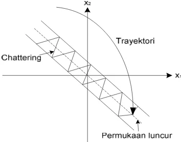
b. SMC design
In this design, control law u(t) made by using lyapunov stability condition σTσ& <0. In general, the control law can be considered separately by the two control terms, that are ueq and
un, so that the system control law obtained by summed both two control signal, such as seen at
the following equation (6).
)
(t ueq un kx
u = + =− (6)
ueq is an aquivalen control signal that will transfer the state anywhere to hit the sliding surface,
and the un is the natural control signal that will keep the system staying on sliding surface, as
shown in Figure 1.
Figure 1. Phase plane
By substituting the equation (1) and (6), the close loop dynamic is obtained as writen in the following equation (7).
) )(
, ( ) , ( )
(t f xt B x t ueq un
x& = + + (7)
When state trajectory hit the sliding surface and sliding mode is occurred, this condition satisfied
0
)
,
(
x
t
=
σ
&
and σ(x,t)=0 at every t≥to for some to, so the equivalent control can be representedby the following equation (8).
) , ( )) , (
(SB x t 1Sf xt
ueq =− − (8)
To keep state trajecory from sliding surface, there is a condition to fullfil on the sliding surface
0 * )
( = <
= sBun un
Tσ σ σ
σ & . The control signal can be represented by the following equation (9).
) ( jika ) ( 1 )) , (
(SB xt sign sB invertible
k n
u =− − σ (9)
2.2 Genetic Algorithm
Genetic algorithms are optimization methods inspired by the principles of genetics and natural selection proposed by Darwin (Darwin's Theory of Evolution). In the application of genetic algorithms, the solution variables are coded into a string that represents the gene sequences, which are characteristic of the problem solution.
A. generate the initial population,
Initial population is generated randomly in order to obtain the initial solution. Population itself consists of a chromosome that represents the desired solution.
B. evaluation of solutions,
This process will evaluate each population by calculating the value of fitness function until criteria are met. Generation that has the best fitness value is expected the desired optimal solution.
C. forming a new generation.
In shaping a new generation used of the three operators, that are reproduction/selection operator, crossover, and mutation.
3. Research Method
There are several step to design Genetic Algorithm of SMC for Manipulator Robot, such as: manipulator modeling, SMC design for manipulator, and optimizing SMC by genetic algoritm.
3.1 Model of manipulator.
There are two steps to model a manipulator robot, which are: kinematics modeling, and dynamics modeling. Robot kinematics is analytical study of robot arm movement to the coordinate framework of silent/moving reference regardless of force causing the movement. Kinematics model represent the relation of end effectors in three dimension space with variable of joint in the joint space. Robot dynamics is mathematical formulation which depicts dynamic behavior of manipulator considered force causing the movement.
By using lagrange-euler method, is obtained inverse dynamic equations for each joints expressing joint torque to accelerations with DC motors actuator [8] by following equations (10-11).
(10) cos
sin 3
2 3
3 cos
1 1
1 2 1 2 2 2 2 2 1 1 1
1 2 2 2 2 2 2 1
1 L
m L L L L L
m L
n F l
m n n
J l
m n
θ θ
θ θ θ θ
θ
τ = + && − & & + &
(11) cos
2 1 cos
sin 3
1 3
3
2 2 2 2 2 2
2 2
1 2 2 2 2 2 2 2 2
2 2 2 2 2 2
2 L L
m L L L L
m
gl m n n
F l
m n n
J l m n
θ
θ
θ
θ
θ
θ
τ
= + && + & + & +where τ1 and τ2 are the torque of joint 1 and joint 2, m1 and m2 are mass for each link, l1 and l2
are length of each lengths, Jm1 and Jm2 are inertias of motors, Fm1 and Fm2 are viscous
coefficients of motors, θL1 and θL2 are the joints angle of movement, and n1 and n2 are gear ratio
for each joint.
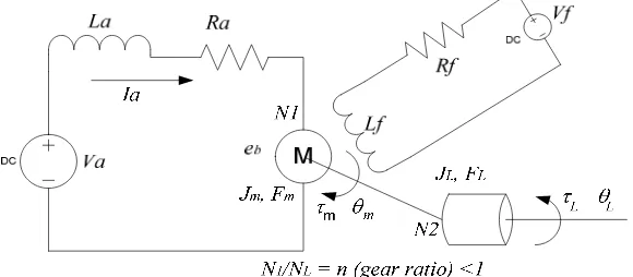
The type DC motor is armature-controlled. The output of DC motor is controlled by armature voltage, whereas field current kept in constant. Figure 2 is the schematic of DC motor.
Since the torque developed at the motor shaft increas linearly with the armature current, independent of speed and angular position, then the torque can be written by the following equation (12). a a
i
K
=
τ
(12)Whereas, armature voltage
b a a a a a e dt di L R i
V = + + (13)
where
n K
eb b m m L
θ
θ
θ
== & dan
thus,
−
=
L a b a a anR
K
R
V
K
θ
τ
&
(14)By substituting the equation (10), (11) and (14), is obtained:
1 1 1 1
1 H BVa
D
θ
&& = + (15)2 2 2 2 2
2 L H G BVa
D
θ
&& = + + (16)where,
(
)
1 1 1 2 1 2 2 2 2 2 1 1 1 1 1 1 1 1 1 1 1 2 2 2 2 2 2 1 1 cos sin 3 2 3 3 cos a a L L L L L m a b a m L R K B l m n n F R n K K H n J l m n D = + + − = + = θ θ θ θ θ θ & & &(
)
2 2 2 2 2 2 2 2 2 1 2 2 2 2 2 2 2 2 2 2 2 2 2 2 2 2 2 2 2 2 2 2 cos 2 1 cos sin 3 1 3 3 a a L L L L L m a b a m R K B gl m n G l m n n F R n K K H n J l m n D = − = − + − = + = θ θ θ θθ& &
If select the statex1=θL1;x2=θ&L1;x3=θL2;x4=θ&L2, the control input are u1 =Va1;u2 =Va2 and desired output arey1=
θ
L1;y2=θ
L2, thus, the nonlinear state equation of manipulator2-DOF can be written by the following equation (17).
(
)
+ + = − − − − 2 1 2 1 2 1 1 1 2 2 1 2 4 1 1 1 2 4 3 2 1 0 0 0 0 0 0 u u B D B D G H D x H D x x x x x & & & & (17)x
y
=
0
1
0
0
0
0
0
1
(18)3.2 SMC for Manipulator
The operation target are to make output (x1 and x3) following reference input (x1r and
− −
− −
=
0 0
4 3 3
2 1 1
x x x
x x x
e
r r
where e is tracking error of state. The transien response of the system is based on selecting switching variables. The following equation (19) and (20) are the sliding surface for joint 1 (
x
1)and joint 2 (
x
3)of manipulator robot.(
r)
(
x xr)
dt d x x
S1 1 1 1 1
1= − + −
σ
r x S x x
S1 1 2 1 1
1= + −
σ (19)
(
r)
(
x xr)
dt d x x
S2 3 3 3 3
2= − + −
σ
r x S x x
S2 3 4 2 3
2 = + −
σ (20)
Thus, the matrix of sliding surface can be obtaoned by the following equation (21).
0 , 1
0 0
0 0 1
2 1 3 2
1 1
2
1 >
− − +
= S S
x S
x S x S S
r r
σ (21)
From equation (21), the selection of S relate to system dynamics to influence system time response. Chosen correct S, hence poles at closed loop system will be able to be accommodated with a purpose of controlling.
3.3 Optimizing SMC parameters by Genetic Algorithm.
In this section, a genetic based SMC method is proposed so that the parameters of SMC (k and S) are self-generated by means of Genetic Algorithm based on the direction of a proposed fitness function [7]. In order to select the set of control parameters R=(k and S) by using genetic algorithm, first, we select R as a parameter set and code it as a finite-length string, then choose a fitness function so that genetic algortithm can be used to search for a better solution in the parameter space. If we define a function, the search direction of genetic algorithm will depend on the requirement of fitness function. So it is a key role on the defined fitness function so that the controlled system can achieve a desired performance. In this paper, we want to find the gain parameters and sliding surface constants of the SMC to reduce the time response of x1 and x3 (Tr) and the steady state error and the amplitude of control input of
the controlled system, so we propose the following objective function [13]:
( )
( )
(
)
2max 3 2 2 2
1T c e c U
c
F= r + + (22)
Where c1, c2, c3 are multiplying constants that can be adjusted according to designer’s
specification or the system requirement. The fitness function can be defined by the following equaition (23).
1
1
+
=
F
f
(23)( )
{ }
f RMAX (23)
where R is a string which represents a point located in the search space. Hence, three basic genetic operators can be applied to select the parameters {k, S1, S2}to maximize the
performance index in the parameter space. If the final string is obtained, it can be selected as the SMC parameters that a high performance can be achieved.
4. Result and Discussion
In this simulation, will be showed and compare the performance of SMC optimized by genetic algorithm, trial and error method, the performance of controller with disturbance, and backstepping adaptive control performance . The simulation start with zero initial state, and step input function. In order to be able to compare the performance proportionally, reference position of
x
1 andx
3 are 45O with performance indicator selected is settling time (ts)<2s (secon) with 1 %tolerance.
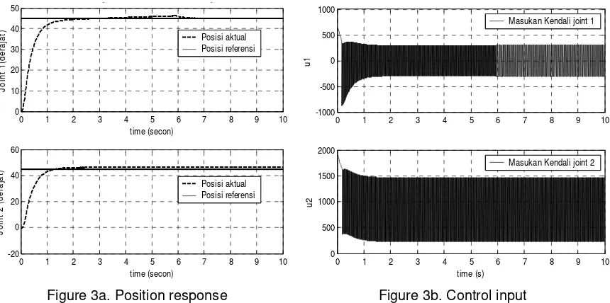
4.1 Trial and Error Method
In this method, the selection of gain switching (k) and sliding surface contants is done by trial and error. The selected of these parameters are: k=15, S1=3 dan S2=3. The system
response is shown in Figure 3.
Figure 3a. Position response Figure 3b. Control input
Figure 3. The system response when the parameters by trial and error
From simulation obtined the datas as following: ts1=2.1s ; ts2=1.24s; ess (
x
1)= 0.008014 dan ess(
x
3)= 0.000820.4.2 Genetic Algorithm Methode.
This methode is used to obtain the best combination of gain switching k and sliding surface constants S terbaik. The tunning is done autoamticly. Genetic algortithm parameters are crossover probability=0.8; mutation probability=0.05; length of chromosomes bit =12 x 3 bits; max generation=100; population=30; range of search space P: k= 0 – 15; S1 and S2 =1 – 10.
Objective function constants are c1=7.10
5
; c2=7.10
5
; dan c3=1.
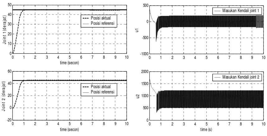
From optimization result, is obtained SMC parameters data as following: k = 8.699145; S1 = 6.316484; S2=6.624176; ts1=1.03s ; ts2=1.05s; ess (
x
1) =0.001506 and ess (x
3)= 0.000422.The system response is shown as following Figure 4.
0 1 2 3 4 5 6 7 8 9 10
0 10 20 30 40 50
J
o
in
t
1
(d
e
ra
ja
t)
Sf=[9.969231 1 0 0;0 0 9.514286 1]
time (secon)
Posisi aktual Posisi referensi
0 1 2 3 4 5 6 7 8 9 10
-20 0 20 40 60
time (secon)
J
o
in
t
2
(
d
e
ra
ja
t)
Posisi aktual Posisi referensi
0 1 2 3 4 5 6 7 8 9 10
-1000 -500 0 500 1000
u
1
Masukan Kendali joint 1
0 1 2 3 4 5 6 7 8 9 10
0 500 1000 1500 2000
time (s)
u
2
Figure 4a. Position response Figure 4b. Control Input
Figure 4c. Fitness function Graph
Figure 4. The system response when the parameters by genetic algorithm
From Figure 3 and Figure 4 can be showed that the settling time of optimized system are smaller then conventional methode. This performance can be showed from ts1=2.1s ;
ts2=1.24s to be ts1=1.03s ; ts2=1.05s, ess (
x
1) = 0.008014 ; ess (x
3) = 0.000820 ; to be ess (x
1)=0.001506 and ess (
x
3)=0.000422.4.3 Disturbance to System
In this simulation will be showed the performance of SMC, if there are any disturbance (unknown and variable parameters) at the system. If we select the change of robot parameters: mass (m) 0.5 kg, inertia (Jm) 5.10
-6
and viscous coefitien (Fm) of actuators. The obtained system
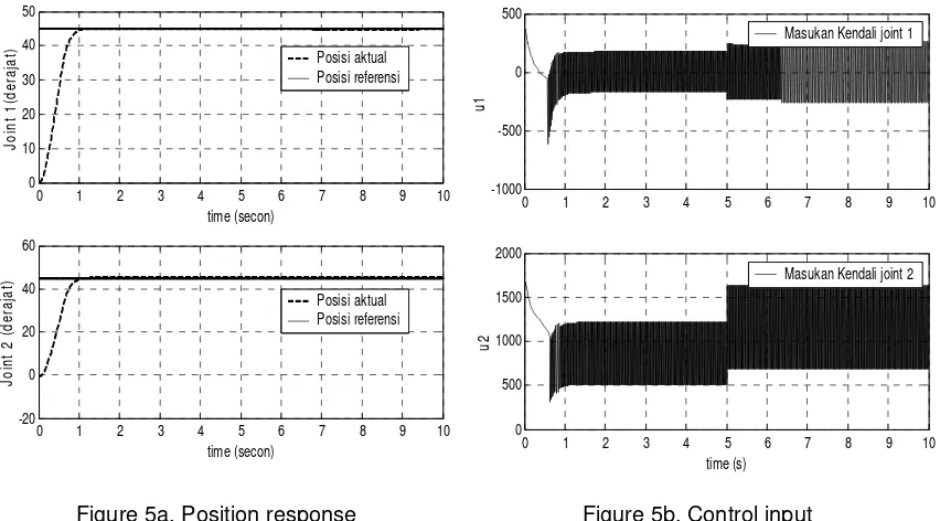
response can be shown at following Figure 5. From simulation, can be obtained the data of system response, that are: ts1=1.03s ; ts2=1.05s; ess (x1) =0.001506 dan ess (x3)=0.000422.
Comparing the simulation results of the two methods from Figure 3 and Figure 4, we find that the overall performance of the proposed method genetic algorithm SMC is better than trial and error method SMC. That is the objective that the gain switching and sliding surface constants parameters can be automatically selected, so that the controlled system has a better performance of small time response and small steady state error are satisfied. From Figure 4c,
0 1 2 3 4 5 6 7 8 9 10
0 10 20 30 40 50
J
o
in
t
1
(d
e
ra
ja
t)
time (secon)
Posisi aktual Posisi referensi
0 1 2 3 4 5 6 7 8 9 10
-20 0 20 40 60
time (secon)
J
o
in
t
2
(
d
e
ra
ja
t)
Posisi aktual Posisi referensi
0 1 2 3 4 5 6 7 8 9 10
-1000 -500 0 500
u
1
Masukan Kendali joint 1
0 1 2 3 4 5 6 7 8 9 10
0 500 1000 1500 2000
time (s)
u
2
Masukan Kendali joint 2
0 20 40 60 80 100 120
2.19 2.2 2.21 2.22 2.23 2.24 2.25 2.26x 10
shows that the value of fitness function converge at 8th iteration. That is mean, there is no difficult to search appropriate parameters for SMC.
Figure 5a. Position response Figure 5b. Control input
Figure 5. Efect of the changing of system variable (parameters) to the performance of controller
The changing of system variable (parameters) does not influent the performance of controller (Figure 5). That is shown by the same of time response and steady state error of the system. The change of control input value is to keep the system on the steady state condition. If comparing with the previous research, backstepping adaptive control has been applied with the same plant [8], the simulation result for the reference position 45O the system need 2 second to achieve the goal position with 0.5 degree steady state error and still have overshoot. The result of proposed method is better then backstepping adaptive control as previous research. Another previous research, Design of Adaptive Sliding Mode Controller for Robotic Manipulators Tracking Control [9] shown that performance is still affected by external disturbance.
5. Conclusion
In this paper, the problem about the improvement of SMC design is investigated. It is desirable to have the fast reaching output state response to achieve reference and small steady state error of the system. The changing of robot parameters do not influence the performance of SMC. The main objective is to propose an effective method to choose an appropriate parameter set by using genetic algorithm to reduce the time response and attenuate the steady state error so that a high overall performance of small time response and small steady state error can be achieved.
The advantage of the genetic algorithm is that they don't need extra professional knowledge or mathematics analysis. During the execution of the genetic algorithm, only the fitness function of the strings is evaluated. The performance surface doesn't need to be differentiated with respect to the change of control parameters and no derivatives, gradient calculations or other environment knowledge is necessary by genetic algorithm. From the results, we find that the control parameters can be easily and efficiently selected fiom the proposed method and the selected control parameters can provide the controlled system with a high global performance where the time response is small and the steady state error is small
.
0 1 2 3 4 5 6 7 8 9 10
0 10 20 30 40 50
J
o
in
t
1
(d
e
ra
ja
t)
time (secon)
Posisi aktual Posisi referensi
0 1 2 3 4 5 6 7 8 9 10
-20 0 20 40 60
time (secon)
J
o
in
t
2
(
d
e
ra
ja
t)
Posisi aktual Posisi referensi
0 1 2 3 4 5 6 7 8 9 10
-1000 -500 0 500
u
1
Masukan Kendali joint 1
0 1 2 3 4 5 6 7 8 9 10
0 500 1000 1500 2000
time (s)
u
2
References
[1] Endra Pitowarno, ROBOTIKA Desain, Kontrol dan Kecerdasan Buatan, Penerbit ANDI Yogyakarta, 2006.
[2] M. Belhocine, M. Hamerlain, and K. Bouyoucef, “Robot Control Using a sliding mode”
[3] M.R. Soltanpour, M.M. Fateh, “Sliding Mode Robust Control of Robot Manipilator in Task Space by Support of Feedback Linearization and Backstepping Control”, World Applied Sciences Journal 6(1):70-76, 2009.
[4] S.E. Shafiei, S. Sepasi, “Incorporating Sliding Mode and Fuzzy Controller with Bounded Torques for Set-Point Tracking of Robot Manipulator” Electronics and Electrical Engineering – Kaunas: Technologija, Iran, 2010. – No. 8(104). – P.3.8
[5] Raymon A. DeCarlo, Stanislaw H.Zak, Gregory P.Matthews, “Variable Structure Control of Nonlinear Multivariable System: A Tutorial”, Proceeding of The IEEE, vol. 76, no. 3, March 1988, pp.212-224. [6] Slotine, J-J E., Weiping Li, Apllied Nonlinear Control, Prentice-Hall International, Inc. 1991, 276-284. [7] Ching-Chang Wong, Shih-Yu Chang, “Parameter Selection in the Sliding Mode Control Design Using
Genetic Algorithms”, Tamakang Journal of Science and Engineering, vol. 1, no. 2. 1998, pp. 115-122. [8] Patria Rahman Hakim,”Perancangan dan Simulasi Sistem Kendali Meriam Hidrolik dengan Metode
Kendali Backstepping Adaptif”, Tesis Program Studi Teknik Elektro ITB, 2008, hal 24, 40, 50
[9] T.C.Kuo, Y.J.Huang, B.W.Hong, “Design of Adaptive Sliding Mode Controller for Robotic Manipulators Tracking Control”, World Academy of Science, Engineering and Technology 77, 2011. [10] K.S.Fu, R.C. Gonzales, C.S.G. Lee, ROBOTICS Control, Sensing, Vission, and Intelligence,
McGraw-Hill International Editions, 1987
[11] Riko Nofendra, “Pengendali Modus Luncur Untuk Motor Listrik”, Tesis Program Studi Teknik Elektro ITB, 2006, hal. 22-30
[12] Robert E. King, Computational Intelligence in Control Engineering, Marcel Dekker, Inc.,1999. [13] Ahmad R. Firdaus, Arief S. Rohman, Hilwadi Hindersah,””Perancangan Pengendali Modus Luncur