DESIGN, ANALYSIS AND FABRICATION OF REGENERATIVE AUTOMOTIVE SUSPENSION SYSTEM TEST RIG MODULE
RAZLAN BIN RAZALI
SUPERVISOR DECLARATION
“I hereby declare that I have read this thesis and in my opinion, this report is sufficient in terms of scope and quality for the award of the degree of
Bachelor of Mechanical Engineering (Automotive)”
Signature : ...
Supervisor : DR MOHD AZMAN BIN ABDULLAH
DESIGN, ANALYSIS AND FABRICATION OF REGENERATIVE AUTOMOTIVE SUSPENSION SYSTEM TEST RIG MODULE
RAZLAN BIN RAZALI
This report is submitted in partial fulfillment of the requirements for the award Bachelor of Mechanical Engineering (Automotive)
Faculty of Mechanical Engineering Universiti Teknikal Malaysia Melaka
DECLARATION
“I hereby declare that the work in this thesis is my own except for summaries and quotations which have been duly acknowledged.”
Signature : ...
Author : RAZLAN BIN RAZALI
iii
ACKNOWLEDGEMENT
v
ABSTRACT
ABSTRAK
vii
TABLE OF CONTENTS
CHAPTER TITLE PAGES
DECLARATION ii
DEDICATION iii
ACKNOWLEDGEMENT iv
ABSTRACT v
ABSTRAK vi
TABLE OF CONTENT vii
LIST OF TABLE x
LIST OF FIGURE xi
LIST OF SYMBOLS xiv
LIST OF ABBREVIATION xv
LIST OF APPENDICES xvi
CHAPTER 1 INTRODUCTION 1
1.0 Introduction 1
1.1 Problem Statement 2
1.3 Objective 2
1.4 Scope of Project 3
1.6 Summary 3
CHAPTER 2 LITERATURE REVIEW 4
2.1 Vehicle Suspension System 4
2.1.1 Background of suspension 4
2.1.2 Purpose of the Suspension System 6
2.1.3 Component of Suspension System 6
2.1.4 Spring 7
2.1.5 Shock Absorber 9
2.1.6 Types of Suspension System 11
2.2 Magnet 15
2.3 Electromagnet 16
2.3.1 Introduction of Faraday’s Law 17
2.3.2 Faraday’s Law Concept 17
2.4 Resistivity of Conductor 18
2.5 Past Research on Energy
Regenerative System 19
2.6 Previous Research Result 21
2.7 Test Rig 22
2.8 Stress Analysis 22
2.9 CATIA Software 23
CHAPTER 3 METHODOLOGY 24
3.1 Background Study 24
3.2 Flowchart 25
3.3 Gantt Chart 27
3.4 CATIA Drawing 29
3.4.1 Sketch 29
3.4.2 Dimension 30
3.4.3 Installation of EReSS to Perodua Myvi
Suspension System 31
3.4.4 Part by Part of the Design 32
3.4.5 Spring 32
ix
(EReSS) 34
3.4.7 Shock Absorber 39
3.4.8 Initial Design 40
3.4.9 Final Design 41
3.5 Perodua Myvi Specification 43
3.6 Fabrication of Test Rig Module 44
CHAPTER 4 FABRICATION AND ANALYSIS 45
4.1 Introduction 45
4.2 Fabrication 45
4.2.1 Material 46
4.2.2 Shearing Machine 46
4.2.3 Bending Machine 47
4.2.4 Welding Machine 48
4.2.5 The Drill Machine 50
4.2.6 Grinder Machine 52
4.2.7 The Assemble of Product 53
4.3 Analysis 55
4.3.1 Calculation Value of C1 and C2 55
4.3.2 Calculation of Force 57
4.3.3 Deformation Analysis and Safety Factor 58
CHAPTER 5 DISCUSSION 61
CHAPTER 6 CONCLUSION 64
6.1 Conclusion 64
6.2 Recommendation 65
REFERENCES 66
LIST OF TABLE
NO TITLE PAGES
3.1 Gantt Chart for The First Semester 27
3.2 Gantt Chart for The Second Semester 28
3.3 Perodua Myvi Specification 43
4.1 Mass of Vehicle Without Driver 56
xi
LIST OF FIGURE
NO TITLE PAGES
2.1 The Basic Component of The Suspension System 5
2.2 Coil Spring Made From Tapered Rod 7
2.3 The Leaf Spring 8
2.4 The Torsion Bar 8
2.5 The Air Spring 9
2.6 Construction of a Simple Shock Absorber 9
2.7 Shock Absorber Mounted and Assembly With The Coil
Spring 10
2.8 Double Wishbone Suspensions 11
2.9 McPherson Strut Suspensions 12
2.10 Bags and Strut 13
2.11 Multi-Link Suspensions 14
2.12 Trailing-Arm Suspensions 15
2.13 Electromagnetic Induction 16
2.14 The Resistivity of Material 18
2.15 The Regenerative Brakes 21
2.16 Diameter coil = 0.8 mm at 40 Hz 21
2.17 Diameter coil = 0.5 mm at 40 Hz 21
2.18 Test Rig 22
3.1 CATIA Software V5R20 24
NO TITLE PAGES
3.3 The Dimension of Each Component in The Perodua
Myvi Car 29
3.4 Taking The Dimension 30
3.5 Jack Up The Perodua Myvi Car and Remove The Tire 30
3.6 Installation of EReSS at Suspension System of Perodua
Myvi
31
3.7 Exploded View 32
3.8 Assembly of Spring 32
3.9 Top Cap 33
3.10 Bottom Cap 33
3.11 Spring 33
3.12 Assembly of EReSS 34
3.13 Exploded View of EReSS 34
3.14 Housing 35
3.15 Magnet Configuration 35
3.16 Aluminium Main Shaft 36
3.17 Aluminium Barer Shaft 36
3.18 Magnet Holder 37
3.19 Top Cap 37
3.20 Bottom Cap 37
3.21 Inner Block 38
3.22 Holder Bracket 38
3.23 Shock Absorber 39
3.24 Assembly of Initial Design 40
3.25 Exploded View of Initial Design 41
3.26 Assembly of Last Design 42
3.27 Exploded View of Last Design 42
xiii
NO TITLE PAGES
3.29 Mild Steel 46
4.1 Mild Steel (Thickness 3mm) 46
4.2 (a) The Front Side Shearing Machine (b) The Back Side
Shearing Machine 46
4.3 Cutting The Mild Steel 47
4.4 The Steering if Bending Machine 47
4.5 (a) Bending Process (b) The Work Piece of Bottom
Mounting
48
4.6 The MIG Welding Machine 48
4.7 (a) Spring Weld Top and Bottom Cape (b) Cape is
Being Weld With Screw
49
4.8 Top Mounting Being Weld 49
4.9 Drill Machine and its Component 50
4.10 (a) Smaller Screw Being Drill (b) Larger Screw 50
4.11 Oil to Cold The Area and Extend Lifespan of Screw 51
4.12 Spring Attach to The Bottom Mounting 51
4.13 (a) The Grinder Machine (b) The Cylinder Rod is Being
Cut to Four Similar 52
4.14 (a) Bottom Mounting Assemble (b) Top and Bottom
Mounting 53
4.15 Complete Assemble of The Test Rig Module 54
4.16 (a) The Side from EReSS (b) The Side From Spring 54
4.17 Perodua Myvi Wheelbase 54
4.18 Data of Vehicle Mass With Drive 56
4.19 Lower Mounting (Displacement) 59
4.20 Lower Mounting (Von Misses) 59
4.21 Upper Mounting (Displacement) 60
LIST OF SYMBOLS
N = Newton
˚C = Degree Celsius
Hz = Frequency
V = Volt
% = Percentage
kg = Kilogram
mm = Millimeters
W = Weight
xv
LIST OF ABBREVIATION
EReSS = Energy Regenerative Suspension System
KERS = Kinetic Energy Recovery System
CATIA = Computer Aided Three-dimensional Interactive Application
EMF = Electromotive Force
DASYLab = Data Acquisition System Laboratory
MATLab = Matrix Laboratory
LIST OF APPENDICES
NO. TITLE PAGE
A Different Angle View of Complete Fabrication 70
1
CHAPTER 1
INTRODUCTION
1.0 INTRODUCTION
Today’s world is full of technologies and commitment, the need of a person to be at one place after another is a must. Therefore, a vehicle is a necessity for a person to do such thing.
Harvesting energy from vibration is one of the most promising technologies. There were researches to figure out where energy is being wasted in a moving vehicle. Some hybrid cars are already recovering the energy from breaking. Therefore, the research interest had been searching elsewhere and narrowed down on the suspension system. There were different types of car models, which had been attached sensors to the suspension, to determine energy potential and then recorded the sensor data from laptop computers. The test revealed that a significant amount of energy was being wasted in conventional suspension system (Zuo & Tang, 2013).
system. This project is to make sure that the test rig module will be used in the future to compare the data and increase the voltage by research.
1.1 PROBLEM STATEMENT
There was waste energy produced in suspension system while travelling. This project is to ensure that the waste energy produced from the vibration of suspension system can be used for something useful. This Energy Regenerative Suspension System (EReSS) can change the waste energy which is kinetic energy created by the movement of suspension due to the condition of the road surface to electrical energy using the theory of electromagnet. This voltage from EReSS can be used to recharge the battery pack. Unfortunately the voltage produced is in small scale. Therefore, mathematical models should be developed in order to make a simulation so that the parameter can be changed and run easily. Therefore, this test rig module is essential to be used in comparison to EReSS being put at Perodua Myvi to find ways to increase the voltage in the future.
1.2 OBJECTIVE
The objective of this project are to design, to do analyze and fabricate the EReSS test rig module.
1.3 SCOPE OF PROJECT
3
1.4 SUMMARY
CHAPTER 2
LITERATURE REVIEW
2.0 INTRODUCTION
The regenerative energy from the suspension is the method that uses energy resulting from the vibration of the vehicle while driving on the road. The kinetic energy can be converted into useful energy such as electrical energy. The electrical energy can be used to recharge the battery pack. The product that's being designed in this project is called as “Energy Regenerative Suspension System” (EReSS). Based on the study that had been done, the profile of the road surface in this country, mostly bumpy, uneven and cracked which will help to produce vibration in the vehicle while driving. Therefore, the energy regenerative vibration can be produced. This chapter will discuss the vehicle suspension system, the use of magnets and coil to produce regenerative energy.
2.1 VEHICLE SUSPENSION SYSTEM
2.1.1 Background of Suspension
5
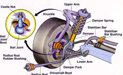
[image:23.595.113.542.278.541.2]The thing needed to give good ride comfort is soft suspension, while insensitivity to applied loads requires stiff suspension. So to give good handling of the vehicle, it would require a suspension setting between the soft and stiff. The ability to store energy via a spring and to dissipate the energy via a damper is called as passive suspension system. While the ability to store, dissipate and to introduce energy to the system is called as an active suspension system. So due to the demands of consumers, the suspension need to be designed as something of a compromise. Usually, it will be determined by the type of use for which the vehicle was designed. Figure 2.1 shows an example of the vehicle suspension system.
Figure 2.1: The basic component of the suspension system (Source: Hdabob, 2009)
In the early 19th century, British horse carriage has a spring suspension system
As the innovation of auto development, the steed drawn enhancing vehicles into fueled by interior burning motor, the suspension framework utilized for the carriage was esteemed out of date because of the distinction in velocity since the suspension framework for the carriage is inadmissible for motor controlled vehicle. The suspension framework was later modify by Mors of Paris in 1901, when the car organization fitted a safeguard to their vehicle. Henri Fournier won the prestigious Paris-to-Berlin race on the twentieth of June 1901 because of this change.
Torsion bar was presented as a component of the suspension framework in 1921 via Leyland Motors. In 1922, independent front suspension was utilized as part of the outline of Lancia Lambda and get to be regular in mass business sector vehicle since 1932.
2.1.2 Purpose of the Suspension System
The suspension system is located between the wheel axles and the vehicle body or frame. The purpose of suspension system are to support the weight of the vehicle, to maintain the traction between the tires and the road, cushion bumps and hole in the road and hold the wheels in alignment.
The suspension system allows the vehicle to travel over rough surfaces with a minimum of up and down body movement. Besides that, it will also allow the vehicle to corner with minimum roll to lose the traction between the road surfaces and the tires. This provides a cushioning action so road shocks have a minimal effect on the occupants and load in the vehicle. Road shock is the result of action from tires moving up and down as they meet bumps or holes in the road.
2.1.3 Component of Suspension System