UNIVERSITI TEKNIKAL MALAYSIA MELAKA
THE USE OF SNAKEHEAD FISH BEHAVIOR IN ROUND NOSE
BULLET DESIGN
This report submitted in accordance with requirement of the Universiti Teknikal Malaysia Melaka (UTeM) for the Bachelor Degree of Manufacturing Engineering
(Manufacturing Design) with Honours.
By
SITI ZULAIHA BINTI MOHD AZAM B051110017
920626105464
DECLARATION
I hereby, declared this report entitled “A Study of Bullet’s Profile Design using Snakehead Fish’s Aerodynamic Concept” is the results of my own research except as cited in references.
Signature : ………
Author’s Name : ………
APPROVAL
This report is submitted to the Faculty of Manufacturing Engineering of Universiti Teknikal Malaysia Melaka (UTeM) as a partial fulfilment of the requirements for the degree of Bachelor of Manufacturing Engineering (Manufacturing Design) (Hons.). The members of the supervisory committee are as follow:
……….. (Supervisor)
ii
ABSTRACT
i
ABSTRAK
Pada zaman ini, konflik dan keganasan sering berlaku sehingga memberi kesan kepada pembuatan peluru kerana permintaan yang tinggi. Oleh itu, industri pembuatan peluru perlu mempertingkatkan prestasi and kecekapan rekabentuk untuk memenuhi keperluan pasaran. Salah satu isu yang dihadapi oleh pengeluar adalah kesan aerodinamik terhadap peluru. Rekabentuk peluru akan menentukan kesan dan ciri-ciri aerodinamik peluru itu dan keberkesanan peluru boleh ditingkatkan sehingga maksimum dengan cara mempertingkatkan rekabentuk peluru. Konsep rekabentuk semulajadi ikan haruan telah dicadangkan untuk menangani isu keberkesanan ini. Round Nose Bullet telah dipilih sebagai rekabentuk sedia ada kerana profil peluru ini serupa dengan profil ikan haruan. Perisian SolidWorks SimulationXpress dan ANSYS Fluid Flow (FLUENT) akan digunakan dalam kajian ini. Hasil kajian yang akan dapat dari analisis Statik linear adalah rekabentuk penambahbaikan cenderung menjadi bentuk cendawan kerana perubahan yang ketara manakala Von Mises Stress adalah kecil. Berdasarkan interpolasi polinomial Newton pengiraan, ramalan ‘fatigue’ boleh didapati. Pengiraan tersebut menunjukkan rekabentuk sedia ada akan berada dalam keadaan gagal apabila nilai tekanan awal yang telah diaplikasikan, x ≥ 300.921526×
iii
DEDICATION
Specially dedicated to my father, Mr. Mohd Azam Bin Hj. Muzakir and my
mother, Mrs. Siti Rabunah Binti Talip who are very understanding, caring,
patient and supporting for help me mentally. Thanks a million to my lovely
siblings, honorable lecturers and dearest friends for the guidance, patient and
encouraging in my final year project. My prayers upon you will be embedded
iv
ACKNOWLEDGEMENT
In the name of Allah, the Most Gracious and the Most Merciful.
vi
CHAPTER 3: METHODOLOGY 26
3.1 Method of Research 26
3.2 Bullet’s Profile Design 28
3.2.1 Improvement Design: Snakehead Fish Concept 29
3.2.2 Existing Design: Round Nose Bullet 31
3.3 Method of Analysis 34
3.3.1 Linear Static Analysis 34
3.3.2 Fatigue Analysis 37
3.3.3 Dynamic Analysis 41
CHAPTER 4: LINEAR STATIC AND FATIGUE ANALYSIS 44
4.1 Linear Static Analysis 44
4.1.1 Meshing Process 48
4.1.2 Boundary and Loading Conditions 53
4.1.3 Material Selection 56
4.1.4 Stress and Displacement Distributions 58
4.1.5 Safety Factor 62
4.2 Newton Interpolation Polynomial as a Fatigue Predictor 64
4.3 Design Efficiency of The Models 69
4.4 Conclusion 70
CHAPTER 5: DYNAMIC ANALYSIS AMONGST THE MODELS 72
5.1 Dynamic Analysis 72
5.1.1 Creating a Fluid Flow (FLUENT) Analysis System 76
5.1.2 Creating The Geometry in ANSYS DesignModeler for Fluid Flow
(FLUENT) 77
5.1.3 ANSYS Meshing in Fluid Flow (FLUENT) Package 79
5.1.4 Setting Up The Boundary Conditions amongst The Model 82 5.1.5 Velocity, Pressure and Coefficient of Variation amongst The Models 85
5.2 Conclusion 93
CHAPTER 6: CONCLUSION AND RECOMMENDATIONS 94
vii
6.2 Recommendations 95
REFERENCES 97
viii
LIST OF TABLES
1.1 Several of biological models applied for Abalone Armor 8
1.2 Kevlar and Abalone types of vest 8
4.1 The mesh information of existing and improvement designs 52 4.2 The properties of Ti-6Al-4V Solution treated and aged (SS) 57 4.3 Stress and displacement results for existing and improvement designs 60 4.4 The results of stress and safety factor for both designs 65 4.5 The pressure applied and safety factor for both designs 67 4.6 Divided difference for Newton interpolation polynomial for existing
design 67
4.7 The initial pressure for both designs 68
5.1 The elements and nodes amongst the models 81
5.2 Mechanical Properties of Air 82
5.3 The results obtained in the ANSYS software for dynamic analysis 88
ix
LIST OF FIGURES
1.1 The Dolphin 2
1.2 The ship that have a pear-shaped of bow protuberance 2
1.3 The Shark 3
1.4 The wing of aircraft 3
1.5 The viewing nature as a design model, measure and mentor 4 1.6 The process flow diagram of the problem-driven BID processes 5 1.7 The process flow diagram of the solution-driven BID processes 6
1.8 The Abalone Shell 9
1.9 The Kevlar Body Armor 9
1.10 The direction of the aerodynamic force 10
1.11 The example of snakehead fish 11
2.1 The major parts of an ammunition 15
2.2 Anatomy of an ammunition 16
2.3 The diagram of a projectile (Hendrick et al., 2007) 18
2.4 Round Nose Bullet 19
2.5 Hollow-Point Bullet 20
3.1 The overview of entire process flow diagram of the research study 27
3.2 The snakehead fish 29
3.3 The process flow diagram of 2D sketching and 3D design model for
bullet’s profile using snakehead concept design 30
3.4 The 2D sketch of bullet’s profile using snakehead fish design concept 31 3.5 The solid model of bullet’s profile using snakehead fish design
concept 31
x 3.7 The process flow diagram of 2D sketch and 3D design model Round
Nose bullet’s profile 33
3.8 The 2D sketch of Round Nose bullet’s profile design 33
3.9 The solid model of Round Nose bullet profile 34
3.10 The sample meshing of bike wheel hub for TET10 element 35 3.11 The process flow diagram of Linear Static Analysis for both existing and
improvement designs using SolidWorks software 36
3.12 The process flow diagram of fatigue analysis for existing and improvement
models 38
3.13 The process flow diagram of the detailed fatigue predictor using
Newton interpolation 40
3.14 The overall flow diagram of the simulation process using ANSYS
Software 41
3.15 The process flow diagram of dynamic analysis using ANSYS
software 43
4.1 Example mesh of Methane Carrier components 48
4.2 The unstructured mesh (left) and structured (right) of a model 49
4.3 The typical mesh elements 50
4.4 The example of meshing process of improvement (left) and
existing (right) design 51
4.5 The example of TET4 (above) and TET10 (below) on a shaft 52 4.6 The fixed boundary conditions such on improvement design 54
4.7 The example of mushroom shape on a bullet 54
4.8 The direction of force in improvement design 55
4.9 The pressure conditions in improvement design 56
4.10 The simulation of Von Mises stress, on existing (left) and
improvement (right) designs at P = 450× N/ 59
4.11 The simulation of displacement (d) on existing (left) and
improvement (right) designs at P = 450× N/ 60
4.12 The curvature of improvement (left) and existing (right) designs 70
xi 5.2 The geometry created in ANSYS Fluid Flow (FLUENT)
package (Improvement Design) 77
5.3 The types of surface element for 3D mesh 79
5.4 Axisymmetric solid elements 80
5.5 The meshing process in existing (left) and improvement (right) designs 81 5.6 The boundary conditions in ANSYS Fluid Flow (FLUENT) package 82
5.7 The example of reference value 83
5.8 Velocity contour for existing (above) and improvement (below) designs
at = 600 85
5.9 Pressure contour for existing (above) and improvement (below) designs
at = 600 86
5.10 The distribution of amongst the models 91
xii
LIST OF EQUATIONS
2.1 The equation of Kinetic Energy 22
3.1 The equation of factor of safety 37
3.2 The equation of linear interpolation polynomial 37
3.3 The Newton interpolation polynomial equation after substitution 38
4.1 The equation of force 46
4.2 The calculation of system equation in linear static analysis 47
4.3 The order of polynomial equation 66
4.4 The common simplified form of polynomial 66
4.5 The equation of design efficiency 69
4.6 The equation of curvature 70
5.1 The equation of linear dynamic equilibrium 72
5.2 Governing Equation for mass conservation 73
5.3 Governing Equation for momentum conservation 73
5.4 Governing Equation for momentum energy 74
xiii
LIST OF ABBREVIATIONS, SYMBOLS AND
NOMENCLATURE
3D – Three Dimensional
BID – Biolgically-Inspired Design
CAD – Computer-Aided Design
CFD – Computational Fluid Dynamics
CV – Coefficient of Variation
d – Displacement
DE – Design efficiency
FDM – Finite Different Method
FEA – Finite Element Analysis
FEM – Finite Element Method
FVM – Finite Volume Method
P – Pressure
PDF – Partial Differential Equation
– Safety factor
TET10 – Tetrahedral Elements
– Input velocity
– Velocity
1
CHAPTER 1
INTRODUCTION
This chapter contains the general ideas of the research study which provided four main sections such as the project background and problem statement. Besides, the research objective of this study is stated in this chapter. This chapter 1 ends with the description of the research scope.
1.1 Background of The Research
2
Figure 1.1: The Dolphin (Anonymous, 2010)
Figure 1.2: The ship that have a pear-shaped of bow protuberance (Anonymous, 2009)
3
Figure 1.3: The Shark (Anonymous, 2008)
Figure 1.4: The wing of aircraft (Kuki, 2014)
Thus, the example stated on previous is known as biomimicry. At the 21st century,
this biomimicry method becomes more interest and challenging amongst the engineer. It is challenging because it requires a breadth of knowledge in biology as well as engineering to fit the biological to the engineering (Weissburg, 2014). Moreover, Avinash (2014) said that biomimicry also recognized as Biologically-Inspired Design (BID).
4 BID has become important in improving the design and generating innovative ideas (Freitas, 2013). Benyus (1997) claimed that the objectives of BID are looking to the nature as a model, nature as a measure and nature as a mentor. Figure 1.5 depicts the viewing nature as a design model, measure and mentor.
Figure 1.5: The viewing nature as a design model, measure and mentor (Curricula, 2009)
The nature as a model is referred to as the inspiration solution to solve such as the human problem in the field of science and technology (Chang, 2012). While, nature as a measure means to find out the accuracy of innovation in ecological and the nature as a mentor is used as a source where the characteristic and behaviour of the nature is imitated for science and technology purpose (Chang, 2012).
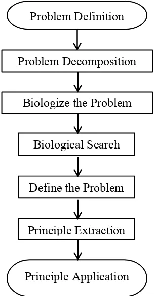
5 In general, this BID has two approaches of processes which are problem-to-solution and solution-to-problem. The problem-to-solution recognized as the problem-driven BID process needs to identify a problem, biologize the problem and the problem is solved biological (Vattam et al., 2007). Specifically, problem-driven BID process involves problem definition that need to define a specific or detectable problem of human life and for problem decomposition, it require understanding properly the meaning of the problem. While, biologize the problem means to innovate the problem in biological terms. In biological search, it needs to develop a solution that relate with the biological system. Continuously, understand the principles and techniques that used by the biologist to solve the problem via observation and experimentation. In principle extraction step, necessitates knowing the constraints of the solution that acquire. Lastly, the possible principles such as Hooke’s Law will be discovered and apply the principle in project research. Figure 1.6 shows the procedures of the problem-driven BID process.
Figure 1.6: The process flow diagram of the problem-driven BID processes
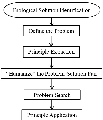
On the other hand, the solution-to-problem or also known as solution-driven BID process includes the application biologically inspired solution, principle extraction
Problem Definition
Problem Decomposition
Biological Search
Define the Problem
Principle Extraction
6 and principle application (Vattam et al., 2009). The process begins with the biological solution identification which is observing the biological solution with the casual study. In define the problem, it needs to understand the problem properly and the principles that used to solve the problem. Then, implement the applicable principles that must be suited to the engineering field.
In the problem search, it requires to know the constraint of the solution and define a new problem or stay in the previous problem. The last procedure is principle application which leads to apply the possible solution principle in the problem which then solved smoothly. Figure 1.7 shows the procedures of the solution-driven BID process. The next section will be explained about some of example that using BID concept.
Figure 1.7: The process flow diagram of the solution-driven BID processes
1.2 The Application of BID’s Concept
This section will be described the design project that successfully used Biologically-Inspired Design (BID) method. Abalone Armor is one of the examples of the Biologically-inspired design project. Abalone Armor is a bullet-proof vest which used material that combines the qualities of strength, toughness, and self-healing
Biological Solution Identification
Define the Problem
Principle Extraction
“Humanize” the Problem-Solution Pair
Problem Search
7 properties. This project had used solution-driven BID approach and problem-driven BID approach to solve the problem. Firstly, the team for this project is determined to use abalone shell or also known as nacre as their inspiration. Then, prepared and organized the problem that could be solved by the impact-resistant nacre. The team uses the abalone nacre to settle the problem of conceptualizing a bullet-proof vest. By using the problem-driven approach, several characteristics in combination the quality of material which are the strength, toughness and self-healing is chosen. For the step of biologize the problem, search the organism that had the same characteristic as mentioned above and investigated six alternative biological sources of inspiration. Based on Table 1.1, there are six biological models that had been considered in this project. This table shows the reason for considering and the reason for rejecting. The first biological model is spider silk. The spider silk is considered due to its strength per weight ratio and it is rejecting due to possible to manufacture and not strength enough to avoid from knife wounds.
Then, the lobster exoskeleton is considered because it ability to blunt cracks by using overlapping plates but the process requires water in order to be effective and would not scale-up to level required by body Armor. Next, the reason for considering the sea star is its ability to generate entire structure from a small fraction of its original mass. While, the reason for rejecting is the process of regeneration is only available to bring organism and cannot be replicated in inorganic materials. The rhino horn is considered because the strength and it is able to regrow, but it had been rejecting due to unknown rejecting. Besides, human bone is being considered because the strength, ability to regrow and modestly flexible. It has been rejected due to healing properties of bone are not viable under normal circumstances and requiring a suspension in a solution of calcium.
8
Table 1.1: Several of biological models applied for Abalone Armor (Vattam et al., 2007)
BIOLOGICAL
MODEL CONSIDERING REASONS FOR REASONS FOR REJECTING
Spider Silk Strength to weight ratio. Manufacturing on the industrial scale is not currently possible and not resistant to knife wounds. Lobster Exoskeleton Ability to blunt cracks
(dampen fractures as occur)
Sea Star Ability to generate entire
structure from a small
Rhino Horn Strength and its ability to re-grow (the same way that finger nails re-grow).
Unknown.
Human Bone Strength and its ability to re-grow. Also, it is modestly Abalone Shell Toughness, strength, and
ability to reform itself. Accepted
The analysis (as shown in Table 1.2) showed that body armor made from abalone shell would be one hundred times powerful to stop a bullet. The characteristic of self-healing mechanism was excluded from the criteria due to the mechanism was not well understood. In addition, Abalone Body Armor would ten times heavier than Kevlar Body Armor. Despite there is a light-weight characteristic, the problem definition does not state about the weight characteristic. Thus, the team had chosen Abalone Body Armor as their biological inspiration for bullet-proof vest problem. Table 1.2 depicts the different between Kevlar and Abalone Vest. Figure 1.8 and 1.9 shows the picture of Abalone shell and Kevlar Body Armor.
Table 1.2: Kevlar and Abalone types of vest (Vattam et al., 2007)
CRITERIA KEVLAR ABALONE
Thickness 0.6 cm 0.9 cm
Weight 2.3 kg 20.5 kg