White Paper
Base station antenna selection for
LTE networks
Ivy Y. Kelly, Ph.D.
Technology Development Strategist, Sprint
Martin Zimmerman, Ph.D.
Base Station Antenna Engineering Director, CommScope
Ray Butler, MSEE
Wireless Network Engineering Vice President, CommScope
Yi Zheng, Ph.D.
Base Station Antenna Senior Engineer, CommScope
Introduction 3
Antenna overview 3
LTE fundamentals 4
Selecting the optimum antenna for your network 6
Conclusion 7 References 7
About the authors 8
Introduction
Rapid mobile data growth is requiring the industry to use more sophisticated, higher-capacity access technologies like LTE, which supports many advanced antenna techniques. LTE requires precise containment of RF signals used to transmit mobile data, which can only be accomplished with high-performance antennas. This paper gives an overview of antennas and their application in practical configurations for various types of LTE antenna techniques.
Antenna overview
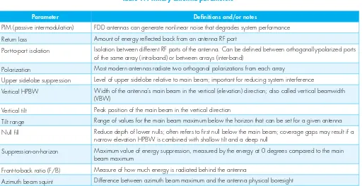
Antenna parameters can be separated into two categories, as shown below. Primary parameters (Table 1) are those specifically mentioned when defining the type of antenna used in a particular application. For a given antenna vendor, the primary parameters are enough to identify a specific model that can be used. Secondary parameters (Table 2) are those that impact performance and can be used to differentiate between similar models offered by different vendors.
Parameter Definitions and/or Notes
Number of arrays Modern antennas have 1-5 arrays or columns—possibly more if internal duplexing is used Frequency band Band of operation for each array in the antenna; affects size
Horizontal HPBW (half power beamwidth)
Horizontal (azimuth) width of antenna’s main beam; drives overlap between sectors; also called horizontal beamwidth (HBW)
Length Physical length; drives the elevation HPBW and gain; a concern for zoning and site leasing Gain Maximum power radiated in any direction; driven by length and azimuth HPBW
Table 1: Primary antenna parameters
Parameter Definitions and/or notes
PIM (passive intermodulation) FDD antennas can generate nonlinear noise that degrades system performance Return loss Amount of energy reflected back from an antenna RF port
Port-to-port isolation Isolation between different RF ports of the antenna. Can be defined between orthogonally-polarized ports of the same array (intra-band) or between arrays (inter-band)
Polarization Most modern antennas radiate two orthogonal polarizations from each array
Upper sidelobe suppression Level of upper sidelobe relative to main beam; important for reducing system interference
Vertical HPBW Width of the antenna’s main beam in the vertical (elevation) direction; also called vertical beamwidth (VBW)
Vertical tilt Peak position of the main beam in the vertical direction
Tilt range Range of values for the main beam maximum below the horizon that can be set for a given antenna Null fill Reduce depth of lower nulls; often refers to first null below the main beam; coverage gaps may result if a
narrow elevation HPBW is combined with shallow tilt and a deep null
Suppression-on-horizon Maximum value of energy suppression, measured by the energy at 0 degrees compared to the main beam maximum
Front-to-back ratio (F/B) Measure of how much energy is radiated behind the antenna
Azimuth beam squint Difference between azimuth beam maximum and the antenna physical boresight
Unfortunately, many of these parameters have not been clearly defined from an industry perspective. In an effort to bring consistency to the industry, the Next Generation Mobile Networks (NGNM) Alliance has released a BASTA white paper that suggests a single definition for each parameter.1
Beamforming antennas are becoming increasingly important in LTE networks. Column patterns, broadcast patterns, and service beams are all formed and the parameters in Tables 1 and 2 apply to each.
LTE fundamentals
Long term evolution (LTE) is a 3GPP-based standard using orthogonal frequency division multiple access (OFDMA) on the downlink and single carrier - frequency division multiple access (SC-FDMA) on the uplink. LTE supports:
• Multiple channel (e.g. carrier) sizes (1.4, 3, 5, 10, 15 and 20 MHz) with carrier aggregation (CA) up to 100 MHz
• More than 40 defined bands supporting spectrum from 450 MHz to 3.8 GHz
• Both time division duplexing (TDD) and frequency division duplexing (FDD)
• Multiple antenna-related technologies including various flavors of multiple input multiple output (MIMO) and beamforming (BF) for up to eight downlink and four uplink antennas
The first LTE specification is part of 3GPP Release 8, which was frozen in December 2008. LTE-Advanced generally refers to the LTE features that are found in Release 10 and beyond. LTE-Advanced features include CA, eight-layer DL transmission, four-layer UL transmission, and enhanced inter-cell interference coordination (eICIC).2 Release 10 features are just now
being deployed. Release 11 introduces features such as coordinated multipoint (CoMP) and further enhanced ICIC (feICIC). In March 2015, 3GPP is due to complete Release 12, which contains features such as a new 3D channel model, active antenna systems (AAS), and eight receive antennas. 3GPP has started work on features for Release 13, which should include full dimension MIMO (FD-MIMO or massive MIMO) and vertical beamforming (V-BF).
MIMO increases throughput by transmitting distinct data streams over different antennas using the same resources in both frequency and time. MIMO requires a high signal-to-interference-plus-noise ratio (SINR) and low correlation of each path. The de-correlation can be obtained by antennas (polarization or spatial diversity) or the environment (rich scattering). There are several types of MIMO: single-user MIMO (SU-MIMO), multi-user MIMO
(MU-MIMO), and massive MIMO.
SU-MIMO—or spatial multiplexing (SM)—requires multiple antennas at both ends of the link to spatially multiplex channels to a single user. SU-MIMO is most often used on the DL as there are antenna and power limits to device designs. Figure 1 shows an example of 2x2 SU-MIMO where the transmitting equipment has two antennas and the receiving equipment has two
Table 2: Secondary antenna parameters
Port-to-port tracking Difference between the azimuth patterns of the two polarizations, measured over the sector in decibels (dB)
Desired/Undesired (D/U) Measure of how well energy in the azimuth pattern is confined within the sector of operation; expressed as the percentage of the sector where the difference between the in-sector beam and out-of-sector beam exceeds a certain level in decibels (dB)
Sector power ratio (SPR) Measure of how well the energy in the azimuth pattern is confined within the sector of operation Cross-pol isolation Separation between co-pol and x-pol energy for a given port; typically measured as worst case value
Figure 1: Example of 2x2 MIMO
Multi-user MIMO (MU-MIMO) combines multiple “de-correlated” users onto the same resources. MU-MIMO does not increase peak user throughput, but it does increase average user throughput and sector capacity. Both UL and DL MU-MIMO are possible. Massive MIMO uses a two-dimensional array of closely spaced antennas, MU-MIMO with tens of devices, and an AAS.
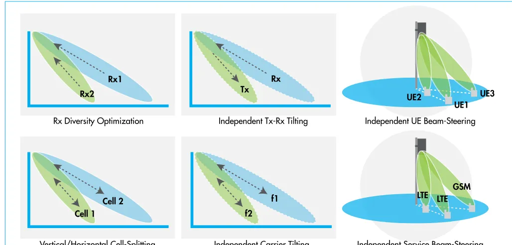
Beamformers use an array of antenna elements that are individually phased in such a way as to form beams (or nulls) in a desired direction. Typical beamforming antennas have highly correlated, closely spaced elements and columns. Passive antennas can support horizontal beamforming. An AAS integrates the active transceiver array and the passive antenna array into one radome, supporting two-dimensional (azimuth) and 3D (both azimuth and tilt) antenna array configurations. Several AAS applications are illustrated in Figure 2. An AAS base station can direct beams in different horizontal and vertical directions for different operations, frequency bands, network standards, and links (downlink and uplink).
Figure 2: AAS applications
RX
TX
data
data
UE2
LTE LTE GSM Rx2
Rx1
Cell 1 Cell 2
f2 f1 Tx
Rx
UE1 UE3
Independent UE Beam-Steering Rx Diversity Optimization Independent Tx-Rx Tilting
Independent Carrier Tilting Independent Service Beam-Steering Vertical/Horizontal Cell-Splitting
CoMP is intended to improve network performance at cell and sector edges by coordinating reception or transmission from multiple cells (either inter-site or inter-sector), providing both interference suppression and a signal strength boost. Possible CoMP techniques include joint reception for UL and joint transmission and dynamic point selection for the DL. Inter-site CoMP can require a significant increase in backhaul capacity as well as near-zero backhaul latency in order to provide capacity gain.
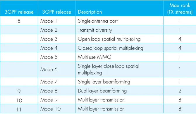
To date there are ten transmission modes defined by LTE.3 The description in Table 3 lists the
primary mode of operation, but Modes 3-10 also fall back to transmit diversity. Modes 3-5 and 8-10 have some form of MIMO, while Modes 3, 4 and 7-10 all have some form of beamforming. Modes 9 and 10 encompass SU-MIMO, MU-MIMO, and beamforming. CoMP is possible with TM9, but CoMP performance is optimized in TM10.
Uplink coverage improvement is achieved primarily by increasing the number of base station receive antennas using familiar techniques such as maximum ratio combining (MRC) and interference rejection combining (IRC). Techniques such as UL MU-MIMO and UL CoMP can provide throughput gain with no additional backhaul impacts when used inter-sector.
Selecting the optimum antenna for your network
With the many antenna techniques LTE supports—and the often highly differing antenna design requirements as well as different network designs—it can be challenging to select a single antenna to fit all scenarios. For example, SU-MIMO and Rx diversity thrive on de-correlated antennas (e.g., widely-spaced columns), while MU-MIMO and BF work best with correlated antennas. UL CoMP provides decreasing improvements with an increasing number of receivers, while MU-MIMO is most effective with four or more antennas. Many techniques have
decreasing gains with increasing inter-site distances (ISD)—such as DL CoMP, whose gains are negligible with ISDs greater than 500 meters, a configuration that is relatively common in the United States. In short, operators must choose antennas based on the techniques that will be most advantageous to their network design and needs. Table 4 summarizes some general preferences for selecting the best macro base station antenna for a given application. Primarily addressed are the 3GPP techniques found in Releases 8-11. Operators with frequency bands below 1 GHz are most likely to use a single-column cross-polarized antenna due to size
3GPP release 3GPP release Description
Max rank (TX streams)
8 Mode 1 Single-antenna port 1 Mode 2 Transmit diversity 1 Mode 3 Open-loop spatial multiplexing 4 Mode 4 Closed-loop spatial multiplexing 4
Mode 5 Multi-use MIMO 1
Mode 6 Single layer close-loop spatial
multiplexing 1
Mode 7 Single-layer beamforming 1 9 Mode 8 Dual-layer beamforming 2 10 Mode 9 Multi-layer transmission 8 11 Mode 10 Multi-layer transmission 8
≤0.65λ (0.65 wavelengths), which can give sub-optimal uplink performance compared to 1λ. The four-column antennas shown are more optimized for beamforming and likely limited to a MIMO rank commensurate with two-column antennas. Since rank is also limited by the device antennas, this may not be a concern unless operators target 8x8 DL SU-MIMO for very high peak speeds for larger fixed devices in the future. Assuming the RF environment can support ranks >4 (the most typical measured to date are rank 1-24), the four-column antenna designs
shown may be sub-optimal for 8x8 MIMO performance.
Table 4: Cross-polarized antenna selection summary
Conclusion
Antenna selection is a key decision in today’s LTE wireless network design. This paper has explored several antenna options available to RF engineers and their managers for today’s LTE networks. The function and application of base station antennas has been discussed and recommendations made for the selection of antennas in various deployment conditions.
References
1 http://www.ngmn.org/uploads/media/NGMN-N-P-BASTA_White_Paper_V9_6.pdf 2 http://www.3gpp.org/technologies/keywords-acronyms/97-lte-advanced
3 3GPP TS 36.213: “Evolved Universal Terrestrial Radio Access (E-UTRA); Physical Procedures,” 3 3GPP Technical Specification, v12.4.0, Dec., 2014.
4 http://www.ericsson.com/res/thecompany/docs/publications/ericsson_review/2010/lte-mimo.pdf Optimum application Downlink (TM) Uplink SPR VoLTE CoMP
Coverage or capacity
Single-column
45° HBW Dense site spacing, high traffic areas
65° HBW All sites, all speeds. Best all-around Good Good Inter- and intra-site
Both
85° HBW Rural sites, coverage challenges Poor Better Coverage
Two-column DL cell peak throughput; UL cell edge throughput
www.commscope.com
Visit our website or contact your local CommScope representative for more information.
© 2015 CommScope, Inc. All rights reserved.
About the authors
Ivy Kelly is a technology development strategist in the CTO office for Sprint, responsible for strategic guidance and development particularly within areas of antennas, propagation, spectrum and coexistence. She has worked for almost 15 years at Sprint in various functions including research, standards development, hardware and software development and field testing. Ivy has a bachelor of science degree in mathematics from the University of North Carolina at Chapel Hill and master of science and Ph.D. degrees in electrical engineering from The University of Texas at Austin. She is a senior member of the Institute of Electrical and Electronics Engineers (IEEE).
Marty Zimmerman is director of engineering, Base Station Antennas, for CommScope, responsible for driving the development of next-generation antenna products based on collaborations with key customers. Previously, Marty worked as RF engineering manager and senior principal engineer for the same team. Prior to that, he worked as an antenna engineer for Sinclair Technologies and Analex. Marty holds 18 US and numerous foreign patents in addition to having been published in several journals. He has a bachelor of science degree in electrical engineering from California Institute of Technology and master of science and PhD degrees in electrical engineering from University of Illinois, Urbana-Champaign.
Ray Butler is vice president of Wireless Network Engineering at CommScope, responsible for wireless architecture and technical sales leadership in outdoor RF products. Previously, Ray led the Active Wireless Products R&D team for CommScope and also worked for Andrew Corporation as vice president of base station antennas engineering, and systems engineering and solutions marketing. Ray has 30 years of experience in wireless communications having worked for AT&T Wireless, Metawave Communications and Lucent Technologies’ Bell Laboratories. He holds a bachelor of science degree in electrical engineering from Brigham Young University and a master of science degree in electrical engineering from Polytechnic University. He is a member of Tau Beta Pi national engineering honor society and Eta Kappa Nu national electrical engineering honor society.