Lag-Lead Compensator for Shape Memory Alloy
in Gripping Manipulation
Made Andik Setiawan
Politeknik Manufaktur (Polman) Timah Bangka Belitung Jln. Timah Raya Air Kantung Sungailiat, Bangka, Telp. 0717-93586
e-mail : [email protected]
Abstrak
Shape Memory Alloy (SMA) adalah salah satu jenis aktuator yang sedang banyak dipelajari pada aplikasi skala mikro dan nano. Namun di sisi lain, pengembangan pengendalian dalam skala ini masih perlu pengembangan dan penelitian lebih lanjut. Artikel ini mempresentasikan hasil evaluasi tanggapan pergerakan kendali kalang tertutup dari TiNi SMA dalam bentuk spring yang dikendalikan kompensator lag, lead dan lag-lead. SMA yang digunakan berdiameter 50 mm dan berat 350 gram. Sinyal penggerak SMA ini menggunakan modulasi lebar pusla (PWM) sinyal dengan beberapa frekuensi dan duty-cycle. Frekuensi sinyal PWM yang digunakan yaitu 12, 25, 125, 250 and 1150 Hz. Sebagai pengendali, antar muka dan pengambilan data keseleruhan sistem digunakan Lab-View dan DAQ-Card. Gripper yang
digunakan terdiri dari dua buah jari dan dapat digerakkan sampai dengan 300. Hasil eksperimen
dengan kalang tertutup akan ditampilkan dan didiskusikan pada artikel ini. Untuk aplikasi lebih lanjut, maka kendali kalang tertutup juga diuji coba menggunakan kompensator lag, lead dan lag-lead. Dengan menggunakan kendali kalang tertutup ini, maka waktu untuk mencapai rise-time menjadi lebih singkat dan tingkat galat kondisi tunak menjadi lebih kecil.
Kata kunci: Gripper, Lag-Lead Compensator, PWM, Shape Memory Alloy (SMA).
Abstract
Shape Memory Alloy (SMA) is emerging actuator for micro and nano application which is interesting to be developed. This paper presents the evaluation of close-loop controller responses of the TiNi SMA spring based gripper by introducing lag, lead and lag-lead compensator. A SMA spring has a diameter of 50 mm wire and 350 gram hanging mass. The driver of the SMA actuator uses pulse width modulation (PWM) signal and it is tested by varying frequencies and duty-cycles. The applied frequencies in this study are 12, 25, 125, 250 and 1150 Hz. Lab-View and DAQ-Card is used as a controller, interfacer and data recorder of the system. The fabricated gripper consists of two fingers and the total angular displacement of the
gripper is 300. In advanced application, the experiment coversSMA open loop and close-loop
system. The SMA response indicated that the rise-time and the steady-state error of the cloop-loop are shorter and lower than open-cloop-loop controller.
Keywords: Gripper, Lag-Lead Compensator, PWM, Shape Memory Alloy (SMA).
1. Introduction
electro-thermal driving. As the results in [1] state that “the most important two-way shape memory effect characteristic is its magnitude and response time”.
The electrical actuation of the MEMS has been widely considerate by many researchers. The electrical actuation on many applications of MEMS is voltage based controller [5], current based controller [1] and frequency based controller [4].
SMA actuators has a good high power/ weight ratio, produce a large displacement in a limited space, it has good transformation temperatures and an excellent mechanical properties such as ductility and toughness [5]. Gripping principles include vacuum suction, shape memory effect, piezo actuation, magnetic actuation, electrothermal effect and also laser trapping.
The gripper mechanism which the actuation is provided by SMA and driven by an electrical has published in [6]. The other grippers have also been published and developed by researcher for any purposes, such as the electrostatic microgripper [7], development of the endoscopic tip actuator [8], the microgripper for holding the chip [9], and also the electric piston for the gripper finger [4].
Figure 1. Electrostatic microgripper, combination of a linear motor, an amplification mechanism and a grasping stage [7]
Figure 2. The endoscopic tip actuator [8]
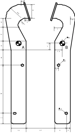
2. Methods and Set-Up 2.1 Gripper Design
The movement of the gripper in this study is actuated by a SMA spring. The gripper mechanism (in mm) is shown in Figure 3. The material of the gripper is with a thickness of 2 mm Aluminium (Al). The hole of A and B are used as a center of movement of the gripper. This hole is also used to assemble the position sensor. The bottom holes are used for the spring hook.
11 2 7 1 5
3
5 7
4 1 1
4
2
∅ ∅ ∅ ∅
2
∅ ∅∅ ∅
53 16
5
∅ ∅∅ ∅
10 7
7 . 5
R1 5
10 R10
3 15
1 5
A B
Figure 3. Gripper consisting of two fingers
6 Vo lt
5
4
3
2
1
500 10 00 1500 2000 25 00 3000 35 00
Rotation
O
u
t
o
f
W
o
rk
in
g
A
re
a
Figure 4. Voltage to degree chart converter of potentiometer.
2.2 Position Sensor
The position sensor used was a rotary potentiometer with a 5KΩ of resistance. This potentiometer has shaft diameter of 5.5 mm, shaft length of 10 mm and linear resistance (type B). The total rotation of this potentiometer is 3000. In this study, the gripper movements are measured by the position sensor by employing a 5 KΩ of potentiometer. At the default position of gripper, the output voltage of the potentiometer is 3 volt and at the maximum retraction position of the spring is 2.7 volt. The total angular rotation of the gripper (θ) is 150+150=300. The voltage of power supply is given 6 volt. The converter chart (voltage to degree) is illustrated in Figure 4.
Figure 5. Block diagram of the system
2.3 Programming
send the voltage input of the pulse width modulation (PWM) circuit. Another trademark of National Instrument Corporation used in this study is DAQ card PCI NI-6024E.
The relationship between LabView, DAQ card, PWM circuit, the spring and the position sensor is illustrated in Figure 5 and the front panel of Lab View presented in Figure 6.
Figure 6. LabView front panel of gripper angular measurement.
3. Results and Discussions
3.1 SMA Spring Responses to PWM Signal
The first performance test is to analyse the movement responses of SMA Spring actuated by varying frequencies and duty cycles of PWM signal. The frequency of PWM signal used is 12, 25, 125, 250 and 1150 Hz and duty cycles varying from 20% to 90%. The movement response of SMA spring to achieve the position destination (time versus displacement) is recorded by Lab View and presented in Figure 7. According to Figure 7 the fastest response of the SMA spring is actuated by 125 Hz PWM signal.
20 30 40 50 60 70 80 90
0 5 10 15 20 25 30 35 40
The Spring Movements Actuated by PWM signals
PWM Duty Cycle(%)
T
im
e
(
s
e
c
o
n
d
)
12Hz 25Hz 125Hz 250Hz 1150Hz
Figure 7. Spring movements actuated by several frequencies of PWM signals.
Voltage parameter sent to PWM circuit
Absolute angular position of the gripper electronic signal from the position sensor
3.2 Lead and Lag Compensator
In this study, a number of tests on position control of the gripper are conducted by using lag, lead and lag-lead compensators. The signal in previous experimentations is employed in this experiment. The signal employed is 125Hz of PWM signal due to this signal had a faster movement response.
The transfer function of the lead compensator is [10]:
T
where α and T are determined from the angle deficiency. Kc is determined from the requirement of the open-loop gain and
1
T
is less than1
α
T
.To simplify the calculation, it can be assumed that:
a
By inserting equation (2) and equation (3) into equation (1), it can be derived that:
b By using Tustin’s method (bilinear approximation) [10], the equation (4) can be converted into Z domain. The Tustin’s method is given:
) By some mathematical manipulation, equation (6) becomes
E(z)(2Kc+aTKc)+z-1E(z)(-2Kc+aTKc)+U(z)z-1(2-bT)=U(z)(2+bT) (7) e(k)(2Kc+aTKc)+e(k-1)(-2Kc+aTKc)+u(k-1)(2-bT)=u(k)(2+bT) (8) The output of the lead compensator is:
bT) The difference of lag and lead compensator [10] is:
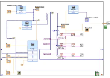
specification and PWM input requirements. The block diagram and the LabView program of the lag and the lead compensator are presented in Figure 8 and Figure 9, respectively.
Sensor
Figure 8. Block diagram of the lead and the lag compensator.
Figure 9 LabView program of the lag and the lead compensator.
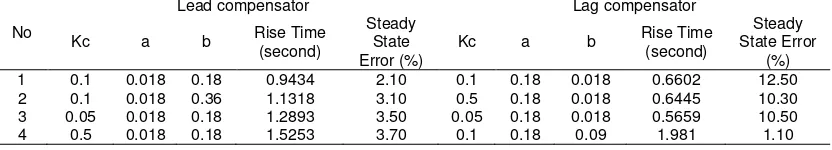
The responses of the closed-loop control with the lead compensator by using different gains are shown in Figure 10 and the lag response is presented in Figure 11. The rise time and the steady state error of the lag compensator and the lead compensator are presented in Table 1.
0 0.5 1 1.5 2 2.5 Lead Compensator Responses
Time (second)
Kc=0.1 a1=0.018 b1=0.18
0 0.5 1 1.5 2 2.5 3 3.5 4
Lead Compensator Responses
Time (second)
Kc=0.1 a1=0.018 b1=0.36
0 0.5 1 1.5 2 2.5 3 3.5 4 4.5
Lead Compensator Responses
Time (second)
Kc=0.05 a1=0.018 b1=0.18
a. b. c.
0 0.5 1 1.5 2 2.5
Lag Compensator Responses
Time (second)
Kc=0.1 a1=0.18 b1=0.018
0 0.5 1 1.5 2 2.5 3 3.5
Lag Compensator Responses
Time (second)
Kc=0.5 a1=0.18 b1=0.018
0 0.5 1 1.5 2 2.5 3 3.5 4
Lag Compensator Responses
Time (second)
Kc=0.05 a1=0.18 b1=0.018
a. b. c.
Figure 11. The lag compensator response with (a). Kc=0.1, a=0.18 and b=0.018, (b). Kc=0.5, a=0.18 and b=0.018, (c). Kc=0.05, a=0.18 and b=0.018.
Table 1. The response of the closed-loop control with the lead and the lag compensator
No
Lead compensator Lag compensator
Kc a b Rise Time State Error
(%) 1 0.1 0.018 0.18 0.9434 2.10 0.1 0.18 0.018 0.6602 12.50 2 0.1 0.018 0.36 1.1318 3.10 0.5 0.18 0.018 0.6445 10.30 3 0.05 0.018 0.18 1.2893 3.50 0.05 0.18 0.018 0.5659 10.50 4 0.5 0.018 0.18 1.5253 3.70 0.1 0.18 0.09 1.981 1.10
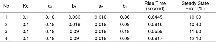
3.3 Lag-Lead Compensator
The transfer function of the lag-lead compensator is [9]:
To simplify the calculation, it can be assumed that:
1
By inserting equation (11) and equation (12) into equation (10), it can be derived that:
compensator is:
)
where A=A1+A2
) 2
2 4 )(
( 2 1 1 2 2
2 ek Kc aTKc aTKc aaT Kc
A = + + + (16)
) 2 8 )( 1 ( ) 2
2 4 )( 2
( 1 2 2
2 2 1 1
2T bT bbT uk bbT
b k
u
B=− − − − + − − − + (17)
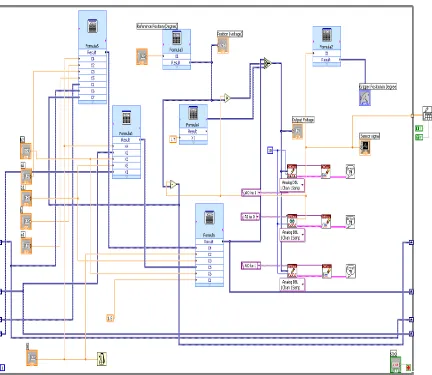
The block diagram and the LabView program of the lag-lead compensator are presented in Figure 12 and Figure 13, respectively. The responses of the closed-loop control with the lag-lead compensator by using different gains are shown in Figure 14. The rise time and the steady state error of the lag-lead compensator are presented in Table 2.
+ +
+ +
2 2
1 1
b s
a s b s
a s Kc
Figure 12. The block diagram of the lag-lead compensator.
0 0.5 1 1.5 2 2.5 3
Lag Compensator Responses
Time (second)
Kc=0.1 a1=0.18 b1=0.036 a2=0.018 b2=0.36
0 0.5 1 1.5 2 2.5 3
Lag Compensator Responses
Time (second)
Kc=0.1 a1=0.18 b1=0.018 a2=0.018 b2=0.09
0 0.5 1 1.5 2 2.5 3 3.5
Lag Compensator Responses
Time (second)
Kc=0.1 a1=0.18 b1=0.09 a2=0.018 b2=0.18
a. b. c. Figure 14. The lag-lead compensator response with (a). b1=0.036, a2=0.018 and b2=0.36,
(b). b1=0.018, a2=0.018 and b2=0.09, (c). b1=0.09, a2=0.018 and b2=0.18.
Table 2. The response of the closed-loop control with the lag-lead compensator
No Kc a1 b1 a2 b2 Rise Time
(second)
Steady State Error (%)
1 0.1 0.18 0.036 0.018 0.36 0.6445 10.00
2 0.1 0.18 0.018 0.018 0.09 0.5816 10.40
3 0.1 0.18 0.09 0.018 0.18 0.5659 11.60
4 0.1 0.18 0.09 0.018 0.09 0.6917 12.10
4. Conclusions
A number of tests on the performance characterization of the SMA spring were conducted. The performance characterization experiment of the SMA spring is the movement response. The movement response experiment is conducted with applying different frequencies and different duty cycles of PWM signals. The 125 Hz frequencies are likely to have the fastest response of the SMA spring.
In this study, a number of tests on position control of the gripper are also conducted by using lag, lead and lag-lead compensators. The tuning of the gain is based on experimentally tuning. The experiment results indicated that the rise time of the gripper system was shorter (approximately 10 times) than the open-loop controller. On the other hand the smallest steady state error is obtained by lead compensator. The lag, lead and lag-lead compensator are likely to be reliable and suitable controllers for close loop controller of the SMA spring for the future.
One of the SMA characteristic is that the SMA has a fast response when heated but slower on cooling. The SMA has disadvantage at cooling problems. By developing the cooling system of the SMA, the performance of the gripper will be significantly improved.
References
[1] Wang ZG, Zu XT, Feng XD, Zhu S, Bao JW, Wang LM. Characteristics of two-way shape memory TiNi springs driven by electrical current. Materials and Design. 2004; 25(8): 699– 703.
[2] Wolf RH, Heuer AH. TiNi (Shape Memory) Films on Silicon for MEMS applications. Journal
Of Microelectromechanical Systems. 1995; 4(4): 206-212.
[3] Fohse M, Kohlmeier T, Gatzen HH. Thinfilm technologies to fabricate a linear microactuator. Sensors and Actuators A: Physical, 2001; 91(2): 145-149.
[4] Cordova FG, Coronado JL, Gonzhlez AG. Design of an anthropomorphic finger using
shape memory alloy springs. IEEE SMC '99 Conference on Systems, Man, and
Cybernetics. Tokyo. 1999; 2: 794–799.
[5] Zhang H, Bellouard Y, Burdet E, Clavel R, Aun-Neow P, Hutmacher DW. Shape Memory
Alloy Microgripper for Robotic Microassembly of Tissue Engineering. IEEE International
[6] Menciassi A, Moglia A, Gorini S, Pernorio G, Stefanini C, Dario P. Shape memory alloy clamping devices of a capsule for monitoring tasks in the gastrointestinal tract. Journal of
Micromechanics and Microengineering. 2005; 15(11): 2045–2055.
[7] Millet O, Bernardoni P, Régnier S, Bidaud P, Tsitsiris E, Collard D, Buchaillot L. Electrostatic actuated micro gripper using an amplification mechanism. Sensors and
Actuators A: Physical. 2004; 114(2): 371–378.
[8] Peirs J, Reynaerts D, Van-Brussel H. A Micro Robotic Arm for A Self Propelling
Colonoscope. 6th International Conference on New Actuators. Bresmen. 1998: 576-579.
[9] Cecil J, Gobinath N. Development of a virtual and physical work cell to assemble micro-devices. Robotics and Computer-Integrated Manufacturing. 2005; 21(4): 431–441.
![Figure 2. The endoscopic tip actuator [8]](https://thumb-ap.123doks.com/thumbv2/123dok/247613.503881/2.595.159.438.276.477/figure-endoscopic-tip-actuator.webp)