Simulation of Single-phase to Ground Fault
to Anticipate Against the Sympathetic Tripping
Phenomena
Arief Goeritno
*, Saidah
+*Permanent Lecturer at the Department of Electrical Engineering – Faculty of Engineering – Bogor Ibn Khaldun University
Employee of the State Electricity Company, Distribution and Center for Load Regulator, Regulating Area for Maintenance, Bogor
Abstract
—
Simulation of single-phase to ground fault (1Φ-ground fault) to anticipate against the sympathetic tripping phenomena have been done. Results include are the current value of single-phase to ground fault and capacitive current and the value of adjustment current of Ground Fault Relay (GFR) is 0.5 amperes (10% of the value of the ratio of current transformer in term of the secondary side) for all feeders, the selected time setting of GFR is 0.30, and Time Multiplier Setting of Ground Fault Relay values obtained for all feeders is 0.15 (rounded from 0.11). The largest current value occurred in a location 25% length of the line for all feeders. It was influenced by the value of reactance as the denominator value, the smaller the percentage of length of the line, the greater the value of the fault current. The value of adjustment current was obtained at 0.5 amperes and working time of Ground Fault Relay not more than 0.4 seconds.Keywords: single-phase to ground fault, sympathetic tripping, setting of GFR.
I. INTRODUCTION
Single phase to ground fault (1Φ-g fault) is a phenomenon that most often occurs in the electrical power system (about 85%) of the entire phenomenon of short circuit fault, symmetry or not symmetry [1]. To overcome this, the 20 kV distribution network system in particular needs Ground Fault Relay (GFR) to be coordination of relay protection system against the fault to ground in a single bus bar. GFR should has this level of reliability, as desired, so as to isolate the scope of faulted areas as small as possible and to separate the faulted areas as quickly as possible [1,2]. The role of fault current value for adjustments in GFR operations is an important role in efforts to overcome the single-phase to ground fault. Adjustment to GFR based on the calculation of length of the line of feeders, where it caused a major disruption impedance.
When the single-phase to ground fault will cause the emergence of current to ground fault that accompanied the emergence of impedance (fault impedance,
Z
fault). Value ofthe ground fault current and impedance fault is strongly influenced by the location of the point of interruption of the power source, in addition to the distribution network is very
dynamic due to changes in network length that is affected by the load regulation, fault localization, or release of voltage because of maintenance or network explanation [3]. It may lead to adjustment of the value of certain currents in GFR is not optimum, thereby potentially causing failure of coordination between GFR in the power system. Failure of coordination between GFR in a single bus bar is joined functioning of GFR in feeders that are not susceptible to interference. That phenomena is better known as the sympathetic tripping [3,4,5].
Based on the above description, it is necessary to simulate the phenomenon of single phase to ground fault for anticipating the occurrence of sympathetic tripping through variations in the determination of the location of point disorder as measured from the tip of feeder side resources to the acquisition value 1Φ-ground fault currents and capacitive currents in each feeder. Capacitive currents are taken into account is the capacitive currents when the emergence of 1Φ -ground fault currents that have the greatest value, so that capacitive currents will be obtained also contributions from other feeders that are not susceptible to interference. After the current acquisition, establishment and adjustment of the flow of time in GFR can be used to obtain the value of GFR for TMS every protection system can be coordinated and sympathetic tripping does not occur among the feeders that are in a power bus.
The purpose of this simulation, obtained: (a) the current value of single phase to ground fault and capacitive currents based on the percentage of long-feeders aided spreadsheet application program and (b) value of Time Multiplier Setting (TMS) based on tuning the current and GFR working time based on the current value of single-phase to ground fault that may arise and are influenced by the percentage of length of the line feeders.
II. MATERIAL AND METHOD OF RESEARCH
A. Material of Research
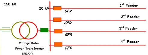
Voltage Ratio Power Transformer
150/20
20 kV
150 kV 1st Feeder
3rd Feeder 2nd Feeder
4th Feeder GFR
GFR
GFR
GFR
Fig. 1 Schematic diagram of the structure of the distribution network in the form of power transformer with four its feeders
Technical data of each 20 kV feeder, as shown in Table I.
TABLE I
TECHNICAL DATA OF EACH 20 kV FEEDER
Component 1st Feeder 2nd Feeder 3rd Feeder 4th Feeder Z1/km = Z2/km 0.103 +
j
0.364 Ω
0.103 +
j
0.364 Ω
0.103 +
j
0.364 Ω
0.103 +
j
0.364 Ω
Z0/km 0.270 +
j
0.580 Ω
0.270 +
j
0.580 Ω
0.270 +
j
0.580 Ω
0.270 +
j
0.580 Ω
The longest line 15 kms 14 kms 20 kms 16 kms Z1 = Z2 of the
line 1.545 +
j
5.46 Ω
1.442 +
j
5.096 Ω
2.06 +
j
7.28 Ω
1.648 +
j
5.824 Ω
Z0 of line 4.050 +
j
8.700 Ω
3.780 +
j
8.120 Ω
5.400 +
j
11.600 Ω
4.320 +
j
9.280 Ω
Capasitance, Ce (
X
CE)0.03 μF/km 0.02 μF/km 0.05 μF/km 0.06 μF/km
Length total of the line
200 kms (included the
branching)
80 kms (included the
branching)
80 kms (included the
branching)
80 kms (included the
branching)
The other data regarding schematic diagram for 20 kV distribution network structure from the power transformer output, namely:
Capacity of the power transformer
: 60 MVA
Percent of impedance (
%
Z
) : 11% (in terms of the primary voltage) Primary voltage (V
pr.) : 150 kVSecondary voltage (
V
sec.) : 20 kVDelta winding : there is, then there is a zero sequence reactance,
0
X
Nominal current (
I
nom._20kV ): 1732.0508 amperes (in terms of the secondary voltage)
Resistance of Grounding (
R
ground ): 12 Ω (in terms of the secondary voltage).
B. Method of Research
B.1. Initial calculation
Based on Table I indicated, that in this study was conducted the simulations using a spreadsheet computer application program for the initial calculations. The result of
term of the primary side, (b) the base impedance, (c) source impedance (
Z
source), (d) zero sequence reactance power transformer with respect to the presence or absence delta winding, (e) nominal current value in terms of the secondary voltage, and (f) the value of total capacitance of the line.(a)The value of the short circuit capacity by determinating value of short circuit current in term of the primary side Short circuit capasity (
MVA
sc) at bus-150 kV was depend on its short circuit value. Substitution of primary voltage value and short circuit current value was obtained short circuit current capasity. Correlation between short circuit current and capacity in terms of the primary voltage (the voltage side of 150 kV), as shown in Table II.TABLE II
CORRELATION BETWEEN SHORT CIRCUIT CURRENT AND CAPACITY IN TERMS OF THE PRIMARY VOLTAGE
(THE VOLTAGE SIDE OF 150 kV) Short Circuit Current
(kA)
Short Circuit Capacity (MVA)
16.00 4,157
16.50 4,287
17.00 4,417
17.50 4,547
19.00 4,936
20.00 5,196
21.00 5,456
(b)Base impedance value
Calculation of base impedance value on the power transformer based on technical data, that power transformer capacity is 60 MVA, voltage ratio is 150/20 kV, and grounding reactance in terms of the secondary voltage is 12%. Base impedance on power transformer (value of 100%) in terms of the voltage side of 20 kV was calculated, thus obtained:
6.67
60 ) 20
( 2
2 sec sec
MVA kV
Z ondary ondary . Grounding reactance
of the power transformer in terms of the secondary is equal 12%, thus obtained XTD12%6.670.8004 . Reactance value that obtained are positive and negative sequence reactance. To determine the value of the power transformer percent impedance when viewed from the side of the secondary voltage (20 kV), thus obtained
0.73333360 ) 20 ( % 11 %
2 .
secondary
Z .
(c)Source impedance value
Source impedance in the side of 20 kV can be calculated. Calculate the source impedance (
Z
source) under thecapasity at 4,157 MVA (for 16 kA short circuit current), thus obtained sc prim ary source MVA k V Z 2 ) ( 157 , 4 500 , 22 157 , 4 ) 150 ( 2 source
Z 0+
j
5.412557 Ω.To calculate the impedance values of the side of 20 kV each feeder, the impedance in term of the voltage side of 150 kV is transformed to the voltage side of 20 kV. Schematic diagram of the impedance value transformation from the voltage side of 150 kV to 20 kV, as shown in Figure 2.
Fig. 2 Schematic diagram of the impedance value transformation from the voltage side of 150 kV to 20 kV
Explanation of the calculation, the power in term of the voltage side of 150 kV equal the power in term of the voltage
side of 20 kV, then
primary primary primary primary Z kV Z
kV )2 ( )2
(
. Substitution
value of k Vprimary = 150 kV; k Vsecondary = 20 kV; and
primary
Z = 0 + j 5.412557 Ω; then
5.412557) 150 ( ) 20 ( ) ( ) ( 2 2 2 2 sec
sec primary
primary ondary ondary source Z kV kV Z =
0 + j 0.096 Ω. Sequence impedance applies to both positive and negative, so that the value of equivalent impedance in the voltage side of 150 kV equal in the voltage side of 20 kV. Equivalent circuit of Thevenin in the voltage side of 20 kV , as shown in Figure 3.
Fig. 3 Equivalent circuit of Thevenin in the voltage side of 20 kV
(d)Zero sequence raectance of the power transformer with respect to the presence or absence delta winding
Value of zero sequence reactance on the power transformer due to the presence of the delta winding is calculated to obtain
X
0= 3 xj
0.73333 =j
2.2 Ω.(e)The value of nominal current in terms of the secondary voltage
Nominal current value in terms of the secondary voltage (the voltage side of 20 kV) is calculated, so that
0508 , 1732 3 20 1000 60 3 ) ( 1000 ) ( sec 20 _ min ondary kV al no k V MVA
I amperes.
(f) The value of total capasitance of the line
The value of total capacitance of the line (Xtotal_of_network)
was calculated in order to obtain their respective feeders, namely:
1st Feeder: Xtotal_of_network
200 10 03 , 0 50 142 , 3 2 1 6
=
j
530,51648 Ω; 2nd Feeder: Xtotal_of_network
80 10 02 , 0 50 142 , 3 2 1 6
=
j
1989,4368 Ω; 3rd Feeder: Xtotal_of_network
80 10 05 , 0 50 142 , 3 2 1 6
=
j
795,77472 Ω.; and 4th Feeder: Xtotal_of_network
80 10 06 , 0 50 142 , 3 2 1 6
=
j
663,1456 Ω.B.2. Advanced Calculation
Furthermore, advanced calculation according to the purpose of the study, namely: (a) The calculation of short circuit current and capacitive current in each feeder based on the percentage of length of the line (25%, 50%, 75%, and 100%) and (b) the calculation for adjusting of GFR and relay working time of the type of definite and inverse in the feeder for single-phase to ground fault by the percentage of length of the line (25%, 50%, 75%, and 100%).
III. RESULT AND DISCUSSION
A. The Value of Current of Single-phase to Ground Fault and Capasitive Current per Phase at Each Feeder
Single-phase to ground fault (
I
1g_fault ) has simulated occur along the feeders and focused on the percentage of the distance. The distance was chosen, namely 25%, 50%, 75%, and 100% length of the line that has measured from the source, while the capacitive current per phase is only for 25% length of the line. Also note the data, such as: (i) secondary voltage (V
secondary) = 20 kV; (ii) Resistance of Grounding,grounding
R = 12 Ω; (iii)
%Z secondary = 0.733333; (iv)
Z
source
secondary= 0 + j 0.096 Ω; and (v)X
0= 3 xj
0.73333 =j
2.2 Ω. Using the technical data in Table I and note of the data, calculation of single-phase to ground fault and calculation of capacitive current per phase at each feeder.TABLE III
THE CURRENT VALUE OF SINGLE-PHASE TO GROUND FAULT SIMULATION AND PHASE CAPACITIVE CURRENT PER PHASE
BASED ON THE PERCENTAGE OF LENGTH OF THE LINE
Based on Table III is shown, that the largest current value of single-phase to ground fault occurring in 25% length of the line in each feeder. It was strongly influenced by length of the line, where the value of impedance as the divisor is the smallest value. The value of line impedance at 25% length of the line is worth less than the value of line impedance at 50% length of the line. Similarly value of line impedance at 50% length of the line is worth less than the value of line impedance at 75% length of the line, also value of line impedance at 75% length of the line is worth less than the value of line impedance at 100% length of the line.
The values of
I
CE1,I
CE2,I
CE3, andI
CE4 are calculated to obtanining the simulation of its calculating only 25% of length of the line, as desired only to 25% of length of the line. It relates to the application of the current settings on the field for only 25% of length of the line[3]. The value ofI
CE1 is higher than the others. It relates to the length total of the line. Capacitive currents (I
CE ) that flows as a result of contributions from the other feeders are calculated, namely: (a) At 1st Feeder for =I
CE2 +I
CE3 +I
CE4 = 113,2amperes;
(b) At 2nd Feeder for =
I
CE1 +I
CE3 +I
CE4 = 161,1 amperes;(c) At 3rd Feeder for =
I
CE1 +I
CE2 +I
CE4 = 134,9 amperes;(d) At 4th Feeder for =
I
CE1 +I
CE2 +I
CE3 = 126,2 amperesThese results indicate, that the capacitive current in the 2nd feeders has the highest value, where value is affected by the current of single-phase to ground fault at feeder, while capacitive currents that occured at the 2nd feeder itself is the smallest.
B. The Value of TMS through Determine of the Value of Adjustment for the Value of Current Time of GFR
Setting the value of current and working time of GFR obtained through the simulation of single-phase to the ground fault along the feeders. The data have been obtained, is the number of coils on the secondary side of current transformer that obtained from the ratio of the current transformer (2000/5).
Obtaining the value of adjusting the current of GFR, namely:
ct of side coils
of number
Iset.0,1 . . _sec. _ _ = 0,1 x 5 = 0.5 amperes for all feeders;
Choosing
t
set.= 0.30; the value of TMS of GFR was obtained for all feeders as amount as:. 02
, 0
.
14 , 0
1
set set
hs
t I
I
TMS
= 0,30
14 , 0
1 53 , 70
1 , 893 0,02
= 0.11
(rounded to 0.15).
Value of
I
set.= 70.53 amperes obtained from 10% of the smallest fault current that occurs at the fault location by 100% interruption length of the line of the 1st feeders (is the farthest distance from the source).The calculation for the acquisition value, more focused to 25% length of the line, because at the fault location has the greatest fault current. The relationship between the ratio of current transformers and the current adjustment, and TMS of GFR, as shown in Table IV.
TABLE IV
THE RELATIONSHIP BETWEEN THE RATIO OF CURRENT TRANSFORMERS AND THE CURRENT ADJUSTMENT, AND TMS OF
GFR
Setting the value of current and working time of inverse type of relay is elected for the inverse type of relay, because application of the GFR itself. After adjusting the current is known, the next calculation is to determine the extent of inverse selectivity of GFR in each feeder by substituting the value of
I
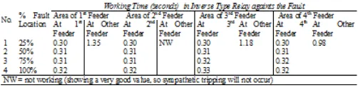
sc_1in GFR. The time of adjustment based on the percentage of the fault location when in the feeder itselt was faulted and if there is a fault in the other feeders is the selectivity of working time of inverse type relay. The results of calculation the value of selectivity of working time in inverse type relay for GFR, as shown in Table 5.TABLE V
THE RESULTS OF CALCULATION THE VALUE OF SELECTIVITY OF WORKING TIME IN INVERSE TYPE RELAY FOR GFR
operating after 1.35 seconds. Likewise with impaired the single-phase to ground fault that occurred in the 2nd feeder, the 3rd feeder, or 4th feeder. Operation of the GFR accelerated by the presence of capacitive current per phase (
I
CE) when thereis a single-phase to ground fault, where a part of
I
0 will be brought into the GFR.IV. CONCLUSIONS
Referring to the result and discussion, the following conclusions can be drawn:
(1) The largest current value of single phase to ground fault occurred in a location 25% length of the line for all feeders. It was influenced by the value of reactance as the denominator value, the smaller the percentage of length of the line, the greater the value of the fault current; The value of capacitive currents in the 2nd feeder has the highest value, because the capacitive current that occured in the 2nd feeder is most small, where the value is influenced by the value of single-phase to ground fault current in this feeder;
(2) The value of adjustment current was obtained at 0.5 amperes and working time of GFR not more than 0.4 seconds; the value of adjustment current will not result a sympathetic tripping, if the phenomena of single phase to ground fault occurs.
ACKNOWLEDGMENT
Many thanks go to Mr. Syofyan Rasiman, for all his help in the smooth running of the administration to gain the necessary permissions.
REFERENCES
[1] B. Ravindranath, and M. Chander, “Power System Protection and Switchgear”, New Delhi: Wiley Eastern Limited, 1977, pp.6-11. [2] Rao, T.S. Madhava, “Power System Protecton, Static Relays”, New Delhi:
Tata-McGraw-Hill, 1979, pp. 10-11.
[3] State Electricity Company, ”Buku Petunjuk Operasi dan Pemeliharaan Peralatan Untuk Rele Proteksi”, Unpublished.
[4] M. Sengul, et al, “Case Study of Sympathetic Interaction between
Transformers Caused by Inrush Transients”, Paper No. IPST’05–125, Presented at International Conference on Power Systems Transients
(IPST’05) in Montreal, Canada on June 19-23, 2006.
http://ipstconf.org/papers/Proc_IPST2005/05IPST125.pdf.