ABSTRACT
The present invention related to automated guided cart (AGC) particularly to cost-effectiveness, light duty vehicle, which is specifically adapted for use in light manufacturing shop floor. This AGC followed a magnetic guide taped on floor to move goods or material from one point to another under PIC control. The AGC system employ specifically designed carts, which are configured particularly to carry components such as automobile chassis or assembly components in an automobile assembly operation. Generally, the method to achieve the objectives, it consists of designation stage, procurement preparation stage, material preparation stage, fabrication stage, and examination stage. This project involved design and development of the AGC system through the engineering skills via mechanical calculation and analysis, material selection, electrical circuit design, and programming of the PIC controller. In the implementation stage, a light duty AGC produce and applicable to industrial environment to accomplished the project.
ABSTRAK
ACKNOWLEDGEMENT
I would like to express my gratitude to all those who gave me the possibility to accomplish this project of manufacturing engineering bachelor’s degree entitled automated guided cart. I want to thank the Department Managemtnt Faculty of Manufacturing of Universiti Teknikal Malaysia Melaka (UTeM), Prof. Dr. Mohd. Razali b. Muhamad and giving me permission to commence this project in the first instance, approved the title of project proposed. I have furthermore to thank the Management of Project Sarjana Muda, Sivarao a/l Subramonian, and Head of Department of Robotic and Automation, Dr. Zamberi bin Jamaludin who gave and confirmed this permission and supported me to progressing with my project.
I am deeply indebted to my supervisor, Puan Nur Aidawaty bt. Rafan and principle co-supervisor, Puan Silah Hayati bt. Kamsani from the Department of Robotic and Automation of UTeM whose help, stimulating suggestions, technical information, and encouragement helped me in all the time of project and writing of this report.
My colleagues from 4BMFA of UTeM supported me in my research work. I want to thank them for all their help, support, interest and valuable hints. Especially I am obliged to Mr. Lim, Lee Wai Keong, Tan Sia Peng for the great help in difficult times and suggestions for improvement.
TABLE OF CONTENT
Abstract i
Abstrak ii
Acknowledgement iii
3.3 Design Requirement 28
4.2.1 Gear Geometry Computation 41
4.2.2 Shaft Design 42
4.2.3 Bearing Selection 44
4.3 Frame Design 45
4.3.1 Technical Drawing 48
4.4 Motor Drive Circuit Board Designation 51 4.5 Microcontroller Electronic Circuit Designation 53
4.6 Magnetic Sensor 54
5. RESULT AND DISCUSSION 56
5.1 Mechanical Structure 56
5.2 Controller 58
5.2.1 Microcontroller Electronic Circuit Board 58
5.2.2 Microchip Pin Assignment 61
5.2.3 Motor Control Electronic Circuit Board 62 5.3 Magnetic Sensor Electronic Circuit Board 64
5.4 PIC Comment Programs 67
5.4.1 Microcontroller Language (C Language) 67
6. CONCLUSION AND RECOMMENDATION 74
6.1 Conclusion 74
6.2 Recommendation 75
REFERENCE 76
APPENDIX A
APPENDIX B
APPENDIX C
APPENDIX D
APPENDIX E
LIST OF TABLES
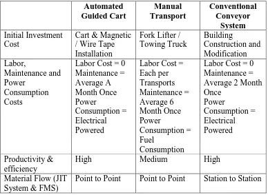
1.1 Comparison of the Methods of Material Handling.
2.1 Uses of Some Steels 2.2 Aluminum Alloy Groups
2.3 Common Aluminum Alloys and Their Uses 2.4 AC Motor Voltage.
2.5 AC Motor Speeds for 60 Hertz Power 2.6 DC Motor Voltage Ratings
3.1 Characteristics of the Material Elements.
3.2 Alloy Steel and Aluminum General Physical Properties. 3.3 Microcontrollers Device Overview and Its Properties 3.4 Microcontroller Features As Guide to Selection
3.5 Characteristics and the Features of Unipolar Type Magnetic Sensors. 3.6 Characteristics and the Features of Bipolar Type Magnetic Sensors.
4.1 Summary of the Comparison between Desired Value and Selected Value. 4.2 Pin assignment and its function.
4.3 General electrical and magnetic specifications.
5.2 DIP switch operation direction 5.3 Logic function of the motor driver
LIST OF FIGURES
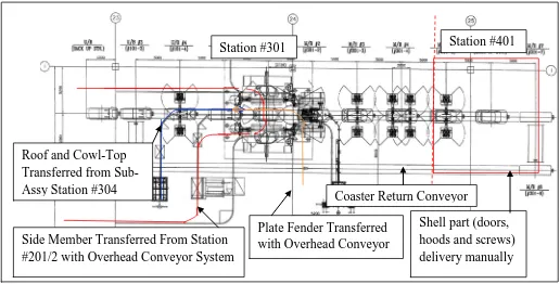
1.1Production Layout Illustrated the Material Handling System in Present Practice.
2.1 Plan View of an Exemplary Embodiment of the Information Sensing Portion of the Guided System.
2.2 The Diagrammatical Perspective View of the AGV Adapted to Move Automatically Along an Optically Defined Path for Carrying a Load From a Starting Point to an Arrival Point.
2.3 A Diagrammatic Side Elevation View of a Self Guided Vehicle 2.4 Single-phase AC Power and Three-phase AC Power
2.5 General Form of Motor Performance Curve 2.6 Pair of Spur Gears. The Pinion Drives the Gear 2.7 Hall-Effect Principle With No Magnetic Field Present 2.8 Hall-Effect Principle With Magnetic Field Presents 2.9 Circuit of an IR Emitter and IR Phototransistor
2.10 Circuit and Diagram of an Infrared Reflectance Sensor.
3.1 Basic Draft of the Options for the Drive Mechanism of Automated Guided Cart.
3.4 Force Distributed on the Cart.
4.1 Design Sketch of the Drive Mechanism (Single Stage Gear System) and Its Main Components.
4.2 Power Flow Through the Gear.
4.3 Direction of Force Distribution on Gear.
4.4 Graphical Representative of Force, Shearing Force and Bending Moment of the Gear.
4.5 Force Distortion on the Frame of the Cart.
4.6 Graphical Representative of Force, Shearing Force and Bending Moment of the Frame.
4.7 COSMOSX Analysis of the Aluminum Square Hollow Bar (20x20x1/4) 4.8 Assembly CAD Drawing of the AGC.
4.9 Frame CAD Detail Dimension Drawing. 4.10 Detail CAD Drawing of the Drive Mechanism.
4.11 Pin connection of the dual-bridge microchip Multiwatt15 4.12 Full-bridge circuit electronic circuit diagram.
4.13 Design circuit of the microcontroller board associated with the burner function.
4.14 Mechanism of turning performed by three magnetic sensors. 4.15 Dimension of the magnetic sensor.
4.16 Designation of the magnetic sensors circuit
5.1 Top view of the structure of Automated Guided Cart 5.2 Dimension of the Automated Guided Cart
5.3 Gear mechanism using spur gear system to drive the cart 5.4 Microcontroller electronic circuit board
5.5 Dual Interchange Pin (DIP) Switch 5.6 Voltage regulator 7805
5.7 Microchip 16F877A pin assignment to the programming.
5.8 Motors controller electronic circuit board.
5.9 Result from the testing on the PWM signal generation.
5.11 Typical output characteristics with various values of external bias resistors. 5.12 Solid-state sensor response graph.
5.13 PIC 16F877A pin-out descriptions. 5.14 New project and its setting in microC.
5.15 Source code build into machine code (.hex file). 5.16 Detection of the microchip 16F877A.
5.17 Burning operation of .hex file to microchip. 5.18 Finish burn of the microchip.
PIC - Programmable Intelligent Computer PWM - Pulse Width Modulation
R - Resistor
RAM - Random Access Memory RPM - Radius per Minute
SCR - Silicon Controlled Rectifier UNS - Unified Numbering System
CHAPTER 1
INTRODUCTION
This chapter introduced the general information regarding to this title of project and problem statement to state reason to develop the research and implementation of Automated Guided Cart. Brief declaration of Automated Guided Cart discussed.
1.1 Introduction
Automated guided vehicle system (AGVS) is a material handling system that uses independently operated, self-propelled vehicles guided along defined pathways (Groover, 2008). The vehicles are powered by on-board batteries that allow many hours of operation. An AGV is suitable applies on automating material handling in batch production and flexible manufacturing system.
1.2 Problem Statement
Material handling equipment is usually assembled into a system. The system must be specified and configured to satisfy the requirement of a particular application. It depends on the materials to be handled, quantities and distance to be move, type of production facility served by the handling system, and other factors, included available budget.
Figure 1.1: Production layout illustrated material handling system in present practice (Perodua, 2007) Station #401
Side Member Transferred From Station #201/2 with Overhead Conveyor System Roof and Cowl-Top
Transferred from Sub-Assy Station #304
Coaster Return Conveyor
Plate Fender Transferred with Overhead Conveyor
In current practice, progress of welding to form a Main Body of KENARI (station #301) presently is perform in a completely automated process line as shown in Figure 1.4. In the #301 process, it involved robot welding and the main body delivery automatically by the conveyor. When the main bodies proceed to the station #401, which is assembles of the doors and hood. Screws and nuts, doors and hoods are delivery manually by the tow tractor from the storage. Due to the tow tractor delivery not in time, downtime of the operation occurred. Furthermore, extra cost of man power and diesel needed to perform delivery process.
Every point affects the manufacturing cost. Especially man power operated required labor costs and petrol and diesel consumption due to prices crisis increment. Therefore, a reasonable adjustment and development required to encounter these circumstances.
There are several alternatives to modification from manual supply to automated supply to the station #401, which are automated guided cart system and conveyor system.
Table 1.1: Comparison of material handling methods
To implement automation to a process, several facts and consideration stated as following based on the problems indicated, summarized of the AGC system responded to its problems are:
• Cost effectiveness and Labor Free: Automated Guided Carts are in fact, required no labor other than periodic and remedial maintenance. They can operate 24 hours a day without supervision, injuries, pensions, vacations or sick days. Furthermore, electrical power drives the movement of AGC is much more environment friendly and zero fuel consumption needed depend to fork lifter and towing truck.
• Space Efficient: AGC require little more space than the material they are carrying and since they are mobile and equipped with on-board safety equipment, they can co-exist with people, manual material handling and processes such as assembly.
• Increase productivity while reduce costs: A prime for cost saving in manufacturing is through in-process inventory reduction and facilities investment. Simply by adding or removing the AGC from the line, assembly production rate can be adjustable. This fits to company which applied Just-In-Time System and Flexible Manufacturing System. In an addition, the load handling is easy to modify to fits the materials or products needed to carries. Therefore, it protecting the initial investment of the product.
1.3 Objectives
(a) To develop and produce a cost-effectiveness and flexible autonomous Automated Guided Cart (AGC).
(b) To develop and produce an Automated Guided Cart which is controlled by Programmable Intelligent Computer (PIC) Microcontroller.
1.4 Scope
(a) Design and fabricate the structure of the Automated Guided Cart.
When the materials selected to be used for the frame fabrication, dimensions design and draw through computer aided design (CAD) drawing or technical drawing prepared for the assisting to the fabrication stage. There is also needed to inspect the function of the frame is supportable.
(b) Design and develop the controller of the Automated Guided Cart PIC microcontroller.
In electrical construction, PIC microcontroller is the main component to control the function of the AGC. In the programming stage, several hardware needed to be prepared, they are: (1) burning circuit that transferring the source codes to computer and convert to machine codes and load into the PIC microchip, (2) programming software used to complies the source code, (3) computer used as the input and output module between the microchip and the designed source code.
(c) Design the electrical circuit of the motor driver circuit board and magnetic circuit board.
CHAPTER 2
LITERATURE REVIEW
In this chapter, the review of information is to support the knowledge and skills before started the project. There are two major section contained, which are mechanical section, and electrical section. Due to the information, it ensure the research and development of the project accomplish.
2.1 Vehicle Guided Technology
The guidance system is the method by which AGC pathway is defined and cart is controlled to follow the pathways. In this section, it discusses three technologies that are common used for the vehicle guidance: (1) imbedded guided wires, (2) paint strips, and self-guided, and (3) self-guided vehicles.
2.1.1 Imbedded Guided Wires
along its path of travel by sensing deviation, or lack thereof, with respect to such permanent magnets. (Laid, 1987)
Figure 2.1: Plan view of an exemplary embodiment of the information sensing portion of the guided
system. (Laib, 1987)
2.1.2 Paint Strips Guidance
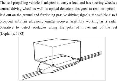
The self-propelling vehicle is adapted to carry a load and has steering-wheels and a central driving-wheel as well as optical detectors designed to read an optical track laid out on the ground and furnishing passive driving signals, the vehicle also being provided with an ultrasonic emitter-receiver assembly working as a radar and operative to detect obstacles along the path of movement of the vehicle. (Deplante, 1982)
Figure 2.2: The diagrammatical perspective view of the AGV adapted to move automatically along an
optically defined path for carrying a load from a starting point to an arrival point. (Deplante, 1982) Hall-effect sensor
Floo Permanent magnet
2.1.3 Self Guided Vehicle
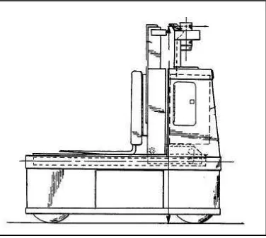
A navigation system for use in a self-guided material handling vehicle provides guidance during operation in areas having densely stacked rows of containers and reduces the potential of deviation of the self-guided vehicle from the desired path travel. A laser-signaling device is mounted on the vehicle and rotatable about an axis of the rotation extending generally perpendicularly to the longitudinal axis of the self-guided vehicle. The laser-signaling device is adapted to delivery a light beam signal at the first preselected angle relative to the axis of rotation of the laser-signaling device, at a second different preselected angle relative to the axis of rotation. Receiving devices a reflection of the light beam signal and delivers a position signal in response to the light beam signal received. The navigation system is particularly suited for use in automation storage and retrieval systems. (Wible, 1990)
Figure 2.3: A diagrammatic side elevation view of a self guided vehicle (Wible, 1990)
2.2 Mechanical Review
2.2.1 Material in Mechanical Design
It needed to specify suitable material for each component of a mechanical device before further designation. The initial efforts in specifying a material for a particular component of a mechanical design should be directed to the basic kind of material to be used. Function of the component, kinds and magnitudes of loads it will carry, and the environment in which it will operate should be specified. (Mott, 2002)
Machine elements are often made from one of the metals or metal alloys such as steel, aluminum, cast iron, zinc, titanium or bronze. Strength, elastic, and ductility properties for metals usually determined and considered in the stage of design.
(a) Carbon and Alloy Steel
Steel is possibly the most widely used material for machine elements because of its properties of high strength, high stiffness, durability and relative ease of fabrication. Many types of steel are available.
The term steel refer to an alloy of iron, carbon, manganese, and one more other significant elements. Carbon has very strong effect on the strength, hardness, and ductility of any steel alloy. The other elements affect hardenability, toughness, corrosion resistance, machinability, and strength retention at high temperature. The primary alloying element present in the various alloy steels are sulfur, phosphorus, silicon, nikel, chromium, molybdenum, and vanadium. (Mott, 2002)
General Form of Designation
The AISI uses a four-digit designation system for carbon and alloy steel as shown above. The first two digits indicate the specific alloy group that indentified the primary alloying element other than carbon in steel. The last two digits indicate the amount of carbon in the steel (Mott, 2002).
Carbon content
Specific alloy in the group Alloy group: indicates major alloying elements