AN AUTONOMOUS VEHICLE USING WALL FOLLOWING DETECTION
MOHD AFFI BIN MOHD ALI
This report is submitted in partial fulfillment of the requirements for the award of Bachelor of Electronic Engineering (Industrial Electronics Engineering) With
Honours
Faculty Of Electronic and Computer Engineering Universiti Teknikal Malaysia Melaka
UNIVERSTI TEKNIKAL MALAYSIA MELAKA
FAKULTI KEJURUTERAAN ELEKTRONIK DAN KEJURUTERAAN KOMPUTER
BORANG PENGESAHAN STATUS LAPORAN
PROJEK SARJANA MUDA II
Tajuk Projek : AN AUTONOMOUS VEHICLE USING WALL FOLLOWING DETECTION
Sesi
Pengajian : 2008/2009
Saya MOHD AFFI BIN MOHD ALI
mengaku membenarkan Laporan Projek Sarjana Muda ini disimpan di Perpustakaan dengan syarat-syarat kegunaan seperti berikut:
1. Laporan adalah hakmilik Universiti Teknikal Malaysia Melaka.
2. Perpustakaan dibenarkan membuat salinan untuk tujuan pengajian sahaja.
3. Perpustakaan dibenarkan membuat salinan laporan ini sebagai bahan pertukaran antara institusi
pengajian tinggi.
4. Sila tandakan ( √ ) :
SULIT*
(Mengandungi maklumat yang berdarjah keselamatan atau kepentingan Malaysia seperti yang termaktub di dalam AKTA RAHSIA RASMI 1972)
TERHAD* (Mengandungi maklumat terhad yang telah ditentukan oleh organisasi/badan di mana penyelidikan dijalankan)
TIDAK TERHAD
Disahkan oleh:
__________________________ ___________________________________
(TANDATANGAN PENULIS) (COP DAN TANDATANGAN PENYELIA)
Alamat Tetap: No 6, Jln 17, Taman Kluang Barat, 86000 Kluang Johor
iii
“I hereby declare that this report is the result of my own work except for quotes as cited in the references.”
Signature :
Supervisor’s Name : Mohd Affi Bin Mohd Ali
Date :
th
iv
“I hereby declare that I had read this report and in my opinion I think this report is sufficient in terms of the scope and quality for the award of Bachelor of Electronic Engineering (Industrial Electronics Engineering) With Honours.”
Signature :
Supervisor’s Name : Puan Norihan Abdul Hamid
Date :
th
v
vi
ACKNOWLEDGEMENT
vii
ABSTRACT
viii
ABSTRAK
ix
CONTENTS
CHAPTER TOPIC PAGE
ABSTRACT vii
ABSTRAK viii
CONTENTS ix
LIST OF TABLES xiii
LIST OF FIGURES xiv
LIST OF ABBREVIATION xvi
LIST OF APPENDIXS xvii
I INTRODUCTION
1.1 Introduction 1
1.2 Project Overview 2
1.3 Project Objectives 4
1.4 Problem Statement 5
1.5 Project Scope 6
1.6 Project Methodology 7
x
II LITERATURE REVIEW
2.1 Overview 10
2.2 Introduction 10
2.3 Theory 12
2.3.1 Electronic Devices 12
2.3.1.1 Ultrasonic Range Finder 13
2.3.2 Motor 14
2.3.2.1 Why Tamiya motor? 15
2.3.3 Microcontroller 16
2.3.3.1 Why Microcontroller? 17
2.4 Component Description 19
2.4.1 Microcontroller- PIC 16F877A 19
2.4.1.1 The PIC16F877A 22
Advantages and Disadvantage
2.4.2 Ultrasonic Sensors 23
2.4.3 L293D IC (Motor Driver) 23
2.4.4 High Speed Gear Motor 24
2.4.5 Power supply 25
2.5 Software 27
2.5.1 Proteus VSM 27
2.5.1.1 Schematics Entry 27
xi
III PROJECT METHODOLOGY
3.1 Introduction 29
3.2 Flow Chart Methodology 29
3.3 General Flow Chart 30
3.4 Flow Chart Description 31
3.4.1 Project Title 31
3.4.2 Information about the Project 31
3.4.2.1 Implementation 33
3.4.3 Project Circuit Design and Testing 33 3.4.3.1 Pattern the Line Current 34
By Using Protues Software
3.4.3.2 Etching the Circuit on the 35 PCB Board
3.4.3.3 Drill the Hole of Component 35 Base on the Board
3.4.3.4 Integrate the Components on 36 the Board
3.4.3.5 Soldering process 36
3.4.4 Combining Final Product 37
3.5 Software Programming 38
xii
IV RESULT AND DISCUSSION
4.1 Introduction 41
4.2 Result and Analysis 41
4.2.1 Hardware Development 44
4.2.2 Software Development 47
4.3 Discussion 48
V CONCLUSION AND RECOMMENDATION
5.1 Introduction 50
5.2 Conclusion 50
5.3 Recommendation 51
REFERENCES 52
xiii
LIST OF TABLES
NO TITLE PAGE
2.1 Comparison between Stepper Motor and DC Motor 14
2.2 Types of Microcontroller 18
xiv
LIST OF FIGURES
NO TITLE PAGE
1.1 The Block Diagram of Autonomous Vehicle 3
1.2 Overall Project Flow 7
2.1 Ranging Measurement for Ultrasonic Sensor 13
2.2 Tamiya FA-130 motor 15
2.3 The PIC 16F877A 19
2.4 The Ultrasonic Sensor 23
2.5 L293D IC 24
2.6 High Speed Gear Motor 25
2.7 78L05 +5V Positive Voltage Regulator IC 25
2.8 LM 78L05 26
3.1 Project Flow Chart 30
3.2 The Basic Flow Chart of a Working Robot 32
3.3 The Flow Process of Project Circuit Design 33
3.4 IR Sensor Circuit 34
3.5 Motor and PIC Circuit 34
3.6 IR Sensor Circuit 35
3.7 Motor and PIC Circuit 35
3.8 The Board after Drilling Process 35
3.9 PIC and Motor Circuit 36
3.10 IR Sensor Circuit 36
xv
3.12 The Complete Prototype of Wall Following Robot 37 3.13 The Autonomous Vehicle using Wall Following Detection 37
3.14 Top and Bottom Layer Drawing of Robot 39
3.15 The Real Shape of Wall Following Robot 40
3.16 The Standoffs is installed to the Plastic Sheet 40
4.1 Interface Circuit 42
4.2 The motor movement after switch ON the switch 42
4.3 The Sensor Circuit 44
4.4 The IR Sensor Circuit 45
4.5 The H Bridge Circuit 46
4.6 Motor Circuit 46
xvi
LIST OF ABBREVIATION
DC - Direct Current
EMI - Electromagnetic Interface CD - Compact Disc
DVD - Digital Video Disc 4WD - 4 Wheel Drive
RPM - Revolutions per Minute RAM - Random–Access Memory I/O - Input / Output
ROM - Read-Only Memory
ADC - Analog to Digital Converter
EEPROM- Electrically Erasable Programmable Read-Only Memory A/D - Analog to Digital
D/A - Digital to Analog ICD - In-Circuit Debugger CCP - Capture – Compare
UART - Universal Asynchronous Receiver/ Transmitter PSP - Parallel Slave Port
LV - Low Voltage
LCD - Liquid Crystal Display PCB - Printed Circuit Board PVC - Polyvinyl Chloride
xvii
LIST OF APPENDIXS
NO TITLE PAGE
A DATASHEET OF BD135 54
B DATASHEET OF TAMIYA MOTOR 58
C DATASHEET OF L293D 59
CHAPTER I
INTRODUCTION
1.1 Introduction
2
1.2 Project Overview
An autonomous wall following detection is a vehicle that has capability of traveling and stopping parallel to a wall includes right and left driving wheels. In the other word, this autonomous vehicle system will follow a pre-determined path marked by stationary beacons and the control system is built to control the actuation and motor system for the autonomous vehicle system.
The medium used for this autonomous vehicle are a dependent wheel for supporting the autonomous vehicle together with the driving wheels for a straightforward movement and a U-turn, a motor for driving the right and left driving wheels, a distance measurement sensor for measuring the distance to a right or left object of interest, and a controller for controlling the autonomous vehicle through the motor and the driving wheels [1].
3
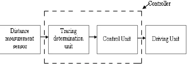
Figure 1.1 The Block Diagram of Autonomous Vehicle
As the block diagram above, it is divided into 3 sections which are the input, controller and output. The distance measurement sensor is used as an input, the tracing determination unit and control unit which have in the PIC chip is a controller. Other than that, the output component of this project is a driving unit.
4
1.3 Project Objectives
The objectives of this project are as follows:
i. To study how to built the robot that using the wall as a path away.
ii. To implement the PIC 16F877 programming for this autonomous vehicle.
iii. To study the basic of PIC programming in order to understand how to develop it in the proper sequence.
5
1.4 Problem Statement
The invention results from the realization that a low cost, accurate, and easy to implement system for either preventing an autonomous porter robot from driving off a stair or over an obstacle which is too high or too low and/or for more smoothly causing the robot to follow a wall for more thorough carrying can be effected by intersecting the field of view of a detector with the field of emission of a directed beam at a predetermined region and then detecting whether the obstacles or wall occupies that region.
Besides, it is a further object of this invention to provide a sensor subsystem for a robot which consumes a minimal amount of power and unaffected by surfaces of different reflectivity.
6
1.5 Project Scope
The scopes of this project are to study about PIC 16F877, a suitable sensor or wall sensor and wall following robot system. After research, the type of a wall sensor, type of motor and the circuit design for the system will be conclude.
A sensor that is choosing for this robot is an IR sensor. It is because the low cost and good specification of this sensor can make a detection process is much better. The PIC 16F877 is a chip that stored the developed programming into it. The developed programming is created in the PIC C Compiler software by using the C language in order to give the instruction to the output of this vehicle which is the driving motor to follow the wall as the path away.
7
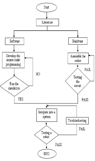
[image:24.595.153.465.157.684.2]1.6 Project Methodology
Figure 1.2 shows the process flow throughout the project.