AERODYNAMICS COOLING OF DISC BRAKE ROTOR
MOHD RAUS BIN ZAINUDIN
‘I admit that have read this work and in my opinion this work was adequate from the aspect scope and quality to award Ijazah Sarjana Muda Kejuruteran Mekanikal
(Termal-Bendalir)
Signature :……….
Supervisor :……….
AERODYNAMICS COOLING OF DISC BRAKE ROTOR
MOHD RAUS BIN ZAINUDIN
This dissertation is submitted as partial fulfillment of the requirement for the degree of
Bachelor of Mechanical Engineering (Thermal Fluid)
Fakulti Kejuruteraan Mekanikal Universiti Teknikal Malaysia Melaka
“I declare that this report is done by my own exclude citation with the mentioned references for each.”
iii
ACKNOWLEDGEMENT
I would like to thank my supervisor Mr. Mohd Zaid bin Akop for his helps and encouragements that he has given during completion of this Projek Sarjana Muda.
Cooperation from my friends Hadi, Muhammad and Syahrom is also appreciated for giving assistance to understand the concept of simulation in CFD.
v
ABSTRAK
ABSTRACT
vii
CONTENTS
CHAPTER ITEMS PAGE
DECLARATION ii
DEDICATION iii
ACKNOWLEDGEMENT iv
ABSTRAK v
ABSTRACT vi
CONTENTS vii
LISTS OF TABLES ix
LISTS OF FIGURES x
LISTS OF SYMBOLS xiii
LISTS OF APPENDICES xiv
CHAPTER 1 INTRODUCTION 1
1.1 Background of project 1
1.2 Significant of project 2
1.3 Objectives 2
1.4 Scope of project 2
1.5 Problems statement 3
CHAPTER 2 LITERATURE REVIEW 4
2.1 Overview of disc brake 4
2.2 Friction Braking System 5
2.3 Types of Friction Braking Systems 5
2.4 Brake Fluid Vaporization 6
2.5 Brake Fade 6
2.7 Dissipation of Heat from Disc Brakes
7
2.8 Vehicle Aerodynamics 9
2.9 Computational Fluid Dynamics 10
2.10 Aerodynamics and brake cooling 11 2.11 Aerodynamic of ventilated brake
disc
12
CHAPTER 3 PROJECT METHODOLOGY
3.1 Introduction 13
3.2 Materials 14
3.3 CFD at a glance 15
3.4 Applied methodology for isothermal simulation
16
3.5 The model geometry and boundary condition
19
CHAPTER 4 RESULTS 24
CHAPTER 5 DISCUSSION 44
CHAPTER 6 CONCLUSION 47
REFERENCES 48
BIBLIOGRAPHY 50
ix
LIST OF TABLES
NO. TITLES PAGE
4.1 Air mass flow pumped through channel 25
LISTS OF FIGURES
NO. TITLES PAGE
2.1 Picture of a failed front brakes disc rotor (T.J. Mackin et al, 2000)
4
2.2 Schematic view of drum and disc brakes (Baker A.K., 1986)
6
3.2.1 Front view of Straight vane rotor 15
3.2.2 Front view of Circular pillar rotor 15
3.2.3 Front view of Solid rotor 15
3.3 Numerical domain for the Straight Vanes rotor
17
3.4 Location of the internal annular heat sources adapted from (Wallis M.L., 2003)
18
3.5 Mesh of Straight Vane rotor 20
3.6 Mesh of Circular Pillar rotor 21
3.7 Mesh of Solid rotor 21
3.8 Solver 22
3.9 Operating Condition 22
3.10-3.12 Boundary Condition 23
4.1 Contour of velocity magnitude of air (m/s) for SV rotor on 100 rad/s
26
4.2 Contour of velocity magnitude of air (m/s) for CP rotor on 100 rad/s
27
4.3 Contour of velocity magnitude of air (m/s) for Solid rotor on 100 rad/s
27
xi SV rotor on 180 rad/s
4.5 Contour of velocity magnitude of air (m/s) for CP rotor on 180 rad/s
28
4.6 Contour of velocity magnitude of air (m/s) for Solid rotor on 180 rad/s
29
4.7 Contour of velocity magnitude of air (m/s) for SV rotor on 220 rad/s
30
4.8 Contour of velocity magnitude of air (m/s) for CP rotor on 220 rad/s
30
4.9 Contour of velocity magnitude of air (m/s) for solid rotor on 220 rad/s
31
4.10 Contour of static temperature (K) for SV rotor on 100 rad/s
32
4.11 Contour of static temperature (K) for CP rotor on 100 rad/s
32
4.12 Contour of static temperature (K) for Solid rotor on 100 rad/s
33
4.13 Contour of static temperature (K) for SV rotor on 180 rad/s
34
4.14 Contour of static temperature (K) for CP rotor on 180 rad/s
34
4.15 Contour of static temperature (K) for Solid rotor on 180 rad/s
35
4.16 Contour of static temperature (K) for SV rotor on 220 rad/s
36
4.17 Contour of static temperature (K) for CP rotor on 220 rad/s
36
4.18 Contour of static temperature (K) for Solid rotor on 220 rad/s
37
4.19 Graph of mass flow versus rotational velocity for SV rotor
38
4.20 Graph of mass flow versus rotational velocity for CP rotor
4.21 Graph of mass flow versus rotational velocity for Solid rotor
40
4.22 Graph of convective heat transfer versus rotational velocity for SV rotor
41
4.23 Graph of convective heat transfer versus rotational velocity for CP rotor
42
4.24 Graph of convective heat transfer versus rotational velocity for Solid rotor
43
4.25 Graph of passage heat transfer coefficient versus speed (rad/s) for validation
xiii
LIST OF SYMBOLS
µ = Coulomb friction
M = Mass
V = Velocity
t = Time, s
r = Radius
Q = Rate of heat transfer ,Watts(W)
h = Convection heat transfer coefficient (W/m2 k)
A = Area
T = Temperature
D = Aerodynamic Drag
ρ = Density
Cd = Non-dimensional Drag Co-efficient
Z = Number of vanes
D = The mid diameter of the rotor
w = The flow passage width
t = Thickness of the vanes
ω = Rotational velocity (rad/s) Reff = Effective radius (m) ad = Deceleration rate (rad/s2) I = Brake rotor inertia (kg/m2) E = Total braking energy (kJ)
q = Heat flux ( kW/m2)
LISTS OF APPENDICES
NO. TITLES PAGE
A Relationship between brake rotor rotational velocity and external air-stream.
53
B Conversion of Rotor Angular Speed to Vehicle Linear Speed
54
1
CHAPTER 1
INTRODUCTION
1.1 Background of project
The braking system is undeniably the most important parts in a road vehicle. It must be able to remove the kinetic and potential energy of the vehicle to enable safe retardation. Friction brakes operate by converting vehicles kinetic and potential energy into thermal energy (heat). According to (Limpert, 1975), during braking a large amount of heat can be created and has to be absorbed by brake components in every short space of time. However the allowable temperatures of the brake and surrounding components limits the thermal energy a brake can store. According to (Day and Newcomb, 1984) the absorb heat must be effectively dissipated to achieve satisfactory performance of braking. According to (Day, 1988) high temperatures are responsible for most problems in vehicle braking system. If the heat is not dissipated effectively the temperature in the brake and surrounding components become too high. This circumstance will lead to excessive component wear, squeal and complete failure of the brakes. To reduce the problems and to create safer vehicles transport, the improvement to the cooling characteristics of braking system is extremely needed.
and must be directed to the appropriate region since airflow or cooling air give major assist to convection heat transfer.
1.2 Significant of project
The significant of this project is to provide better understanding of aerodynamics brake cooling. The purpose of this project is also to recommend methods of improving aerodynamics heat dissipation. The result of the project will serve information onto aerodynamics improvement that can be made to automotive brake cooling. By improving brake cooling, the weight of the brake and associated component maybe reduced. The thermal brake failure (brake fade and fluid vaporization) also can be reduced as well as noise and cost.
1.3 Objectives
The objectives of this project are:
• To understand the working principles, components, standard and theories through a literature studies
• To understand the working principles of CFD software (FLUENT 6.1) • To understand the fundamental of heat transfer through airflow of disc
brake rotor
• To study the airflow of disc brake rotor and provide the cooling effect through heat transfer.
3
1.4 Scope of project
This study is primarily focus on:
a) Literature review on the working principles, components, standard and theories.
b) Construction of 3D model of disc brake rotor.
b) To do an analysis with the disc brake rotor using Computational Fluid Dynamics (CFD).
c) Final justification and conclusion.
1.5 Problems statement
CHAPTER 2
LITERATURE REVIEW
2.1 Overview of disc brake
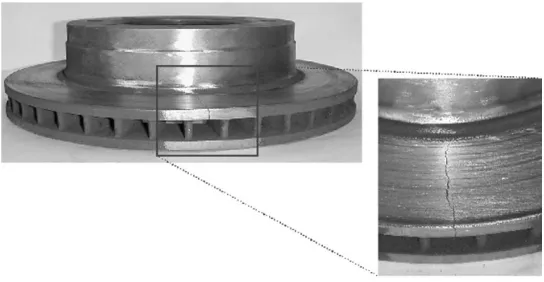
[image:20.595.155.427.507.648.2]Large thermal stresses always occurred during routine braking and larger thermal stresses happened during hard braking. Typical passengers vehicle can generate as high as 900°C which may produce two possible outcome that are surface crack or large amount of plastic deformation. T.J. Mackin et al.(2000) had studied on thermal cracking that happens in disc brakes. Their findings said that the cracks fall into two categories: a series of heat cracks that partially penetratre the surface of the disc and thru cracks that completely pass through the disc wall.
Figure 2.1 Picture of a failed front brakes disc rotor (Source: T.J. Mackin et al, (2000))
5
unit to eliminate constraint stresses. New brake materials have been identified that can operate at higher temperature but this leads to a need for heat shielding around the brakes. Designs that incorporate cooling also difficult to achieve. The best way is to eliminate constraint brought about by rotor-hub.
2.2 Friction Braking Systems
Friction brakes happen by converting the vehicles kinetic, and sometimes potential energy into thermal energy (heat). Heat is created due to friction at the interface between a rotor (disc or drum) and (pads or shoes). During braking, a large amount of heat can be created and has to be absorbed by the rotor. The rotor and surrounding components effectively act as temporary thermal storage devices, and sufficient cooling of these components is essential to achieve satisfactory performance of the braking system, (Day and Newcomb, 1984). It is therefore vital that heat is effectively dissipated for the successful operation of a braking system.
2.3 Types of Friction Braking Systems
Figure 2.2: Schematic view of drum and disc brakes, (Source: Baker A.K., 1986) The disc brake gain broad advantages against drum brakes in passenger’s cars and light duty truck.
The advantages of disc brakes are:
a. The rubbing surfaces that contact with disc brakes are exposed to the atmosphere resulting better cooling and minimizing the possibility of thermal failure.
b. Disc brake adjustment is achieved automatically while for drum brake adjustment can be achieved only when frictional material wears.
c. Disc brakes are less sensitive to high temperatures and can operate safely at temperatures of up to 1000°C. Drum brakes due to their geometry and effects on their friction co-efficient should not exceed 500-600°C, (Limpert, 1999). Brake discs (solid and vented) are generally cast from an iron alloy and machined to the required finish.
2.4 Brake Fluid Vaporization
7
then form in the hydraulic circuit, and as gas is more compressible than liquid the pedal stroke is used to compress this gas without actuating the brakes. Brake fluid is hydroscopic causing it to absorb water from the atmosphere over time; this may result in a reduced boiling temperature of the fluid, (Hunter et al., 1998). Therefore it is usually recommended by vehicle manufacturers to replace brake fluid periodically.
2.5 Brake Fade
Brake fade is a temporary loss of braking that occurs as a result of very high temperatures in the friction material. The high temperature reduces the coefficient of friction between the friction material and the rotor, and results in reduced braking effectiveness and ultimately failure. Generally fade is designed to occur at temperatures lower than the flame temperature of the friction material to reduce the possibility of fire at extreme temperatures. Normal braking will usually return when temperatures drop below their critical level.
2.6 Excessive Component Wear
2.7 Dissipation of Heat from Disc Brakes
The rise in temperature of the brake disc in any braking operation will depend on a number of factors including the mass of the vehicle, the rate of retardation, and the duration of the braking event. In the case of short duration brake applications with low retardation, the rotor and friction material may absorb all of the thermal energy generated.
As a result very little heat dissipation occurs as the temperature rise in the rotor is minimal. In extreme braking operations such as steep descents or repeated high speed brake applications, sufficient heat dissipation becomes critical to ensure reliable continued braking. As the rotor temperature rises it begins to dissipate heat, at steady-state conditions heat generated through braking equals heat dissipation and no further heating occurs. If the heat generation is greater than the dissipation then the temperature will rise, the rate of this rise value will depend of the relative quantities of each. If sufficient heat dissipation does not occur the temperature of the rotor and friction material can reach critical levels and brake failure may occur.