UNIVERSITI TEKNIKAL MALAYSIA MELAKA
DESIGN, SIMULATION AND ANALYSIS OF DISC ROTOR USING
ANYCASTING SOFTWARE
This report submitted in accordance with requirement of the Universiti Teknikal Malaysia Melaka (UTeM) for the Bachelor's Degree in Manufacturing Engineering
Technology (Product Design) (Hons.)
by
NORAZIRA BINTI JANI B071210443
900129-14-5440
DECLARATION
I hereby, declare that this report entitled “Design, Simulation, and Analysis of Disc Rotor Using Anycasting Software” is the result of my own research except as cited in the references.
Signature : ………. Name : NORAZIRA BINTI JANI
APPROVAL
This report is submitted to the Faculty of Engineering Technology of UTeM as a partial fulfillment of the requirements for the degree of Bachelor of Engineering Technology Product Design (Hons.). The member of the supervisory is as follow:
………. (Project Supervisor)
ABSTRAK
Tujuan kajian ini adalah untuk mengkaji tentang kecacatan yang akan terhasil
dalam proses tuangan pada cakera brek daripada bahan 'gray cast iron' melalui proses
tuangan pasir. Kajian ini mengenai tuangan pasir dalam menghasilkan produk dimana di
dalam industri pembuatan setiap produk yang dihasilkan mestilah mengikut spesifikasi
dan kualiti yang ditentukan bagi mengelakkan produk itu tidak diterima. Pendekatan cuba
jaya digantikan dengan teknologi moden dimana perisian simulasi digunakan dalam
industri tuangan. Perisian Solidwork digunakan dalam memodel produk dan perisian
simulasi AnyCasting digunakan dalam menjalankan proses tuangan pasir. Empat sifat
kualiti yang akan dikaji iaitu masa pembekuan, rongga susut, mikro porositi dan isipadu
penahan cairan. Hasil daripada ujikaji yang telah dilakukan, masa tuangan 100% kadar
tuangan untuk rekabentuk 1 ialah 5.9865 saat, untuk rekabentuk 2 ialah 7.6648 saat dan
untuk rekabentuk 3 sebanyak 1.5559 saat. Masa pembekuan pada 100% kadar pembekuan
untuk rekabentuk 1 ialah 1172.8 saat, rekabentuk 2 selama 1452.6 saat dan rekabentuk 3
ABSTRACT
DEDICATION
ACKNOWLEDGEMENT
First of all, I would like to thank to Allah because without HIM I was lost and nothing in this world. I would like to express my deepest appreciation to all those who provided me the possibility to complete this Final Year Project report. I am highly indebted to Ms. Nur Farah Bazilah binti Wakhi Anuar and Mr. Mohamad Ridzuan bin Mohamad Kamal for their valuable guidance and advice and also constant supervision as well as for providing necessary information regarding the project and also for their support in completing this project.
I would like to express my gratitude toward my father, Jani bin Isa and my mother, Mardiah binti Gariman because of their understanding, supporting and also for their encouragement which help me from the beginning until now in completion of this project.
LIST OF TABLES
Table 2.1 Graphitization Range of Composition of Gray Iron
Table 3.1 Typical Value of Volumetric Shrinkage
Table 4.1 The Filling Time for All 3 Designs
Table 4.2 Filling Time Result AnySOLVER for Design 1 Table 4.3 Filling Time Result AnySOLVER for Design 2 Table 4.4 Filling Time Result AnySOLVER for Design 3 Table 4.5 The solidification Time for All 3 Designs
Table 4.6 Solidification Time Result AnySOLVER for Design 1 Table 4.7 Solidification Time Result AnySOLVER for Design 2 Table 4.8 Solidification Time Result AnySOLVER for Design 3 Table 4.9 The Value Set on Heat Transfer Model
LIST OF FIGURES
Figure 2.1 The Changes Occur on Cooling in Hypoeutectic White Cast Iron. Figure 2.2 Microstructure of White Cast Iron.
Figure 2.3 Microstructure of Gray Cast Iron. Figure 2.4 Microstructure of Malleable Cast Iron. Figure 2.5 Microstructure of Ductile Cast Iron. Figure 2.6 Sand Casting Process.
Figure 2.7 Solid Pattern. Figure 2.8 Split Pattern.
Figure 2.9 Match-Plate Pattern. Figure 2.10 Cope and Drag Pattern. Figure 2.11 The Gating System element. Figure 2.12 Typical Shape of Pouring Basin. Figure 2.13 Top Gate.
Figure 2.18 Porosity Defect.
Figure 2.19 The Inclusion of Foreign Material. Figure 2.20 Mould Shift Defect.
Figure 2.21 Misruns Defect. Figure 2.22 Penetration Defect.
Figure 3.1 Process Flow for Both Bachelor Degree Project 1 and 2. Figure 3.2 The Real Part of Disc Brake.
Figure 3.3 Disc Brake Part Drawing.
Figure 3.4 (a) The head of metal varies from H at the start of pour to h at the end. M is; (b) √h for a top gated system; (c) √(h-c/2) for a bottom gated system; (d) √(h-p2/2c) for a side gated system
Figure 3.5 Experimental Flow Chart Figure 3.6 AnyPRE Process Flow Figure 3.7 AnyPRE Feature
Figure 3.8 The Setting for The Gate Condition Figure 3.9 The AnySOLVER
Figure 3.10 AnySOLVER Complete Figure 3.11 AnyPOST Feature
Figure 4.2 Design 2 Figure 4.3 Design 3
Figure 4.4 Analysis of Filling Time on Design 1 Figure 4.5 Analysis of Filling Time on design 2 Figure 4.6 Analysis of Filing Time on Design 3
Figure 4.7 Analysis of Solidification Time on Design 1 Figure 4.8 Analysis of Solidification Time on Design 2 Figure 4.9 Analysis of Solidification Time on Design 3 Figure 4.10 Analysis of Retained Melt Volume for design 1 Figure 4.11 Analysis of Retained Melt Volume for Design 2 Figure 4.12 Analysis of Retained Melt Volume for Design 3 Figure 4.13 Analysis of Particle Tracing for Design 1 Figure 4.14 Analysis of Particle Tracing for Design 2 Figure 4.15 Analysis of particle Tracing for Design 3
Figure 4.16 Analysis of Macro Shrinkage on Probabilistic Defect Parameter for the Design 1
Figure 4.17 Analysis of Macro Shrinkage on Probabilistic Defect Parameter for the Design 2
Figure 4.18 Analysis of Macro Shrinkage on Probabilistic Defect Parameter for the Design 3
LIST OF ABBREVIATIONS, SYMBOLS AND
NOMENCLATURE
C - Carbon
CAD - Computer Aided Design
Fe - Iron
FeCr2O4 - Chromite Fe2SiO4 - Fayalite Mg2SiO4 - Fosterite
Mn - Manganese
P - Phosphorus
S.G - Spheroidal Graphite
S - Sulphur
Si - Silicon
INTRODUCTION
1.1 Background
Foundry sand is often used in the industry to make parts consisting of iron, bronze, copper and aluminum as well. The metal is poured into the mould cavity that formed by the sand when the metal melted in the furnace. The process is relatively simple and inexpensive, and many industries use this process. However, the weakness of sand casting is commonly in parts of cast sand and it can affect the properties of casting materials (Merten, 2012).
Gray cast iron is one of the most important casting materials and has many industrial applications because of its good castability properties and large variation in mechanical properties. The variation of mechanical properties depends on the microstructure. The quality of the casting parts is depend on the percentage of the porosity in the product (Kumar & Kumar, 2012).
proper running and gating system is the most importance to take into account to solve this problems. However, the translucent of the mould and high temperature molten metal during the casting process makes it difficult to be observed. Trial and error practices to get optimum design are expensive and time consuming. Casting process simulation is to help engineers to optimize the design foundry through a better understanding of the history of the solidified casting temperature. Simulation results can be used to obtain a defect free casting a systematic way (Yeh, Hwang, & Lin, 2008).
1.2 Problem Statement
The major problem in casting was defect. To detect the defect in the casting are by using a simulation because it is more simple and easy to detect the problem. In this simulation, we can know the problem about the solidification defect in casting. It is because, by using this simulation, we can see in three dimensional views. From that, we can see clearly at which part the defect on the cast occurs. In this project the result were simulate by the AnyCasting software. AnyCasting software simulation designed for casting process. It will help the foundry to produce better casting with forecast the defect through a simulation.
1.3 Objectives
The objectives of this project are:
i. To design the mould sand casting using Solidworks.
ii. To simulate the casting simulation of Gray Cast Iron disc brake in AnyCasting software.
This project will be limited to this aspect:
i. This project is focusing on the defects of gray cast iron disc brake.
ii. This project also focusing on the defect casting parameter in AnyCasting software.
CHAPTER 2
LITERATURE REVIEW
2.1 Introduction
Most brake rotor was made from gray cast iron is produced by many industrial foundry in this era. The cast iron material vary from the steel materials were higher in carbon (C) content and silicon (Si). Heavy steel have weight less than 1.2 percent (wt.%) carbon and a little or no silicon, where the carbon content in a cast iron usually range from 2.5 to 4.5 wt.% C and 1 to 3 wt.5 Si. It have a higher Sulphur (S) and Phosphorus (P) contents meanwhile the manganese is an important additive in the both metals. To lower the melting point of the metal, it must be added some extra carbon and silicon in cast iron. Cast iron material is easy to cast the complex shapes such as fittings and pipe. It will tend to form a brittle iron sulphide at the boundaries of the grains if it is without the Manganese even it is with Sulphur. This will cause the inclusion form and cause the crack during rolling and other forming and it would be a problem in steels (Iraqi, For, & Engineering, 2010).
2.2 Cast iron
manufacture itself will affect and the composition of the cast iron are must be taken very seriously.
Cast iron is commonly used in variety of structural and a decorative application because of it is reasonably inexpensive, durable and easy to cast into several of shapes and the most typical that are used:
i. Hardware such as hinges, latches ii. Stairs
iii. Fences
iv. Tools and utensils v. Stoves
vi. Structural connectors in buildings and monuments.
The characteristic of cast iron is extremely strong and durable when it is used correctly and confined from adverse exposure. It is commonly found in columns, rather than in structural beams because of, it is much stronger in compression than in tension. However, it is disposed to corrosion when it is exposed to moisture and has several regular problems which usually can be identified by visual inspection (Pulkit Bajaj, 2010).
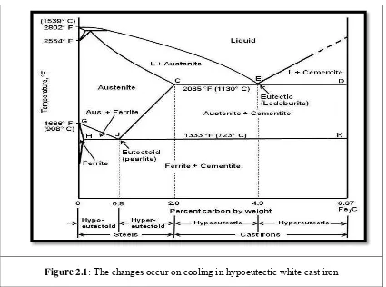
2.2.1 White cast iron
Figure 2.1: The changes occur on cooling in hypoeutectic white cast iron
The typical microstructure of white cast ironis consisting of dendrites of changed of austenite (Pearlite) in a white interdendritic network of cementite as shown in Figure 2.2 below.
Figure 2.2: Microstructure of white cast iron