KOLEJ UNIVERSITI TEKNIKAL KEBANGSAAN
MALAYSIA
Design and Analysis of Manufacturing System
Using Simulation
Thesis submitted in accordance with the requirements of the National Technical University College of Malaysia for the Degree of Bachelor of Manufacturing Engineering (Honours) (Manufacturing Process)
By
KUTKM Library (Pind.1/2005)
JUDUL: DESIGN AND ANALYSIS OF MANUFACTURING SYSTEM USING SIMULATION
SESI PENGAJIAN : 2/ 2005-2006
Saya _____________________________________________________________________
mengaku membenarkan t esis (PSM/ Sarj ana/ Dokt or Falsaf ah) ini disimpan di Perpust akaan Kolej Universit i Teknikal Kebangsaan Malaysia (KUTKM) dengan syarat -syarat kegunaan sepert i berikut :
1. Tesis adalah hak milik Kolej Universit i Teknikal Kebangsaan Malaysia. 2. Perpust akaan Kolej Universit i Teknikal Kebangsaan Malaysia dibenarkan
membuat salinan unt uk t uj uan pengaj ian sahaj a.
3. Perpust akaan dibenarkan membuat salinan t esis ini sebagai bahan pert ukaran ant ara inst it usi pengaj ian t inggi.
4. **Sila t andakan (√)
MOHD RAJHAN BIN SAID
KOLEJ UNIVERSITI TEKNIKAL KEBANGSAAN MALAYSIA
BORANG PENGESAHAN ST AT US T ESIS*
Disahkan ol eh:
(TANDATANGAN PENULIS)
Alamat Tet ap:
No. 44, Lorong 3, Tmn Sri Selama, 34100, Selama,
Perak Darul Ridzuan.
Tarikh: _______________________
(TANDATANGAN PENYELIA)
Cop Rasmi:
Tarikh: _______________________
* Tesis dimaksudkan sebagai t esis bagi Ij azah Dokt or Falsaf ah dan Sarj ana secara penyelidikan, at au
(Mengandungi maklumat TERHAD yang t elah dit ent ukan oleh organisasi/ badan di mana penyelidikan dij alankan) (Mengandungi maklumat yang berdarj ah keselamat an at au kepent ingan Mal aysia yang t ermakt ub di dalam AKTA RAHSIA RASMI 1972)
TIDAK TERHAD
√
DECLARATION
I hereby, declare this thesis entitled “Design and Analysis of
Manufacturing System Using Simulation” is the results of my own research except as cited in the reference.
Signature : ………
APPROVAL
This thesis submitted to the senate of KUTKM and has been accepted as fulfillment of the requirement for the Bachelor of Manufacturing Engineering (manufacturing
Process) (Honours). The members of the supervisory committee are as follows:
……… Main supervisor
ABSTRACT
DEDICATION
For my beloved parents, Said bin Tasu and Rapiah binti Abdullah To my supervisor, Prof. Dr. Mohd Razali bin Muhamad
ACKNOWLEDGEMENT
ِﻢْﻴِﺣ
ﱠﺮﻟا
ِﻦٰﻤْﺣ
ﱠﺮﻟا
ِﷲا
ِﻢْﺴِﺑ
Firstly, thanks a lot to Allah s.w.t because of given me a spirit and chance to finish my thesis on time. I would like to thank my parent for given me a moral support, motivation and also in financial support by preparing equipment in the likes of computer and other expense. I would also like dedicate all my friends in which playing a major role of this success. Not forget to my lecturer, Assoc. Prof. Chong Kuan Eng of given me a research project from industry. Thank you to him because expend his time to guide and teach me to solve a research problems.
TABLE OF CONTENTS
Abstract……….. i
Dedication………..ii
Acknowledgement……….iii
Table of Contents………...…...iv
List of Figures………...…...xii
List of Tables………..….xiii
CHAPTER 1: INTRODUCTION 1.1 INTRODUCTION………...…. 1
1.2 PROBLEM STATEMENT……….…..4
1.3 OBJECTIVES………...5
1.3 SCOPE OF PROJECT………..5
CHAPTER 2: LITERATURE REVIEW 2.1 MANUFACTURING SYSTEM……….6
2.1.2 Manufacturing System Classification……….……9
2.1.2.1Type I: Single Station……….10
2.1.2.2Type II: Multi Station Cell……….10
2.1.2.3Type III: Production Lines……….10
2.1.3 Characteristic of Manufacturing System………....10
2.1.4 Manufacturing Terminology………...11
2.2 MODELING A MANUFACTURING SYSTEM...13
2.2.1 Manufacturing Modeling Technique………..….13
2.2.2 Use Simulation of Manufacturing………...17
2.2.3 Advantages of Simulation………... 19
2.2.4 Types of Simulation……… 21
2.2.5 Discrete of Simulation………. 22
2.2.6 Discrete Event vs. Continuous Simulation………...25
2.3 ASSEMBLY LINE BALANCING………..27
2.3.1 Assembly Line………..27
2.3.2 Modeling a Assembly Line……….……….……....27
2.4 SIMULATION TOOL: WITNESS………...29
CHAPTER 3: METHODOLOGY 3.1 INTRODUCTION………...….31
3.3 TOOLS………...…………...……….34
3.3.1 Data Collection………...………...34
3.3.2 Data Storage………...………..35
3.3.3 Simulation Software: WITNESS………..…………...35
3.4 EXECUTION………...………....37
3.4.1 Optimization……….38
3.4.2 Project Planning………...………39
CHAPTER 4: DATA COLLECTION 4.1 INTRODUCTION………..…..40
4.2 COMPANY BACKGROUND………...40
4.3 PRODUCTION PROCESS………..……….…...…41
4.4 ASSEMBLY LINE………..………...…..41
4.4.1 Current Layout……….………..…..………42
4.4.2 Current Task Time and Station………..….……….43
4.5 PROJECT ACTIVITIES………..………44
4.5.1 Observation……….………...44
4.5.2 Parameter Collection……….…...…45
4.5.3 Assembly Line Balancing………....46
4.5.4 COMSOAL Approach………..46
4.5.6 COMSOAL Advantages………...47
4.5 ANALYSIS……….….48
CHAPTER 5: SIMULATION MODEL DEVELOPMENT 5.1 INTRODUCTION………….………...49
5.2 MODEL DEFINATION……….……….….…49
5.2.1 Part………..……….….50
5.2.2 Buffer………..……….….51
5.2.3 Machine………..……….….52
5.2.4 Labor………..………..…53
5.2.5 Variable………..………..54
5.3 MODEL DEVELOPMENT………..……….……..55
5.3.1 Beginning of Simulation Modeling………..……….…...55
5.3.2 Assumption………..………...56
5.4 STRUCTURAL MODEL………..………..57
5.5 VERIFICATION……….……….…...57
5.6 VALIDATION……….………....………59
5.8 RUN TIME………...61
5.9 SIMULATION MODEL……….….61
CHAPTER 6: OPTIMIZATION 6.1 INTRODUCTION……….………….….………62
6.2 DESIGN DESCRIPTION………..………….….62
6.2.1 Problems………..………....63
6.2.2 Solution………..…………..…63
6.2.3 COMSOAL result sequence………..….…..65
6.2.4 Erase the Bottleneck………...………..…67
6.3 DESIGN LIMITATION………..….……...….70
6.3.1 Zoning Constraint………...………….….70
6.3.2 Technological Constraint………..….……..71
6.3.3 Parallel………..……….….……..71
CHAPTER 7: RESULTS 7.1 INTRODUCTION………...…….……72
7.2 RESULTS FOR CURRENT LAYOUT………..….72
7.2.2 VMI 1 Utilization………..…...74
7.2.3 T3AB Utilization……….………..…...76
7.2.4 T3C Utilization……….………..…..77
7.2.5 T3D Utilization………...…..78
7.2.6 VMI 2B………,,,………..…79
7.3 RESULT FOR NEW LAYOUT………..………….80
7.2.1 Productivity for a week………...…….80
7.2.2 VMI 1 Utilization………..…….…………...…...81
7.2.3 T3AB Utilization………...83
7.2.4 T3C Utilization………...…..84
7.2.5 T3D Utilization………...…..85
7.2.6 VMI 2B………...…..86
CHAPTER 8: DISCUSSION & CONCLUSION 8.1 Discussion………...….87
8.2 Constraint………...…87
8.3 Overall……….…...….88
8.4 Conclusion……….……..91
APPENDICES
LIST OF FIGURES
2.1 The position of the manufacturing………...……….7
system in the larger production system 2.2 Types of routing in multiple station manufacturing systems: (a) Variable routing and (b) Fixed routing………...…..8
2.3 Modeling Transfer Machine ………..……….………….15
2.4 Continuous Flow System ……….…………16
2.5 Quantity of flow when: a) rate is constant, b) rate is changing……..….……… 16
2.6 Flow Chart of How Discrete Event Simulation Work ….……….……. 24
2.7 Discrete Event cause Discrete State Change………..………. 26
2.8 Comparison of Discrete Change State Variable and Continuous Change State Variable………...……….……26
3.1 The iterative process of simulation model development.……….………33
3.2 Example of stopwatch……….…...34
3.3 Run Time Toolbar; capable……….……...35
3.4 Push and Pull concept between elements………...36
3.5 Setup the elements (e.g.: Machine) ……….….…...36
3.6 Research Planning Flow Chart……….39
4.1 Current Assembly Line Layout………....42
5.1 Parts exist in the assembly line (in simulation layout)……….…50
5.2 PlasticWindowtray, PCBtray, and MetalChassisTray………...51
5.6 Labor (Machine Modifying)………..…...52
5.7 Ultra Sonic Welding Machine………..……53
5.8 Pressing Jig………..….…....53
5.9 Computer for T3AB – Programming ……….……...…....53
5.10 Connection between the stations in simulation………..…..…56
5.11 Input same as Output……….….……….….58
5.12 Tolerance Graph for Validation………...…….59
6.1 Current Assembly Line Precedence Structure………..…………....64
6.2 Bottleneck……….………....68
7.1 VMI 1 utilization for one week……….…..………….75
7.2 T3AB utilization for 1 week………..……….…..76
7.3 T3C utilization for 1 week………....…....77
7.4 T3D utilization for 1 week………..….78
7.5 VMI 2 utilization for 1 week………..…..79
7.6 Graph for VMI 1 after optimization (run in 1 week)………...82
7.7 Graph of T3AB after optimization……….……..…83
7.8 Graph for T3C after optimization……….………...….84
7.9 Graph for T3D after optimization……….………...….85
7.10 Graph for VMI2B after optimization………..………...86
LIST OF TABLES
2.1 Factor in Manufacturing Systems Classification Scheme………..9
4.1 Major Parameter in Assembly Line………...…….…..43
4.2 Task Time and Head Count (Station)………..……….……44
5.1 Validation results……….………...60
6.1 COMSOAL result sequence for assembly line…………..………..65
6.2 Bottleneck area………...69
7.1 VMI 1 utilization for one week………74
7.2 T3AB utilization for 1 week……….76
7.3 T3C utilization for 1 week………....77
7.4 T3D utilization for 1 week………...78
7.5 VMI 2 utilization for 1 week………....79
7.6 VMI 1 after optimization………..81
7.7 T3AB utilization after optimization……….83
7.8 T3C utilization after optimization………....84
7.9 T3D utilization after optimization………....85
CHAPTER 1
INTRODUCTION
1.1 INTRODUCTION
Modern high technology manufacturing systems, such as those in the electronics, semiconductor, aerospace, and automotive industries, can be extremely complex. The complexity of these systems is due to factors such as (Czarnecki, et al., 1997):
a) Multiple part types made in the same facility/line,
b) Numerous manufacturing steps (300-500 steps is not uncommon), c) Batch processing, very complex equipment which leads to high
levels of preventive maintenance and downtime, d) Multiple levels of subassemblies, just to name a few.
This complexity combined with the high cost of setting up and maintaining such a system necessitates the use of formal models of the system, rather than just relying on
experience or simple rules of thumb for performance evaluation and decision making.
manufacturing systems, discrete event simulation models are often needed to answer detailed questions about how a complex manufacturing system will perform. Simulation models lend themselves to incorporating additional details about the manufacturing system and therefore often give more accurate estimates of manufacturing system behavior than the simpler models mentioned above, but usually at the cost of more computation.
In general, simulation is a practical methodology for understanding the high-level dynamics of a complex manufacturing system. Simulation has several strengths including (Bowden Jr., et al., 2003):
a) Time compression – the potential to simulate years of real system operation in a much shorter time.
b) Component integration – the ability to integrate complex system components to study their interactions.
c) Risk avoidance – hypothetical or potentially dangerous systems can be studied without
d) The financial or physical risks that may be involved in building and studying a real system.
e) Physical scaling – the ability to study much larger or smaller versions of a system,
f) Repeatability – the ability to study different systems in identical environments or the same system in different environments. g) Control – everything in a simulated environment can be precisely
Next, these are about a Manufacturing Issues Address by Simulation. The following are some of the specific issues that simulation is used to address in manufacturing (Law & McComas, 1999):
a) The need for and the quantity of equipment and personnel b) Number, type, and layout of machines for a particular objective c) Requirements for transporters, conveyors, and other support
equipment (e.g., pallets and fixtures) d) Location and size of inventory buffers
e) Evaluation of a change in product volume or mix
f) Evaluation of the effect of a new piece of equipment on an existing manufacturing system
g) Evaluation of capital investments h) Labor-requirements planning i) Number of shifts
Performance of a manufacturing system evaluation can be made through a simulation model using (Law & McComas, 1999):
a) Throughput analysis b) Time-in-system analysis c) Bottleneck analysis
The evaluations of operational procedures of the manufacturing system are performed in the following areas (Law & McComas, 1999):
a) Production scheduling b) Inventory policies
d) Reliability analysis (e.g., effect of preventive maintenance) e) Quality-control policies
The following are some of the performance measures commonly estimated by simulation (Law & McComas, 1999):
a) Throughput
b) Time in system for parts c) Times parts spend in queues d) Queue sizes
e) Timeliness of deliveries
f) Utilization of equipment or personnel
1.2 PROBLEM STATEMENT
The use of simulation for manufacturing system and analysis is justified for the following reasons:
a) Experimentation with the real system is infeasible, disruptive and too expensive.
b) Other mathematical or analytical method will not work.
c) Need to examine systems as they would operate over a given time frame. d) Need to compare alternative proposed system design, or alternative
1.3 OBJECTIVES
The outcome of the project is to be achieved through the following objectives:
a) To developed a primary model of a manufacturing system using WITNESS simulation package.
b) To study the effects of varying the design parameters on the performance of the manufacturing system.
1.4 SCOPE OF PROJECT
CHAPTER 2
LITERATURE REVIEW
2.1 MANUFACTURING SYSTEM
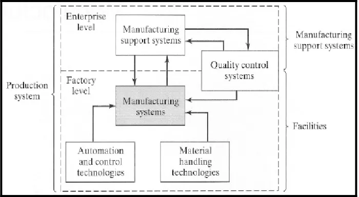
A manufacturing system is defined as a collection of integrated equipment and human resources, whose function is to perform one or more processing and/or assembly operations on a starting raw material, part, or set of parts. The integrated equipment includes production machines and tools, material handling and work positioning devices, and computer systems. Human resources are required either full time or periodically to keep the system running. The manufacturing system is where the value-added work is accomplished on the part or product. The position of the manufacturing system in the larger production system is seen in Figure 2.1 Examples of manufacturing systems includes (Groover, 2001):
a) One worker tending one machine, which operates on semi-automatic cycle
b) A cluster of semi-automatic machines, attended by one worker c) A fully automated assembly machine, periodically attended by a
human worker
d) A group of automated machines working on automatic cycles to produce a family of similar parts
Figure 2.1: The position of the manufacturing system in the larger production system.
2.1.1 Manufacturing System Components
Manufacturing system consists of several components. In a given system, these components usually include (Groover, 2001):
a) Production machines plus tools, fixtures, and other related hardware.
b) Material handling system.
c) Computer systems to coordinate and/or control the above components.